16 17
ENEN
SETTINGS (SETUP) SETTINGS (SETUP)
If Pre-Heating is switched on, the unit will heat the room up to the set cooling mode (day) temperature one hour before
daybreak (timer is on). At the beginning of the day, the room will be at the right temperature. Besides the advantage of
giving the day temperature a jump-start, this also prevents the cold parts of the unit from becoming wet, which reduces
or prevents mould build-up.
Note: Only works in conjunction with the timer and not in the light cell mode!
D:06 Slow cool-down (post-heating) on/off.
Slow cool-down (post-heating) can be switched on using this setting.
D:06 = 0 means Slow Cool-Down is off. This is the default setting.
D:06 = 1 means Slow Cool-Down is on.
If Slow Cool-Down is switched on, the unit will slowly cool the room until one hour after the end of the day.
Note: Only works in conjunction with the timer and not in the light cell mode!
D:07 Dual Room (cooling two rooms 12h by 12h) on/off.
Using this setting, you can switch on/off the cooling of two rooms alternately.
D:07 = 0 means Dual Room operation is off. This is the default setting.
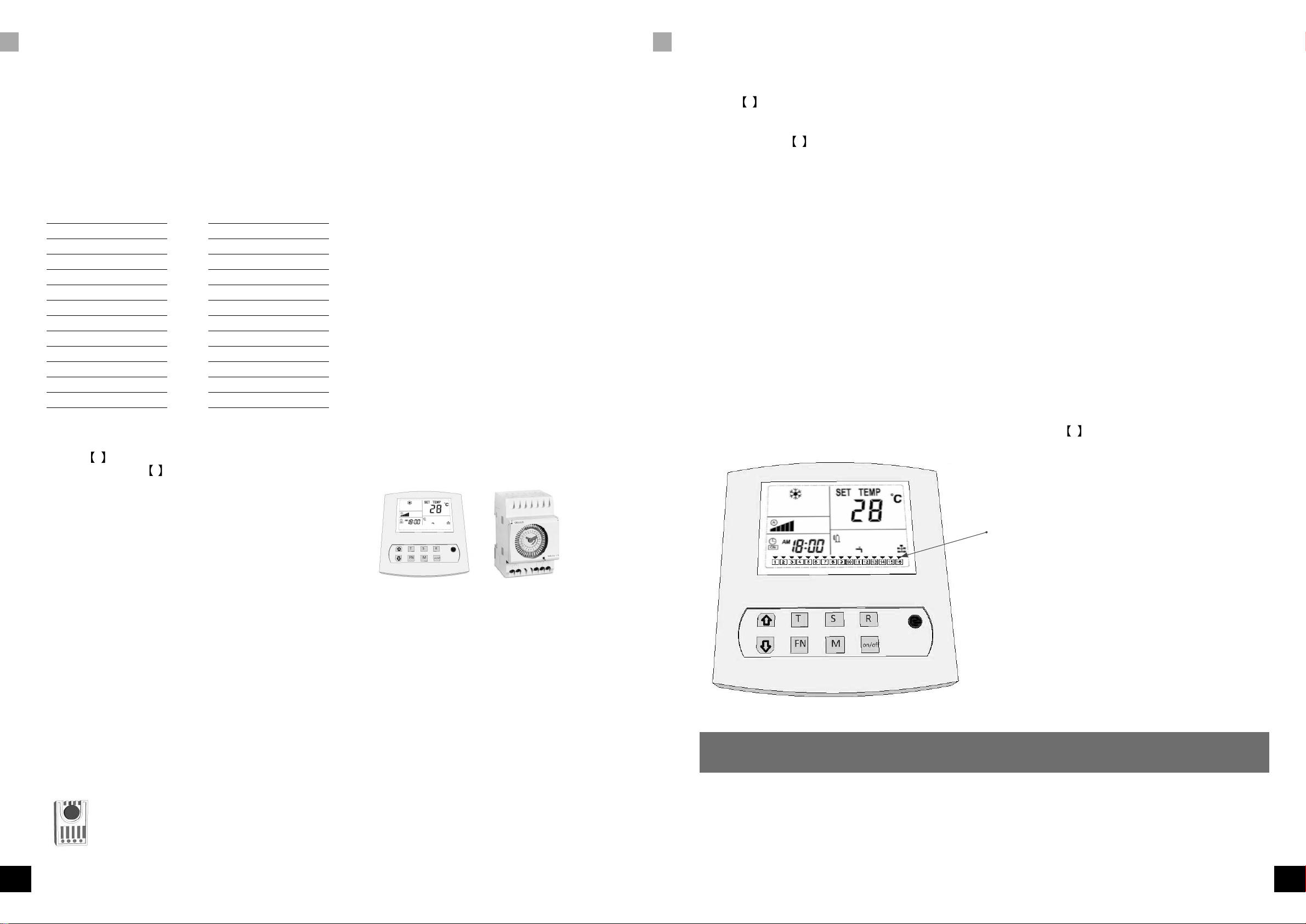
D:07 = 1 means Dual Room operation is on. If the Dual Room function is active,
the display will show the house icon at the bottom right-hand side.
To use this function, you will have to order a three-way valve and a connection set consisting of a three-way valve,
plenum box, second temperature sensor, external water seal and an extensive installation/user manual.
D:08 Alarm port N.O. (Normally Open) or N.C. (Normally Closed)
Using this setting, the alarm port can be adjusted.
D:08 = 0 means N.C. Normally closed. This is the default setting.
D:08 = 1 means N.O. Normally open.
Refer to the user manual for the correct settings of the SMS (GSM) detector or the alarm system that should be connected.
D:09 Water Valve options
You can opt to open the water valve only if there is a demand for water or only use the water valve if the water leakage
sensor detects a leak. Setting D:09 to 0 will only open the valve during cooling. Setting D:09 to 1 will only open the
valve when a leak occurs.
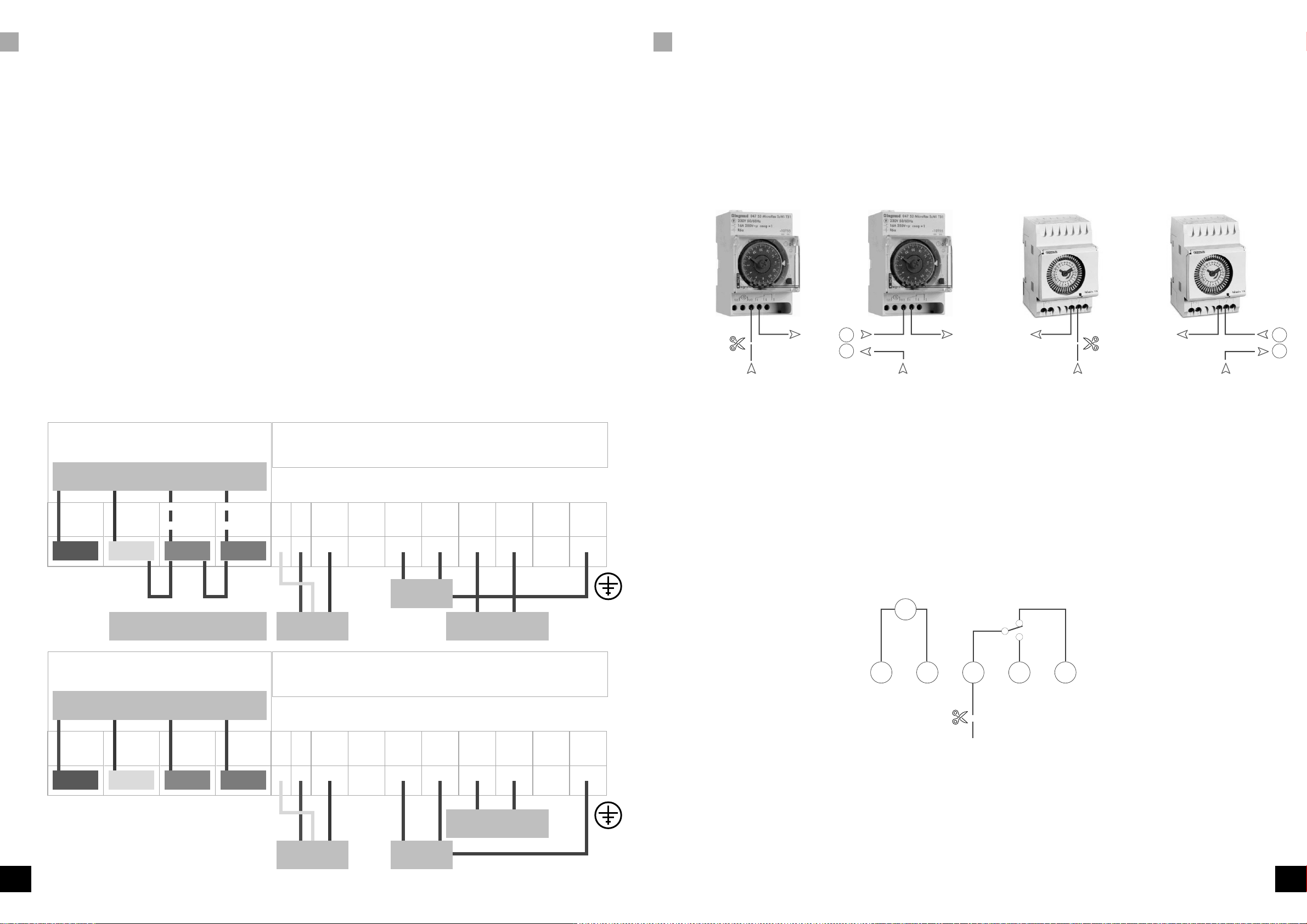
D:10 Timer port
If D:10 = 0, ports 15 and 16 will interrupt the High Temperature alarm. If D:10 = 1, the high temp alarm will not
occur through these contacts. If D:10 = 1, port 16 is common and ports 16 & 17 will be each other's alternate
contacts. The clock of the OptiClimate (OC) will operate these make-and-break contacts and the clock/timer of the OC
can replace the clock on the control panel. The lamps will operate synchronous with the cooling mode of the OC. To
install a High Temperature safeguard, contact 16 should be aligned with the alarm port on the printed circuit-board.
If there is a High Temperature alarm, this alarm will interrupt the timer’s signal and the temperature safeguard will still
operate. The setting of the alarm port should then be the standard setting (0 = N.C.).
D:11 Hysteresis of the temperature
Using this setting, you can adjust the hysteresis (bandwidth) of the temperature control. This is the temperature difference
required to switch the compressor on and off.
Setting:
D:11 = 2 means the hysteresis is 2. This is the default setting.
The hysteresis can be set from 1°C to 4°C in steps of 0.5°C. If, for example, the day temperature is set to 28°C and
the hysteresis to 2°C, the unit w cool at 29°C and stop idle time of the compressor should also be decreased. (D:27)
D:12 Minimum adjustable heating temperature
Using this setting, you can change the minimum adjustable heating temperature.
The settable values in D:12 are 16°C(standard), 20°C (maximum), 10°C(minimum).
D:13 Maximum adjustable heating temperature
Using this setting, you can change the maximum adjustable heating temperature.
The settable values in D:13 are 35°C (standard), 50°C (maximum), 25°C (minimum).
D:14 Minimum adjustable cooling temperature
Using this setting, you can change the minimum adjustable cooling temperature.
The settable values in D:14 are 16°C(standard), 20°C (maximum), 10°C (minimum).
D:15 Maximum adjustable cooling temperature
Using this setting, you can change the maximum adjustable cooling temperature.
The settable values in D:15 are 35°C(standard), 35°C (maximum), 25°C (minimum).
D:16 Anti-freeze protection of the cooling water
Using this setting, you can determine at which temperature the Anti-Freeze Alarm is activated.
The settings in D:16 are 3°C (standard), 10°C (maximum), 0°C (minimum).
D:17 Anti-freeze protection of the cooling block
Using this setting, you can determine at which temperature the Anti-Freeze alarm of the cooling block is activated. The
settings in D:17 are 0°C (standard), 5°C(maximum), -2°C (minimum).
D:18 Cooling water temperature too high
Using this setting, you can determine at which temperature the Cooling water temperature too high alarm is activated.
The settings in D:18 are 57°C (standard), 60°C (maximum), 40°C (minimum).
D:19 Cooling water temperature too low
Using this setting, you can determine at which temperature the Cooling water temperature too low alarm is activated.
The settings in D:19 are 4°C (standard), 10°C and 1°C(maximum), 0°C (minimum).
D:20 Not applicable
D:21 Cooling block too hot
Using this setting, you can determine at which temperature the Cooling block too hot alarm is activated. The settings
in D:21 are 24°C (standard), 30°C(maximum), 15°C (minimum). To activate the alarm, the temperature has to be too
high for a certain period of time. The time is determined by D:22. D:21 and D:22 jointly determine when Error 11
is activated.
D:22 Duration of cooling block too hot
Using this setting, you can determine how long it takes before a Cooling block too hot alarm is given. The settings in
D:22 are 30°C (standard), 40°C(maximum), 20°C (minimum).
The temperature level is determined by D:21. D:21 and D:22 jointly determine when E:11 is activated.
D:23 Temperature compensation of the room temperature sensor
Using this setting, you can calibrate the room temperature sensor. The setting can be changed if the indication on the
display does not correspond with reality. The settings in D:23 are 0°C (standard), 5°C (maximum), -5°C (minimum) set
in 0.5°C increments.
D:24 Temperature compensation of the cooling block temperature sensor
Using this setting, you can calibrate the cooling block temperature sensor. The settings in D:24 are 0°C (standard),
5°C(maximum), -5°C (minimum) set in 0.5°C increments.
D:25 Temperature compensation of the cooling water temperature sensor
Using this setting, you can calibrate the cooling water temperature sensor. The settings in D:25 are 0°C (standard),
5°C(maximum), -5°C (minimum) set in 0.5°C increments.