7
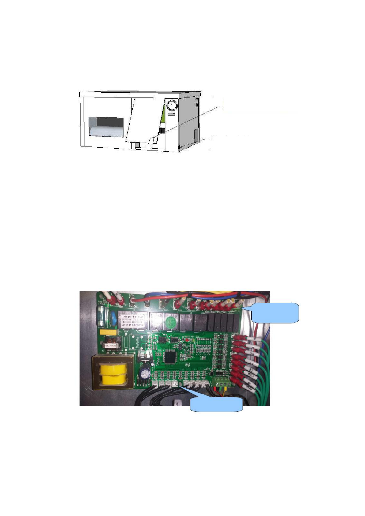
Room Temperature
The compartment is also the room temperature. This is already connected to the PCB. The sensor is
used by the opening in the panel through to the outside and is to be to be hung in line with the top
of the crop. The sensor must be protected against heat radiation but not placed in the shade, a
cover on top of the sensor is sufficient.
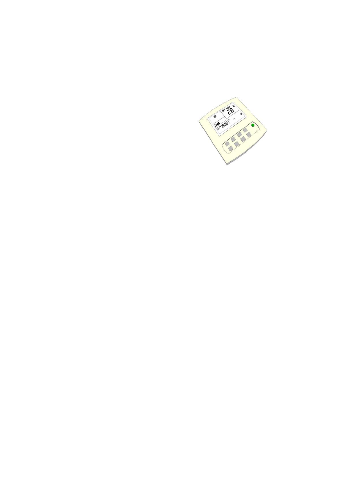
The Remote
The remote can also be hung in the
compartment is in space but also elsewhere.
OptiClimate can also operate outside the room.
The four core cable is already connected, and
entered by the opening in the panel, to be
carried out.
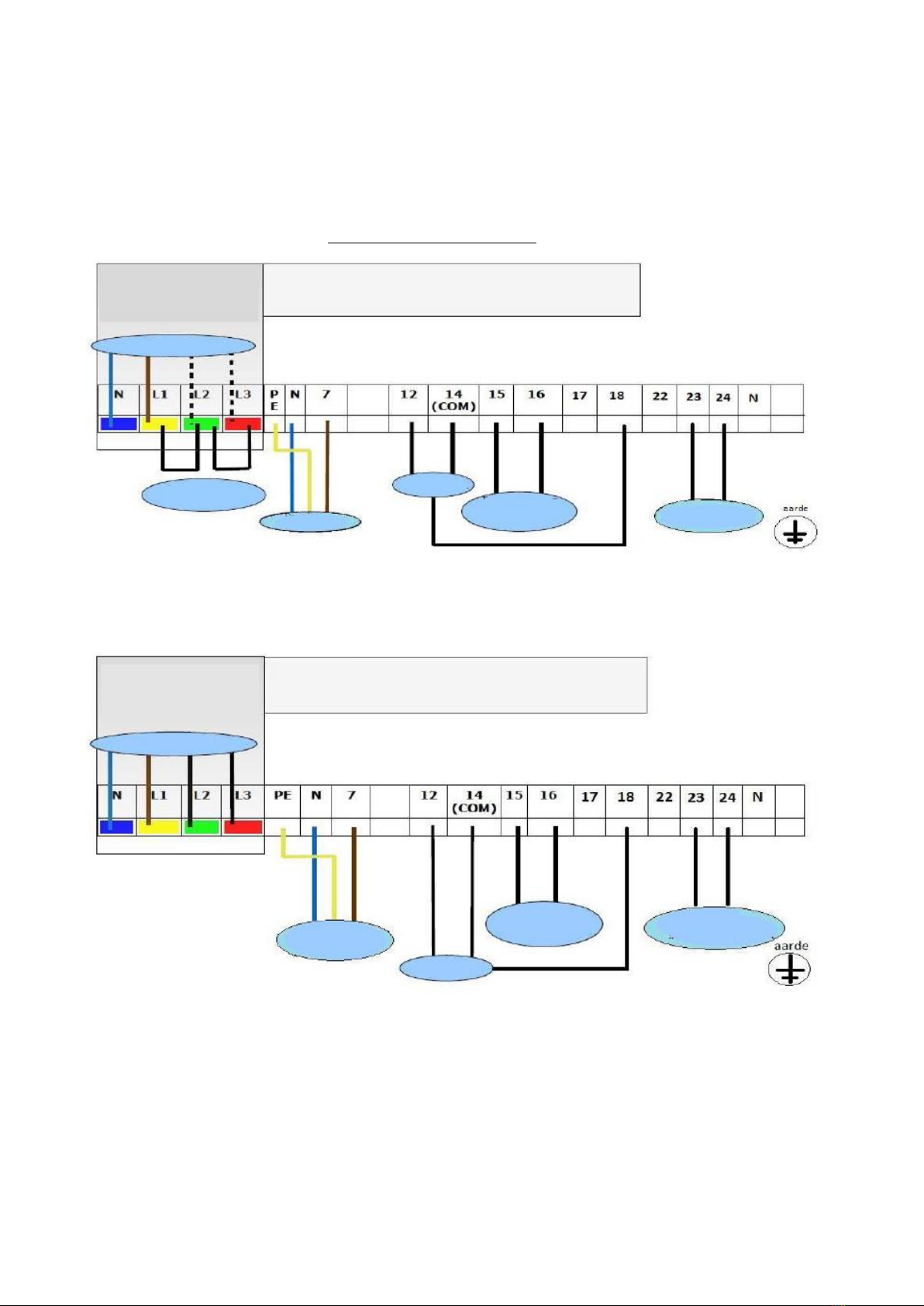
5-Core Cable
Included is a 5-pin connector to provide power to the outdoor unit and to connect the indoor unit.
The temperature in the outdoor unit is connected by the 5-core cable to the terminal strip in the
indoor unit and the white junction box to the outdoor unit. The 5-core cable must be passed through
the opening in the panel and is connected to the indoor unit as follows.
Blue (or black with # 1 *) N
Brown (or black with nr2 *) 7
Yellow / green PE
Black or gray (or black with # 3 *) 24
Black or gray (or black with # 4 *) 23
* (depending on the type of 5-core cable included)
Power cables
There are five different OptiClimate models. For your safety and the safety of the OptiClimate serve
to connect the power supply, the following specifications are to be observed; Use the specified
circuit breakers and cable sizes
Model Circuit breaker Cable sections
3500pro3 first phase D16 automatic 2.5 mm2 cable
3500pro3 3 phase automatic D10 2.5 mm2 cable
6000pro3 first phase D25 automatic 4.0 mm2 cable
6000pro3 3 phase automatic D16 2.5 mm2 cable
10000pro3 first phase D35 automatic 4.0 mm2 cable
10000pro3 3 phase automatic D20 2.5 mm2 cable
15000pro3 (S) 1 phase D50 automatic 6.0 mm2 cable
15000pro3 (S) 3 phase automatic D35 4.0 mm2 cable
15000pro3 3 phase automatic D25 4.0 mm2 cable *
* This unit is the compressor divided over 3 phases