OPTICLIMATE PRO3 Series User manual

NL
PLEASE READ THE FOLLOWING INFORMATION
CAREFULLY BEFORE USING THE UNIT:
High Temperature Safeguard on page 7
Delete alarm history on page 12
Dehumidify without cooling pro4 on page 12
OPTIMAL CLIMATE CONTROL
OPTICLIMATE
OPTICLIMATE.NL
OptiClimate is a registered trademark of
airSupplies
PRO3 AND PRO4 (INVERTER) SERIES
Installation and User Guide

2 3
ENEN
blank
blank
INSTALLATION INSTALLATION
Installation
Fan installation (front / side)
If the unit is placed in a narrow room or in the ridge of a gable roof, the fan outlet side can be installed at the short side
of the unit. This can be done simply by reversing the dark panels so that the fan panel is moved around to the short side
of the unit. Loosening the corner bracket will eliminate the need for disconnecting cable connections.
Installation
To guarantee proper air suction, leave at least 15cm of space between the wall and the backside of the unit, where the
carbon & dust lters and air inlet are located. At least 15cm of space should also be left between the topside of the unit
and the ceiling. Larger spaces are preferred. The unit must stand free from the wall to avoid contact noises.
The unit should be mounted in such a way that the side of the condensation drain is at least 1 cm lower than the other
side (slope) to ensure that the condensate drains properly. In practice, the 1 cm elevations at all corners – except the
corner of the condensate drains – are exactly right for a correct fall. Using a spirit level is recommended.
To avoid contact noises, the OptiClimate comes standard with rubber shock absorbers that are suitable for suspended
installation. If the OptiClimate is going to be placed on a solid base, the rubber shock absorbers supplied with the
connection set need to be used.
Special insulating springs can also be supplied for areas that have to be extra quiet. Placing the insulating springs on
the supports will ensure that the unit has automatic fall to the condensation drain.
Installation of rubbers Installation of insulating springs
The rubber feet with which the OptiClimate is placed on the pallet are use to suspend the unit by means of thread ends.
A thread end, a large washer and a nut must be tted. (not supplied)
NL
1 cm fall

4 5
ENEN
blank
blank
ELECTRICAL CONNECTION ELECTRICAL CONNECTION
Electrical connections
Automatic moisture meter,
Remote Control, Solenoid
Valve, Temperature Safeguard,
temperature sensors in the area
Power cord
First, the panel at the left side near the manometer should be removed to make the various electrical
connections. A magnetic valve, water leakage sensor, automatic moisture meter, remote control and room
temperature sensor are supplied with the unit. Their cables can be led to the outside through the opening at the bottom
of the panel. The power cable for the power supply can be led through the black feed-through rubber at the side of the
unit.
Electric solenoid valve
The plug of the solenoid valve should be connected using the black cable supplied with the unit, as shown in the
illustration below.
The other end of the cable should then be connected to the appropriate terminals - terminal N and terminal 7 - on the
terminal strip (see page 6). The third connection of the solenoid valve can be used as earthing.
Water leakage sensor
The connection set contains a loose, 5m long white wire: the water leakage sensor. This sensor is connected to the
eighth terminal on the printed circuit-board. The sensor cable should be led to the outside through the opening in the
panel and should be placed on the ground at the lowest point. The end of the sensor cable can be split into several
cores using a connector, so that more than one point is secured against leakage.
If the sensor has a black cap, this should be cut back and stripped 5mm and the cores should be stripped. Connect the
other side to the little white plug on the printed circuit-board as shown in the illustration. In case of water leakage, the
water supply will be stopped immediately by means of the electrical valve in the water pipe.
Room
Temperature sensor
AI01
Water Leak-
age
sensor AI08
Alarm port
Alarm port
The printed circuit-board has an alarm port, which is activated (makes contact) by a malfunction (error). This contact
can be connected to a GSM detector. The contact can be set to NO (contact open) or NC (contact closed) using the
Settings menu This means that the contact will be opened or closed in case of detection. See the manual of the GSM
detector or alarm for this.
Automatic moisture meter with light cell
The automatic moisture meter with built-in light cell supplied with the unit is already connected. The cable should be led
through the opening in the panel. The automatic moisture meter should be hung in the room and may NOT be covered.
The light cell in the automatic moisture meter automatically switches the OptiClimate from day to night mode.
Room temperature sensor
The compartment also has a room temperature sensor, which is already connected to the printed circuit-board. This
sensor should be led to the outside through the opening in the panel and should be hung at the level of the upper side
of the vegetation. The sensor should be protected against heat radiation but may not be put in the shade. A
protective cover over the sensor is sufcient.
The remote control
The remote control contained in the compartment
can be hung in the room but can also be hung
elsewhere. This way the OptiClimate can also be
controlled from outside the room. The four-core
cable is already connected and should be led to
the outside through the opening in the panel.

6 7
ENEN
blank
blank
ELECTRICAL CONNECTION ELECTRICAL CONNECTION
Power cables and circuit breakers
Six different OptiClimate models are available. For your safety and the safety of the OptiClimate, the following
specications should be observed when connecting the power supply: use the circuit breakers (MCB) and cable
thickness specied.
Model
2000 PRO3 & PRO4 1 phase D16 MCB 2.5mm2 cable
2000 PRO3 & PRO4 3 phase D16 MCB 2.5mm2 cable
3500 PRO3 & PRO4 1 phase D16 MCB 2.5mm2 cable
3500 PRO3 & PRO4 3 phase D10 MCB 2.5mm2 cable
6000 PRO3 & PRO4 1 phase D25 MCB 4.0mm2 cable
6000 PRO3 & PRO4 3 phase D16 MCB 2.5mm2 cable
10000 PRO3 & PRO4 1 phase D35 MCB 4.0mm2 cable
10000 PRO3 & PRO4 3 phase D20 MCB 2.5mm2 cable
15000 PRO3 & PRO4 Inverter 1 phase D50 MCB 6.0mm2 cable
15000 PRO3 & PRO4 Inverter 3 phase D35 MCB 4.0mm2 cable
15000 PRO3 & PRO4 3 phase D25 MCB 4.0mm2 cable *
* The compressor of this unit is divided over 3 phases
The cables for the supply voltage should be led through the feed-through rubber at the side and connected to the left-
hand side of the terminal strip as described in the illustration. The earthing can be connected to the PE terminal or to
the screw on the metal housing at the bottom right of the terminal strip.
Inverter models
Connecting to the terminal strips left corner Connecting to the terminal strips right corner
D
blue
N
blue
7 15
L1
yellow
16
L2
green
12
L3
red
14
(COM)
18
P
EN
INVERTER 1 PHASE 230VOLT
The automatic
moisture meter
Temperature safeguard
Solenoid valve
Earthing
23
(A+B series)
29
(C+> series)
24
(A+B series)
30
(C+> series)
Temperature sensor
outdoor unit
When connecting the inverter models to 1 phase 230volt, there need to be bridges between L1, L2 and L3. There should
also be a bridge between N and D. With a new unit, the bridges are connected.
Earthing
23
(A+B series)
29
(C+> series)
24
(A+B series)
30
(C+> series)
Temperature sensor
outdoor unit
Connecting to the terminal strips left corner Connecting to the terminal strips right corner
D
blue
N
blue
7 15
L1
yellow
16
L2
green
12
L3
red
14
(COM)
18
P
EN
INVERTER 3 PHASE 400VOLT
The automatic
moisture meter
Temperature safeguard
Solenoid valve
When connecting the inverter models to 3 phase 400volt, there may not be any bridges between L1, L2 and L3. There
may also not be a bridge between N and D. With a new unit, the bridges are always connected.
Note: Failure to observe the above description can cause irreparable damage to compressor/ inverter.
2 loops with 230V 1 phase
No loops with 400V 3 phase
Connecting to the terminal strips left corner Connecting to the terminal strips right corner
N
blue
7 15L1
yellow
16L2
green
12L3
red
14
(COM) 18
P
EN
230V 3 Phase
The automatic
moisture meter Earthing
2 loops with 230V 1 phase Solenoid valve Temperature safeguard
Connecting to the terminal strips left corner Connecting to the terminal strips right corner
N
blue
7 15L1
yellow
16L2
green
12L3
red
14
(COM)
18
P
EN
400V 3 Phase
The automatic
moisture meter
Earthing
Solenoid valve
Temperature safeguard
No loops with 400V 3 phase

8 9
ENEN
blank
blank
WATER-SIDED CONNECTIONS WATER-SIDED CONNECTIONS
High temperature safeguard
Using this safeguard, the OptiClimate can switch off the heat sources (e.g. lamps) when the temperature in a room
becomes too high. The unit has a terminal that can be connected to the timer of a control panel, for example.
The feed wire running to the switch in the timer should be interrupted for this purpose. Terminal 1, for example, is for a
Grasslin clock and terminal 4 for a LeGrand timer.
16
15
16
15
LeGrand Grasslin
The two ends should be connected to terminals 15 & 16 on the terminal strip in the electrical compartment of the
OptiClimate. The OptiClimate supplies the power for the timer.
The OptiClimate supplies the power for the timer. If the room temperature exceeds 35°C, the OptiClimate will interrupt
the circuit, switching off the heat sources. ERROR 15 is then displayed on the remote control.
Always refer to the timer manufacturer's manual if a model other than the one shown is used.
M
L N
Supply and drain connections of the cooling water
The unit has a water inlet and outlet. The inlet should be installed at a draw-off point with a solenoid valve installed
between the draw-off point and the inlet (always check the ow direction arrow on the valve!). The solenoid valve
should be installed as close as possible to the draw-off point, as this is the water seal. When a leak occurs, the
solenoid valve closes automatically.
Make sure that the black magnetic coil of the solenoid valve is directed upwards (preferred) or to the side. If it is directed
downwards, condensate from the valve might enter the coil. Make sure that the solenoid valve is installed at a xed
point that is always easily accessible to the user.
Water drainage
Condensate drainage
Solenoid valve
16mm PE pipe
Pipe insulation
Solenoid valve in the supply pipe of the water
A lter should be placed in the water inlet. This lter prevents blockage in the unit. Disassembly of the lter often releases
dirt into the unit. As such, it may only be removed after contacting the Technical Service department.
It is recommended to insulate the water supply line in order to prevent condensation build-up. The upper water connection
is the water outlet. The water outlet can be connected directly to the drain (sewer). Alternatively, the warm water can
be used for heating purposes.
Note : Only use solid copper or LDPE pipes and afx these properly to the wall using clamps. Always avoid putting the
LDPE under tension. Make sure that the solenoid valve is afxed properly to the wall or another xed point. Never use a
garden hose!
When all the LDPE connections are checked for leaks and the unit operates properly, all are ttings should be glued. You do
this by unscrewing the coupling, applying some glue to the thread and re-tightening the blue are nut. If done properly, the
are ttings will never come loose as a result of vibration. If it is necessary to loosen the are ttings, then two water pump
pliers will do the trick.
Copper pipes of 15 mm or LDPE pipes of 16 mm are sufcient for all units. If several units have to cool at more than
15 kW, the main pipe should be 20 mm copper or 20 or 25 mm LDPE. If the supply pipe has high pressure, a copper
pipe of 15 mm will cool up to 30 kW.

10 11
ENEN
blank
blank
WATER-SIDED CONNECTIONS PUTTING INTO OPERATION
All types of cooling water (tap, well, pond or swimming pool water) can be used for cooling. However, tap water is
preferred because you won't need to rely on additional electric pumps. Well water contains clay and iron particles that
accumulate on the inner wall of the heat exchanger. The result is that sooner or later the unit will cool less effectively or
not at all. If you use well water, you can install a lter, but such a solution requires maintenance. A normal 22mm tap
water connection has sufcient capacity to continuously cool three or four These are 3 or 4 OptiClimate 15000 units.
We also have suitable solutions for larger installations when there are problems with the water supply and discharge.
In such cases, please contact the Technical Service department.
Discharge of the condensation water
The unit will also dehumidify the air during cooling. The moisture extracted from the air comes into the condensation
drain. The condensation drain is connected to a sturdy garden hose or a pipeline that does not bend easily. The
condensation water drips from the hose, which can be connected to the drain pipe. The condensate can also be used
as feed water. The cooling block has been adjusted to prevent metals or oxides from entering the condensate. This is
ideal when the only feed water available is hard water.
The drain pipe of the condensation water may not have loops and may not be put under the water level in a drum.
If the unit is installed at the same level or lower than the drain or sewer, a condensation lift pump can collect the water.
This small lift pump pumps the water through a hose of 9mm to a height of 4 metres into the drain. Stronger pumps are
also available.
Drain pump of the condensation water incorrect drain installation
The drain to the pump must not be under the water level and the pipe may not have loops as shown above. It's possible
that too much air is sucked in through the condensation water pipe causing the condensate water not to drain properly.
Then there is too much resistance in the intake system. Dimension hoses of e.g. a plenum box as large as possible
and ensure that during operation all panels are mounted on the unit. A special syphon can also be mounted. Ask your
dealer.
The unit is now installed and ready to use
Remote Control
Operation = Temp up / scroll
= Temp down / scroll
T= Press and release to set the time
/ press and hold to set the timer
FN = Fan speed
S = Press and release to read Sensors / press and hold to bring
up the Menu
R = Press and release to conrm / press and hold to delete
error codes
M = Press and release to switch between day and night mode.
Press and hold to turn automatic light cell mode on/off.
On/Off = Turn unit on/off or conrm menu option.
1) On/Off key
The unit is switched On or Off using the On/Off key. The LED will be green when the unit is On. The LED will be red
when the unit is Off. In case of malfunctioning, the LED will ash red and green. The On/Off key is also used to conrm
a menu selection.
2) Mode key M
Pressing the mode key will switch the mode from day mode (cooling) to night mode (heating/dehumidifying). The
display will show a lit snowake in day mode and a sun with drops of water in night mode.
Temperatures for the day and night can be set using the mode function.
These can be changed later, if required.
3) Fan speed key Fn
This key is used for selecting the air speed of the fan. The sequence is as follows:
A
Automatic Low Medium High
The speed changes whenever the Fn key is pressed. If you select the automatic fan mode in the Cool mode, the unit will
ventilate more or less depending on the need for cooling.
By selecting day or night with the mode key a different fan speed can be chosen for both day and night. For the night
we recommend the lowest fan speed for heating and dehumidifying. If a great deal must be dehumidied during the
night, the fan speed can be set to position 2 or 3.

12 13
ENEN
blank
blank
PUTTING INTO OPERATION PUTTING INTO OPERATION
Inverter
The OptiClimate inverter models adjust the cooling capacity to the need. Non-Inverter models operate on
an on / off basis, while the inverter models run the compressor harder/ softer when more or respectively
less cooling capacity is required. This provides an even more stable climate and prevents the frequent tripping
of the unit in case of over capacity.
The inverter function operates on the basis of the fan speed. This means that the fan can be set to automatic
in the day position, using the remote control (FN). If the fans are set at a xed rate, the inverter
function is switched off and the compressor also runs at a xed rate. (resp. low / middle / high). For the night position,
we recommend that you always use the low setting.
4) Temperature setting
Users can set the temperature from 16°C to 34°C.Pressing the
or
key will show the set temperature SET TEMP on the
display. By pressing it once more, you can set the required temperature. The set temperature will be saved and stored
after 3 seconds. Switching between day and night temperatures is done using the Mmode key.
5) Time Setting Tkey
Press the Tkey once to select the hours and then press the
or
key to change the hours. Press the Tkey again,
and the minutes will ash and then press the
or
key to change the minutes. Now press the R key to conrm the
hours and minutes that you entered.
6) Automatic Light Cell setting (Day /Night programme)
The automatic moisture meter in the pro3 series has a light cell, which switches to the day mode when it sees the light
is on and to the night mode when the light is off. Only the Day/Night temperatures have to be set, the rest is done
automatically.
If you want to set the unit manually, the automatic light cell can be switched off and the unit will operate manually.
By pressing the M key for 3 seconds, the mode switches from light cell to manual. By pressing the Mkey again for
3 seconds, the mode switches from manual to light cell. If the automatic light cell
is activated, the display shows an A.
Note: It is important to note that when the Timer setting is programmed the automatic light cell mode is
deactivated. Therefore, program a Timer only if you want to use advanced options. The Timer mode is active
when a clock iconappears in the display.
The external automatic moisture meter for the light cell should be connected to the terminal strip in the electrical
compartment (terminals 12, 14 and 18). Otherwise the unit will remain in the night mode because light is not detected.
This is connected by default.
7) Timer Setting (DAY/NIGHT programme)
As a general rule, we recommend using the automatic light cell mode. Only set the timer if you do
not want to work with the light cell!
This function can be used to set the DAY/NIGHT programme. The programme restarts every day regardless of which
day it is. If the timer is set, the display will show the clock icon next to the time:
Press the Tkey for 2 seconds. When "---", ON becomes visible, you can change the timer setting. Pressing the
or
key will allow you to set the hours of the ON time. Pressing the Tkey again will allow you to set the minutes of the ON
time. The ON time is the time that the unit will start to cool.
Pressing the Tkey again will allow you to set the OFF time. The OFF time is the time that the unit will start to heat/
dehumidify. If the timer is not set yet, the display will show "--:--" or the time that was already set.
Example:
The unit must cool between 8:00 AM and 8:00 PM.
The ON time should then be set to 8:00 AM
and the OFF time to 8:00 PM
AM = after midnight (from 0:00 to 12:00 hours)
PM = after noon (from 12:00 to 24:00 hours)
1:00 AM equals 01:00
2:00 AM equals 02:00
03:00 equals 03:00
04:00 equals 04:00
05:00 equals 05:00
06:00 equals 06:00
07:00 equals 07:00
08:00 equals 08:00
09:00 equals 09:00
10:00 equals 10:00
11:00 equals 11:00
12:00 PM equals 12:00
1:00 PM equals 13:00
2:00 PM equals 14:00
3:00 PM equals 15:00
4:00 PM equals 16:00
5:00 PM equals 17:00
6:00 PM equals 18:00
7:00 PM equals 19:00
8:00 PM equals 20:00
9:00 PM equals 21:00
10:00 PM equals 22:00
11:00 PM equals 23:00
12:00 AM equals 00:00
Deleting the time when setting the timer (switching off the timer)
Press the Rkey, and the time is deleted. The display will show "--:--". CLOSING: Press the Tkey three times to close
immediately or wait 10 seconds to close automatically.
The settings of the current time and the timer settings
should run synchronously with the times of the control panel.
All clocks must run synchronously when the timer function
is used.
8) Using the automatic moisture meter for dehumidifying during the night
The automatic moisture meter can be set to the required maximum air humidity during the night. If the Night mode is
active and the automatic moisture meter indicates that the unit should dehumidify, the Drop icon starts to ash. During
dehumidication, the electrical heating elements will switch on and water will be consumed in the pro3. This will not
happen with the pro4.
Dehumidication during the day (only pro4)
Both the pro3 and the pro4 will always dehumidify as long as there's a demand for cooling.
If continuous drying without uctuations is desired, or an as low as possible relative humidity, the Pro4 can also
dehumidify without the need for cooling. This function can be activated by setting option D:32 to 1 in the menu. With
daytime dehumidication, no water will be consumed.
If, for example, a constant air humidity and temperature are required continuously in a climatic chamber, cool at night
must be activated in the menu option D:04. By pressing and holding the M key the light cell is deactivated and by
pressing and releasing the M key a choice must be made for the night setting. (icon: sun with drops) The unit can now
cool, heat and humidify.
The automatic moisture meter

14 15
ENEN
blank
blank
PUTTING INTO OPERATION SETTINGS (SETUP)
9) Reading function for the temperature sensors
Press the Skey and the sensor will show the temperatures. The number and temperature of the sensors will show in the
spot of the clock. Pressing the
and
keys will allow users to select the reading of the various sensors.
CLOSING: Press the Skey to close immediately or wait 60 seconds to close automatically.
C:01= C:01 = Temperature cooling block
C:02= Temperature drain water
C:03= Temperature supplied water (with dual room conguration, this will be the temperature sensor for room 2)
C:04= Intake air temperature
C:05= Temperature outlet air
C:06= Temperature of low-pressure refrigerant for compressor
C:07= Water leakage sensor
10) Reading function for the error codes
The unit malfunctions if the ON/OFF LED ashes red and green. E:XX will show the actual error code. If the problem is
solved automatically, the error code will disappear.
The error log (alarm history) in located at the bottom in the display of the remote control. If an error occurs, the error
will be continuously visible at the bottom of the display, even if the error has been solved. This way a malfunction or
incorrect setting that is about to come up can be noticed and/or resolved at an early stage.
Deleting the error log (alarm history)
When resolved, errors in the log can be deleted by pressing and holding the Rkey.
Error codes
Note : Keep the alarm history clear so that problems can be easily / resolved at an early stage!
11) Water Leakage safeguard
Ifthereiswaterontheground-dueforexampletoanincorrectlymountedcouplingorablockedsewer-andthewatermakescontact
with the water leakage sensor (the at white wire with two blank cores at the end), the unit will stop cooling and the solenoid valve will
close immediately. The unit will only start operating normally after the leak is repaired and the fault is reset by pressing
the On/Off key.
12) Alarm port
The printed circuit-board has an alarm port, which makes contact when an alarm or error occurs. This contact can be
connected to an alarm system or SMS (GSM) detector.
13) Compressor Active mode
If the compressor operates, the display will show the Compressor icon at the bottom right-hand side,
it will disappear when the compressor is turned off. The compressor only operates during the DAY
period, if the set temperature is exceeded, and during the NIGHT period, if the set air humidity is
exceeded.
14) Heating Elements Active mode
If the heating elements are turned on, the display will show the Hot Air icon at the bottom right-hand side,
it will disappear when the heating elements are turned off. The heating elements only operate during the
NIGHT period, if the temperature reaches a value below the set value.
Setting the cooling capacity
Capacity control
The capacity is factory set at 1.6 MPa
1.5-1.7MPa is an average setting. Your specic application might require higher or lower cooling capacity. The
maximum cooling capacity is at 1.3MPa and the minimum cooling capacity is at 2.0MPa. The unit will consume more
water at a higher cooling capacity than at a lower cooling capacity.
To adjust the cooling capacity, turn the set screw of the capacity control. This set screw is located at the side of the unit
under the Cooling Capacity Control sticker. By turning the set screw to the left, the pressure will increase and the cooling
capacity will decrease, and by turning the set screw to the right, the pressure will decrease and the cooling capacity
will rise. It is recommended to do this if there are heat sources in the room, so that the unit will not turn off constantly
because the temperature in the room drops below 16°C. (The pressure on the manometer is not the water pressure, but
the pressure of the refrigerant)

16 17
ENEN
blank
blank
SETTINGS (SETUP) SETTINGS (SETUP)
This menu allows you to change certain settings and to set the heating, temperature safeguard, auto restart and
hysteresis. Pressing the Skey for more than 6 seconds will open the Settings menu. The display will show a capital
D: followed by a number from 01 to 32. Briey pressing the S key allows you to scroll through the settings. The rst
setting is D:01, the second setting is D:02, etc.
Use the
or
key to change a setting. You press the ON/OFF key to conrm. If you do not want to change anything
and exit the menu, press the Rkey. The settings range from D:01 to D:32. Do not adjust settings D:16 to D:22. These
are factory settings.
To restore the factory settings, press and hold the M key until the Settings menu opens. All settings will now be restored
to factory settings. Conrm this with the on/off key.
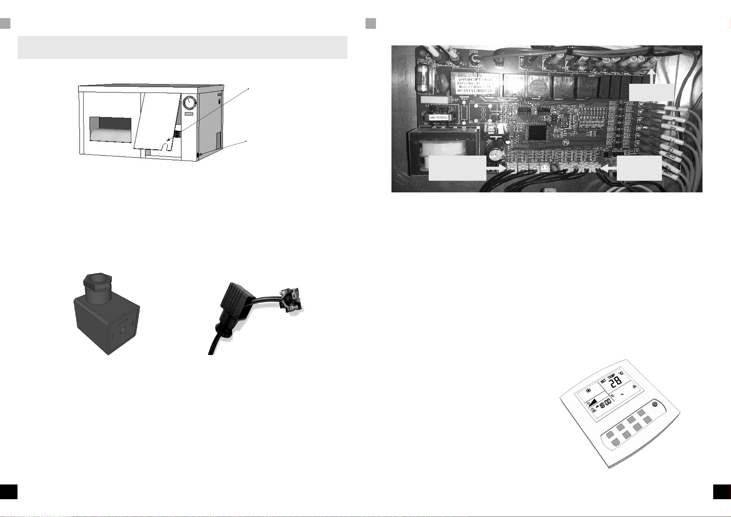
D:01 Switching the heating elements on/off
Depending on the model, an OptiClimate has 2 or 3 heating elements. The heating elements of 1-phase systems are
connected to 1 phase and the heating elements of 3-phase systems are divided over all phases.
Each of these elements can be switched on and off individually in the Settings menu. If a central heating system is used
for heating, for example, all of these heating elements can also be switched off at the same time.
Setting:
D:1 = 3 means all three elements will heat
D:1 = 2 means two elements will heat
D:1 = 1 means one element will heat
D:1 = 0 means all elements are off
D:02 Temperature safeguard
If the room temperature exceeds 35°C, terminals 15 and 16 on the terminal strip of the unit will switch off the
heating elements in the rooms that have to be cooled. The switch-off temperature can be changed using the D:02
setting. The minimum temperature for switching off is 30°C and the maximum temperature is 40°C. If the temperature
drops below the set temperature for cooling mode again, the safeguard will switch off and restart the heat sources.
The safeguard does not affect the operation of the OptiClimate. However, the display will show the error message
E:15. (also see the fault code list)
D:03 Auto Restart after power interruption
If the power is interrupted when the unit is on and the power is restored, the unit will switch on by default. If you want
the unit to remain off after a power interruption caused by an external fault, you should change the D:03 setting.
Setting:
D:03 = 0 means Auto Restart is off.
D:03 = 1 means Auto Restart is on. This is the default setting. The display will show error code 14 in case of power
interruption. See also the fault code list.
D:04 Night cooling (Cool at Night) on/off.
Using this setting, the night cooling can be switched on.
D:04 = 0 means Cool at Night is off. This is the default setting.
D:04 = 1 means Cool at Night is on.
If in the timer off mode the minimum temperature is, for example, set to 22°C, the unit will cool the room to 22°C in the
night mode. If the room temperature drops below 22°C, the unit will begin to heat the room. This function is useful in
warm climates, in a very well-insulated room or with other sources of heat that cannot be switched off.
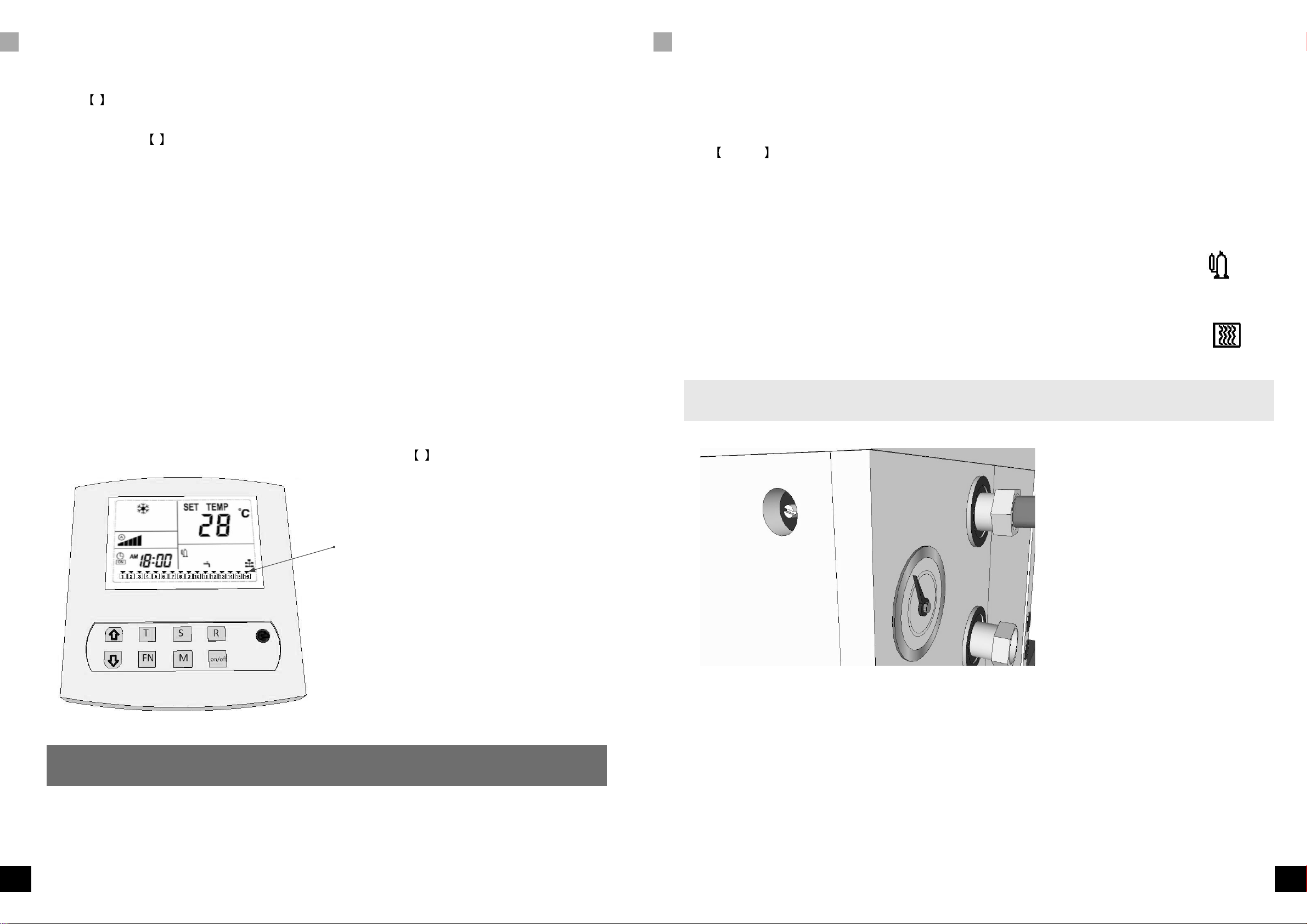
When the Cool at Night function is active a moon icon will be shown on the display.
D:05 Pre-Heating on/off.
Pre-heating can be switched on using this setting.
D:05 = 0 means Pre-Heating is off. This is the default setting.
D:05 = 1 means Pre-Heating is on.
If Pre-Heating is switched on, the unit will heat the room up to the set cooling mode (day) temperature one hour before
daybreak (timer is on). At the beginning of the day, the room will be at the right temperature. Besides the advantage of
giving the day temperature a jump-start, this also prevents the cold parts of the unit from becoming wet, which reduces
or prevents mould build-up.
Note: Only works in conjunction with the timer and not in the light cell mode!
D:06 Slow cool-down (post-heating) on/off.
Slow cool-down (post-heating) can be switched on using this setting.
D:06 = 0 means Slow Cool-Down is off. This is the default setting.
D:06 = 1 means Slow Cool-Down is on.
If Slow Cool-Down is switched on, the unit will slowly cool the room until one hour after the end of the day.
Note: Only works in conjunction with the timer and not in the light cell mode!
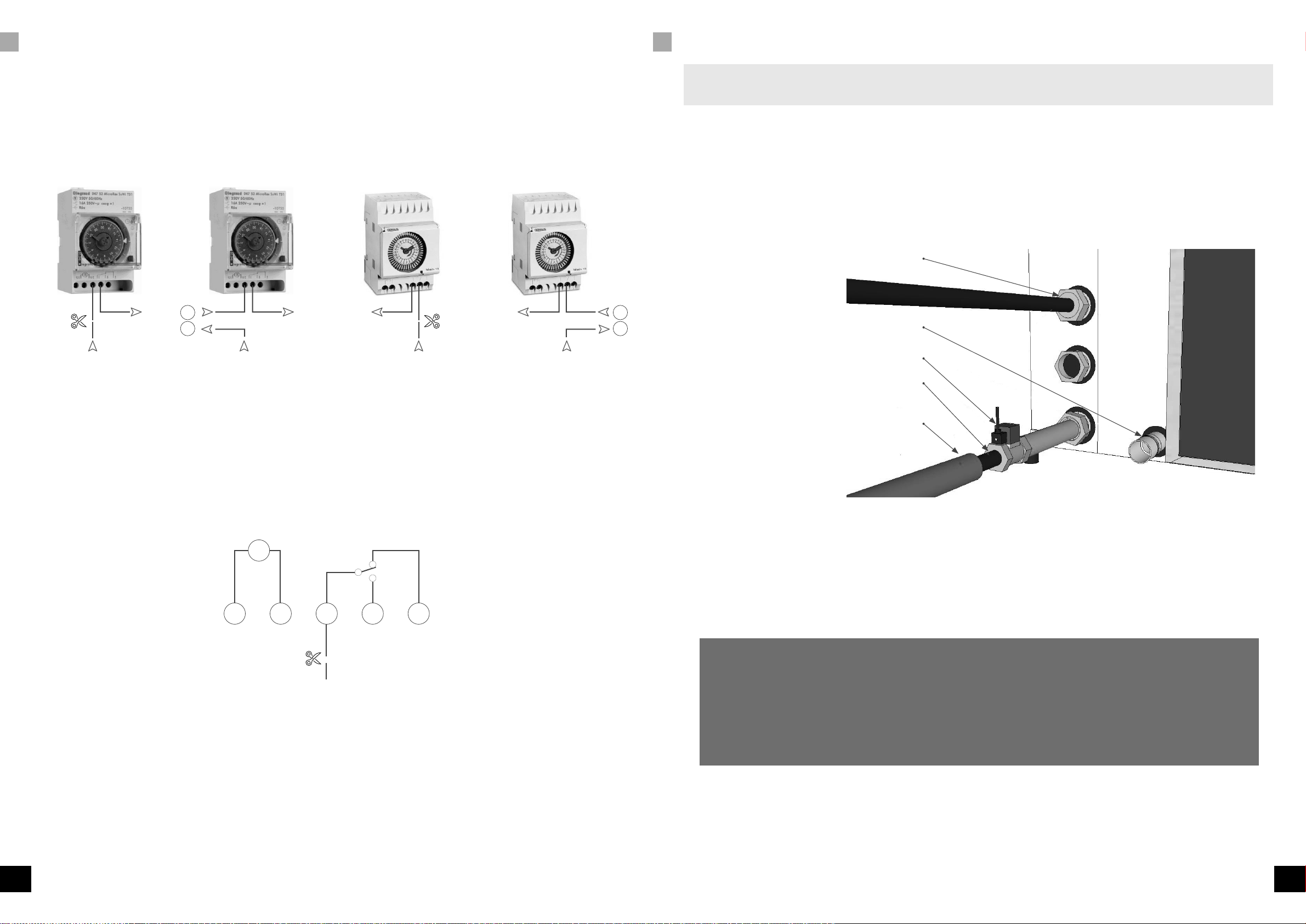
D:07 Dual Room (cooling two rooms 12h by 12h) on/off.
Using this setting, you can switch on/off the cooling of two rooms alternately.
D:07 = 0 means Dual Room operation is off. This is the default setting.
D:07 = 1 means Dual Room operation is on. If the Dual Room function is active, the display will show the house icon
at the bottom right-hand side.
To use this function, you will have to order a three-way valve and a connection set consisting of a three-way valve,
plenum box, second temperature sensor, external water seal and an extensive installation/user manual.
D:08 Alarm port N.O. (Normally Open) or N.C. (Normally Closed)
Using this setting, the alarm port can be adjusted.
D:08 = 0 means N.C. Normally closed. This is the default setting.
D:08 = 1 means N.O. Normally open.
Refer to the user manual for the correct settings of the SMS (GSM) detector or the alarm system that should be connected.
D:09 Water Valve options
You can opt to open the water valve only if there is a demand for water or only use the water valve if the water leakage
sensor detects a leak. Setting D:09 to 0 will only open the valve during cooling. Setting D:09 to 1 will only open the
valve when a leak occurs.
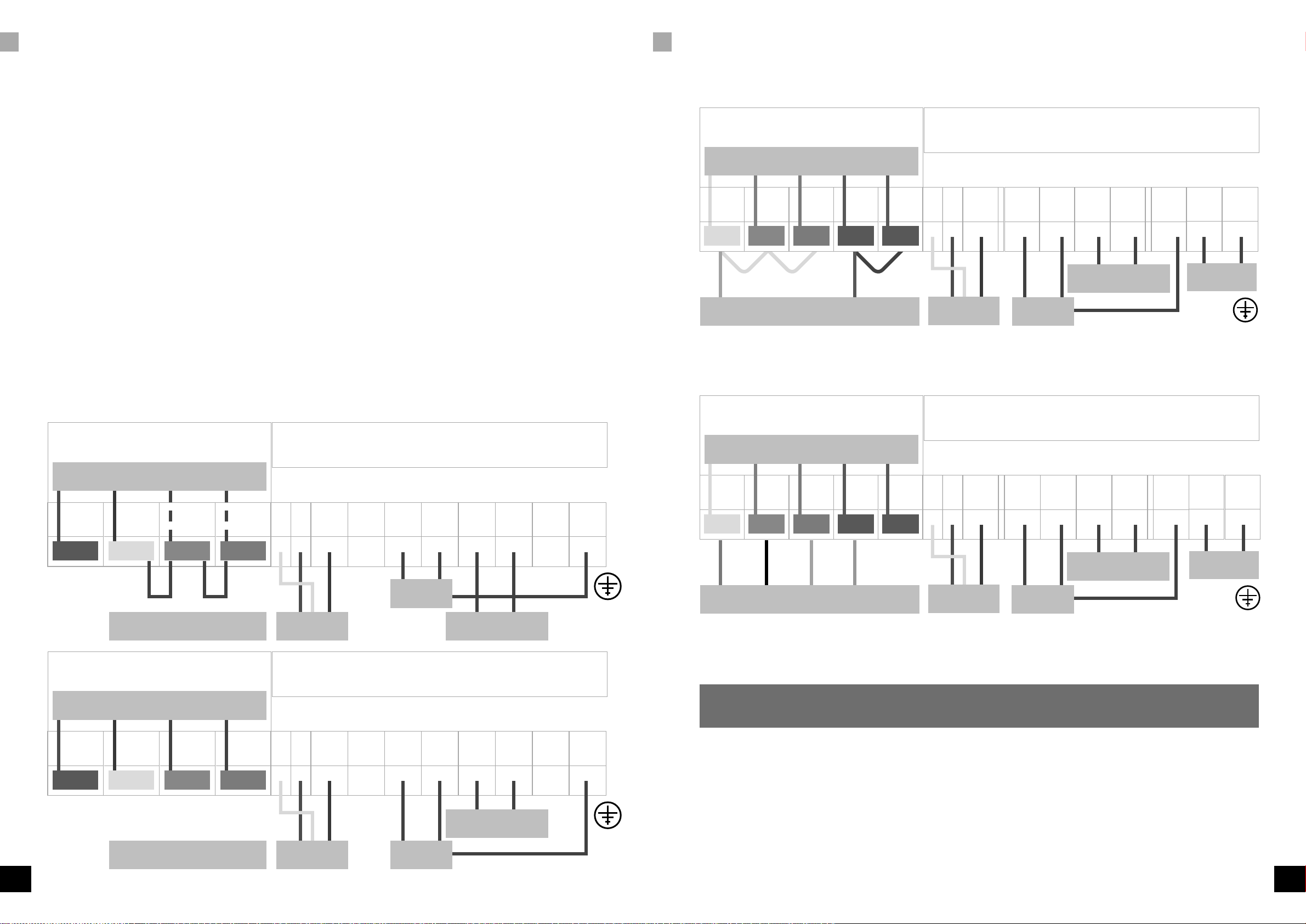
D:10 Timer port
If D:10=0, ports 15 and 16 will interrupt the High Temperature alarm. If D:10=1, the high temp alarm will not occur
through these contacts. If D:10=1, port 16 is common and ports 16 & 17 will be each other's alternate contacts. The
clock of the OptiClimate (OC) will operate these make-and-break contacts and the clock/timer of the OC can replace
the clock on the control panel. The lamps will operate synchronous with the cooling mode of the OC. To install a High
Temperature safeguard, contact 16 should be aligned with the alarm port on the printed circuit-board. If there is a
High Temperature alarm, this alarm will interrupt the timer’s signal and the temperature safeguard will still operate. The
setting of the alarm port should then be the standard setting (0 = N.C.).
D:11 Hysteresis of the temperature
Using this setting, you can adjust the hysteresis (bandwidth) of the temperature control. This is the temperature difference
required to switch the compressor on and off.
Setting: D:11 = 2 means the hysteresis is 2. This is the default setting.
The hysteresis can be set from 1°C to 4°C in steps of 0.5°C. If, for example, the day temperature is set to 28°C and the
hysteresis to 2°C, the unit will start to cool at 29°C and stop cooling at 27°C. To shorten the hysteresis effectively, the
resting time of the compressor should also be reduced. (D:27)

18 19
ENEN
blank
blank
SETTINGS (SETUP) FAULT ANALYSIS AND ERROR MESSAGES
D:12 Minimum adjustable heating temperature
Using this setting, you can change the minimum adjustable heating temperature.
The adjustable values in D:12 are: default = 16°C, max. = 20°C, min. = 10°C.
D:13 Maximum adjustable heating temperature
Using this setting, you can change the maximum adjustable heating temperature.
The adjustable values in D:13 are: default = 35°C, max. = 50°C, min. = 25°C.
D:14 Minimum adjustable cooling temperature
Using this setting, you can change the minimum adjustable cooling temperature.
The adjustable values in D:14 are: default = 16°C, max. = 20°C, min. = 10°C.
D:15 Maximum adjustable cooling temperature
Using this setting, you can change the maximum adjustable cooling temperature.
The adjustable values in D:15 are: default = 35°C, max. = 35°C, min. = 25°C.
D:16 Anti-freeze protection of the cooling water
Using this setting, you can determine at which temperature the Anti-Freeze Alarm is activated. The adjustable values in
D:16 are: default = 3°C, max. = 0°C, min. = 10°C.
D:17 Anti-freeze protection of the cooling block
Using this setting, you can determine at which temperature the Anti-Freeze alarm of the cooling block is activated. The
settings in D:17 are: default = 0°C, max. = 5°C, min. = -2°C.
D:18 Cooling water temperature too high
Using this setting, you can determine at which temperature the Cooling water temperature too high alarm is activated.
The settings in D:18 are: default = 57°C, max. = 60°C, min. = 40°C.
D:19 Cooling water temperature too low
Using this setting, you can determine at which temperature the Cooling water temperature too low alarm is activated.
The settings in D:19 are: default = 4°C, max. = 0°C, min. = 10°C and 1°C.
D:20 Not applicable
D:21 Cooling block too hot
Using this setting, you can determine at which temperature the Cooling block too hot alarm is activated. The settings
in D:21are: default = 4°C, max. = 0°C, min. = 10°C and 1°C. To activate the alarm, the temperature has to be too
high for a certain period of time. The time is determined by D:22. D:21 and D:22 jointly determine when Error 11 is
activated.
D:22 Duration of cooling block too hot
Using this setting, you can determine how long it takes before a Cooling block too hot alarm is given. The settings in
D:22 are 30mins (standard), 40mins (maximum), 20mins (minimum).
The temperature level is determined by D: 21. D:21 and D:22 jointly determine when E:11 is activated.
D:23 Temperature of compensating the room temperature sensor
Using this setting, you can calibrate the room temperature sensor. The setting can be changed if the indication on the
display does not correspond with reality. The settings in D:23 are: default = 0°C, max. = 5°C, min. = -5°C and can
be set in 0.5°C increments.
D:24 Temperature of compensating the cooling block temperature sensor
Using this setting, you can calibrate the cooling block temperature sensor. The settings in D:24 are: default = 0°C, max.
= 5°C, min. = -5°C and can be set in 0.5°C increments.
D:25 Temperature compensation of the cooling water temperature sensor.
Using this setting, you can calibrate the cooling water temperature sensor. The settings in D:25 are: default = 0°C, max.
= 5°C, min. = -5°C and can be set in 0.5°C increments.
D:26 Temperature compensation of the Dual Room temperature sensor
Using this setting, you can calibrate the second room temperature sensor in the Dual Room conguration. The settings
in D:26 are: default = 0°C, max. = 5°C, min. = -5°C and can be set in 0.5°C increments.
D:27 Resting time of the compressor
Using this setting, you can adjust the resting time between Compressor Off and Compressor On.
Setting: D:27 = 15 means the idle time is 15 seconds. This is the default setting. This setting may be used if the
temperature values in the room change too much because of the time that the compressor is in idle mode.
D:28 Water Leakage Alarm on/off.
Using this setting, the water leakage alarm can be switched on or off. If D:28 is set to 1, the alarm is on. If D:28 is set
to 0, the alarm is off.
D:29 Display lighting
Using this option, you can switch the lighting in the display of the remote control on and off.
0 = Automatic (default)
1 = Always on
D:30 Beep on/off
The tone that is generated when the remote control is used can be turned on and off.
0 = off
1 = on
D:31 Fahrenheit/Celsius
The temperature shown on the display can be displayed in Fahrenheit and Celsius
0 = Celsius
1 = Fahrenheit
D:32 Super dehumidication (only pro4)
This function allows for dehumidication in the day mode without a demand for cooling.
0= super dehumidication off.
1= super dehumidication on.
Inspection and maintenance
Frequently check whether all couplings of the water connections are properly tightened. Also check that there are no
leaks. Frequently check whether there is no thickening of the black coil (black block on the brass valve) of the brass
solenoid valve (water seal). In case of poor contact (moist contact), the coil can become too hot and expand. If this is
not xed, the coil can burn out and the solenoid valve will no longer open.
The dust lter at the backside of the unit should be checked every 10-12 weeks for dust accumulation. If the lter has a
layer of dust, the dust should be removed using a vacuum cleaner.
The carbon lter should be replaced every 10-12 weeks in order to guarantee proper operation of the unit. This is
essential and should not be forgotten! If this is not carried out, the lter will break down sooner than normal. To replace
the carbon lter, you rst have to remove the dust lter.
Note : If you want to work with a humidier, make sure that it is connected to a reverse osmosis lter or scale lter. Fan
faults caused by lime deposits are not covered under the warranty.
If the dust lter is still clogged with white particles when using a humidier in conjunction with a scale lter, then an
osmosis lter is required. The water is too hard to use with a scale lter. There is no need to use a humidier if the space
is not too large.

20 21
ENEN
blank
blank
FAULT ANALYSIS AND ERROR MESSAGES FAULT ANALYSIS AND ERROR MESSAGES
Fault analysis and error messages
If the unit does not switch on and the remote control display and the LEDs on the printed circuit-board are off, most
likely there is no power supply. It is also possible that the internal fuse has blown. This fuse is located near the printed
circuit-board in a synthetic housing.
If there is power (the LED on the printed circuit-board ashes and the remote control display shows E:01), but the unit
does not switch on, two of the three phases should probably be switched. It does not matter which ones of the three
phases are switched.
If the fuse automat burst when the unit has to start cooling, most likely a fuse of the wrong value or incorrect type was
installed. Check the technical specications (page 8) for the correct details.
If the unit makes strange noises or is cooling poorly, check the manometer to ensure that the pointer is not pointing too
far to the right from the centre of the screen and check that the water temperature does not exceed 50°C. If that is the
case, make sure that the unit receives more water and check whether the pointer of the manometer drops. Subsequently,
set the manometer as described in the Settings section on page 14.
If water continues to ow through the apparatus while the unit is off, it might be possible that the magnetic valve is
mounted incorrectly. Check the arrow on the brass housing. If water drips from the sides of the unit, you have a problem
with the condensation water drainage. Check whether the unit has sufcient fall (see the Mounting section) using a
spirit level. It is also possible that the condensation hose has too many loops/bends or is blocked.
Fault code list
Error 01 = Usually means that the phases are crossed (reversal). Only active in the 15000 series.
Two of the three phases - it does not matter which - should probably be switched. If the unit has operated before,
the phases are connected properly. You may have a problem with the power supply (voltage). You can check this by
observing which LED is burning on the little white cupboard in the top of the electrical compartment.
Over voltage = Voltage is too high
Low voltage = Voltage is too low
Phase loss = Phase is interrupted
Reversal = Phase sequence is incorrect (crossed)
Normal = Phases are connected properly and the voltage is correct
Error 02 = Condensate does not drain.
Check the condensation drain for blockage and make sure the unit has sufcient fall towards the condensation drain.
Error 03 = Drain water temperature is higher than 57°C.
If the error message appears when the unit is already operating for a while, then too little or no water ows through the
unit. The pressure may be set too high.
See the Setting the cooling capacity section (page 14) for the correct ow.
Error 04 = Ambient temperature is too low
The unit is placed in a cold environment, causing the risk of freezing. The room in which the OptiClimate is installed
should be warmer than 4°C.
Error 05 = Ambient temperature sensor is not connected or is defective
Error 06 = Cooling block temperature sensor is not connected or is defective
Error 07 = Return cooling temperature sensor is not connected or is defective
Error 08 = Water leakage safeguard is active.
There is a water leak. Repair the leak and dry the end of the sensor.
In Dual Room systems, error 08 indicates a problem with the second temperature sensor.
Error 09 = Thermal safeguard of the compressor is activated.
The compressor consumes too much current. Contact the Technical Service department, if the thermal safeguard jumps
again after resetting. The thermal safeguard is located at the left-hand side near the printed circuit board in the electrical
compartment.
Error 10 = Anti-freeze safeguard, the temperature of the cooling block is too low.
If the cooling block is colder than 0°C, it can freeze up. The unit stops cooling and starts to defrost. Most likely too much
water ows through the unit. This causes the unit to have too much cooling capacity. The minimum pressure is 1.3MPa.
You might have to increase the pressure slightly to reduce the cooling capacity. See the Settings section to remedy this.
The dust/carbon lters may also be blocked or the outlet is too scanty/tight (too few holes or the hose is too thin). The
result is that the unit cannot get rid of its cold air.
Error 11 = Poor cooling.
There is no proper cooling. There may be a leak in the cooling system and it needs to be repaired. The condenser of
the compressor may also be faulty.
Error 12 = High pressure protection.
If this error message appears, most likely water does not ow through the unit. This should be resolved immediately,
because the unit cannot get rid of its hot air and the pressure of the cooling system will repeatedly increase too much.
It is also possible that the unit gets too little water. See the Setting the cooling capacity section (page 14) for
the correct ow.
If water does not ow through the unit and the taps and solenoid valve are open, the heat exchanger might also be
clogged due to the use of well or polluted water. Check the lter in the inlet.
Error 13 = Low pressure protection.
Check the manometer when the unit is off. Is the pressure lower than 4bar/0.4Mpa? If yes, there is a leak in the cooling
system and it must be repaired.
Error 14 = Current interruption alarm.
The unit is deprived of current. This alarm, which is only visible in the alarm history at the bottom of the display,
indicates that there was a problem with the current.
Error 15 = High ambient temperature safeguard is active.
As soon as the ambient temperature drops below the set day temperature, the unit will switch on the sources of heat
again and the error code will disappear. The number 15 will, however, continue to be shown in the log at the bottom
of the display. You can delete this by pressing and holding the Rkey.
Error 16 = Water leakage safeguard is active.
There is a leak. The external water sensor (the 5m long wire with two blank cores at the end) makes contact with water
and the water supply is closed. Once the leak is repaired, you have to press the ON/OFF key and the unit will
operate normally. Please contact your supplier in case of any other error message.
Error 17 = Intake air sensor faulty or not connected
Error 18 = Outlet air sensor faulty or not connected
Error 19 = Temperature low pressure sensor faulty or not connected

22 23
ENEN
blank
blank
OPTIONALLY AVAILABLE / INFORMATION LEAFLET PRO4 FAULT CODE OVERVIEW
Vibration isolation springs
Vibration absorbers for extra quiet rooms. These absorbers are meticulously calculated to bear the unit’s weight and
ensure nearly 100% contact insulation. No other solutions on the market offer a similar level of contact insulation.
Noise damping plate with adhesive layer (2 pieces)
Anti-vibration plates; absorbing plates for extra quiet rooms. These plates can be glued to the at panels of the unit to
limit noises radiated by the unit to a minimum.
Condensation water lift pump
Discharge head up to 4 metres. This pump is often used if there is no drain for the condensation water in the vicinity or
if the unit is placed lower than the drain. 6mm PVC hose connection. Comes with a 5m hose.
Three-way valve
Comes with servomotor and additional temperature sensor of 10 metres. This valve enables cooling two rooms 12h by
12h if the Dual Room function is switched on. Each room has its own sensor and it scans the room where the cooling
is activated. The High Temperature Safeguard will be active for both rooms simultaneously.
Plenum box
This box can be installed at the backside of the OptiClimate, so that the unit can be placed outside the room. One
to three hoses can be connected to the plenum box to suck out the warm air from the room. Always measure the
dimensions of the suction hoses as large as possible.
Carbon lters (3 pieces)
See also Inspection and Maintenance
Siphon
Could be needed when there's too much underpressure in the intake system.
Information leaet PRO4
The PRO4 can also dehumidify the room in the day mode when no cooling is required. To activate this function option
D:32 can be adjusted in the menu. During dehumidication in the day mode no water is consumed if no cooling is
required.
1) Hold the S key pressed. D:01 appears
2) Press and release repeatedly the S key until D:32 appears.
3)Using the arrow keys choose between 0 and 1
4)Conrm this with the on/off key.
D:32 = 0 dehumidication in day mode is off.
D:32 = 1 dehumidication in day mode is on.
The standard setting of D:32 = 0.
At night the dehumidication is controlled by the automatic moisture meter. In day mode during cooling the unit always
dehumidies (scientic phenomena). When the units dehumidies at night no water will be consumed. The water
released during dehumidication is recycled in the unit ensuring that the electric heating will also not activate.
The electric heating elements will only be activated if the night temperature drops below the preset night temperature.
Upon installation of a PRO4, the electric solenoid valve should be connected, otherwise the unit WILL consume water
during dehumidication.
Keep this error list in the vicinity of the OptiClimate.
E:01 Phase monitor (only for 15000 pro3)
E:02 Condensation drain
E:03 Drain water temperature too high. (>57°C)
E:04 Ambient temperature too low (<4°)
E:05 Room temperature sensor not connected
E:06 Cooling block temperature sensor not connected
E:07 Return water temperature sensor not connected
E:08 Room temperature sensor not connected (Dual Room)
E:09 Compressor motor thermal safeguard
E:10 Cooling block anti-freeze safeguard
E:11 Faulty or no cooling alarm
E:12 High pressure safeguard (cooling system)
E:13 Low pressure safeguard (cooling system)
E:14 Power interruption
E:15 High temperature safeguard
E:16 Water leakage safeguard
E:17 Air intake sensor
E:18 Outlet air sensor
E:19 Low-pressure refrigerant temperature sensor

Amsterdam, the Netherlands
www.opticlimate.nl
MADE IN HOLLAND
OptiClimate is a registered trademark of
airSupplies
V04052016
Other manuals for PRO3 Series
4
This manual suits for next models
13
Table of contents
Other OPTICLIMATE Air Conditioner manuals
Popular Air Conditioner manuals by other brands

Daikin
Daikin FXHQ32MVE installation manual

Mitsubishi Electric
Mitsubishi Electric Mr. Slim PK-2.5FLA installation manual

Mitsubishi Electric
Mitsubishi Electric NTXMMX A AA Series Service manual

Fujitsu
Fujitsu General ASHG30KMTA Design & technical manual

Samsung
Samsung AVXWBH028EE user manual

Dometic
Dometic B2600 Operation, maintenance and installation manual