Opticom Technologies Inc. USA Sales: BattleCreek, Michigan: 800-578-1853
www.opticomtech.com Canada: Head Office(Vancouver): 855-569-3240
www.toughestvideocamera.com
March 2016
Installation Manual
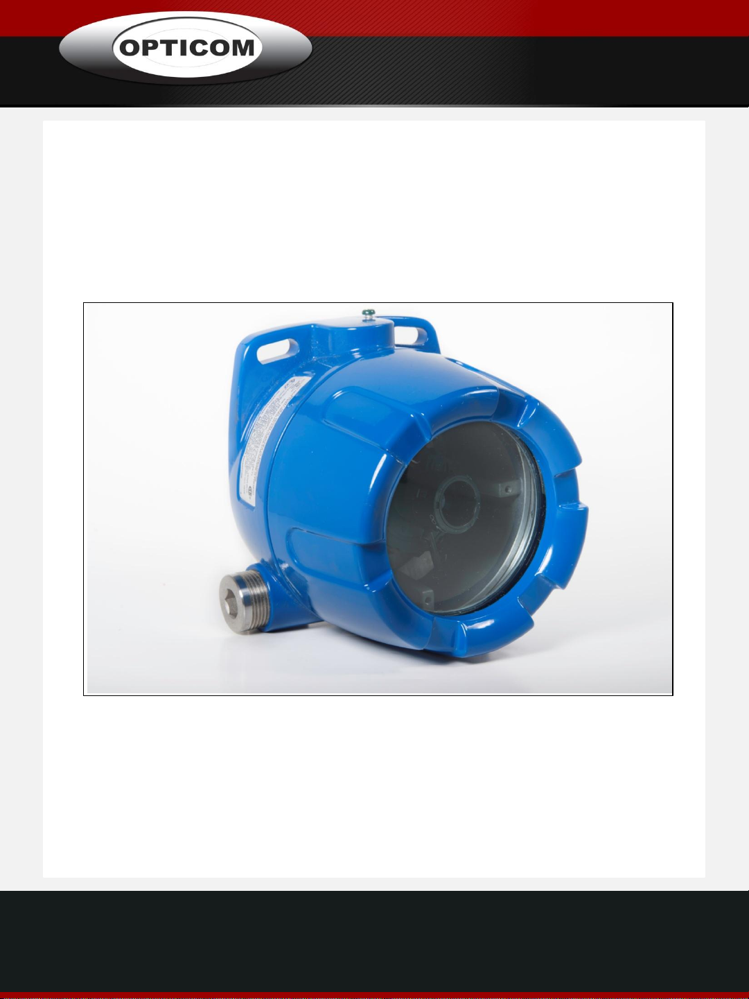
CC03-2VF Camera
IMPORTANT SAFETY INSTRUCTIONS
1. Read and keep these instructions. Heed all warnings.
2. Do not use this apparatus near water.
3. Clean only with dry cloth.
4. Do not block any ventilation openings. Install in accordance with manufacturer instructions.
5. Do not install near any heat sources such as radiators, heat registers, stoves or other
apparatus (including amplifiers) that produce heat.
6. Protect the power cord from being walked on or pinched particularly at plugs, convenience
receptacles, and the power where they exit from the device.
7. Refer all servicing to qualified service personnel. Servicing is required when the apparatus
has been damaged in a way, such as power-supply cord or plug is damaged, liquid has been
spilled or objects have fallen into the apparatus, the apparatus has been exposed to rain or
moisture,does not operate normally or has been dropped.
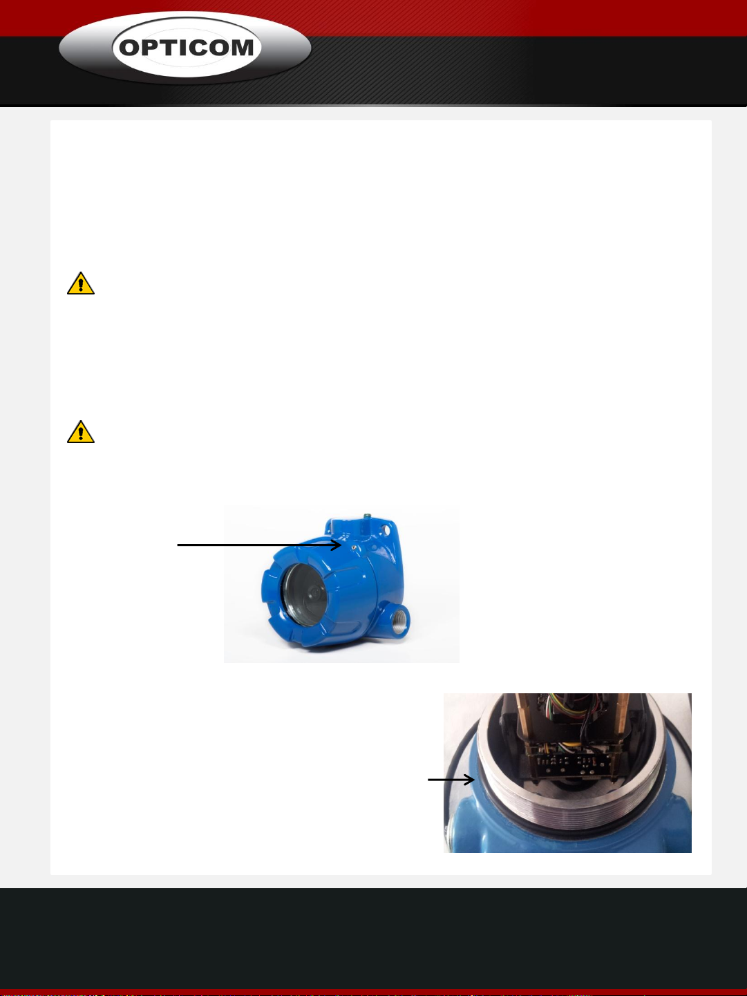
8. To reduce the risk of ignition of hazardous atmospheres, disconnect the equipment from the
supply circuit before opening. Keep assembly tightly closed when in operation.
9. The maximum ambient temperature range is –40° to 122°F (–40° to 50°C).
10. Installation should be done only by qualified personnel and conform to all local codes.
11. Use only installation methods and materials capable of supporting four times the maximum
specified load.
WARNING: To reduce the risk of ignition of hazardous atmospheres, disconnect the device
from the supply circuit before opening. Keep assembly tightly closed when operating.
WARNING: To reduce the risk of ignition of hazardous atmospheres, conduit runs must have
a sealing fitting connected within 2 inches of the enclosure.
TO REDUCE THE RISK OF IGNITION DO NOT OPEN WHEN AN EXPLOSIVE GAS ATMOSPHERE
MAY BE PRESENT.
DISCLAIMER: Opticom Technologies Inc. will not be responsible for injuries or damages resulting
from the improper installation or use of any product sold by Opticom Technologies Inc. their
agents, distributors or dealers.