About This Document
Before installing and using this unit, please read
this manual carefully. Be sure keep it handy for
later reference.
Safety Notices Used in This Manual
Caution! –Indicates a potential hazard that can
damage the product.
Important! –Indicates a hazard that can seriously
impair operation.
Do not proceed beyond any of the above notice until
you have fully understood the implications.
Important Safety Rules
WARNING: DO NOT OPEN WHEN AN EXPLOSIVE
ATMOSPHERE IS PRESENT
WARNING: DO NOT OPEN WHEN ENERGIZED
The manufacturer declines all responsibility for
any damage caused by an improper use of the
appliances mentioned in this manual. Furthermore,
the manufacturer reserves the right to modify its
contents without any prior notice. The
documentation contained in this manual has been
collected with great care, the manufacturer,
however, cannot take any liability for its use. The
same thing can be said for any person or company
involved in the creation and production of this
manual.
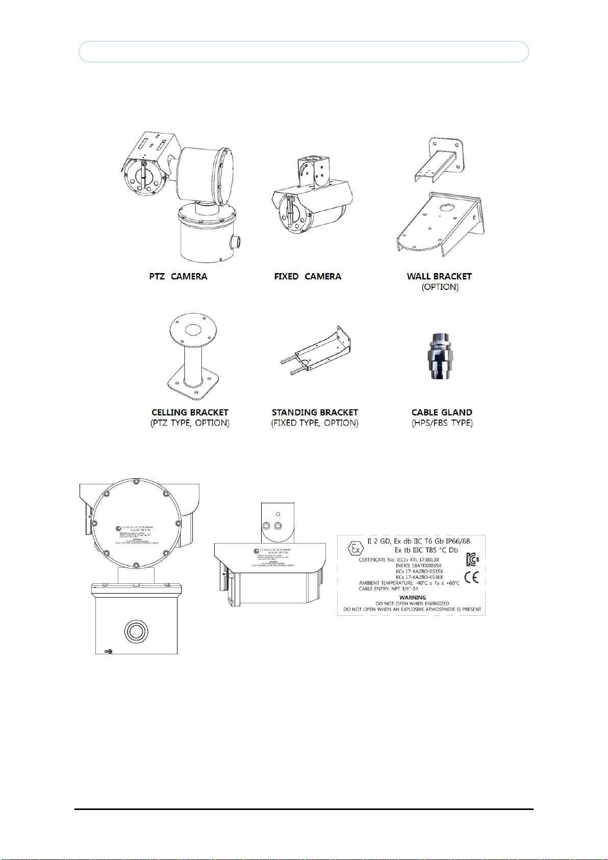
•Ex db IIC T6 Gb
•Ex tb IIIC T85 ˚C Db
•IECEx KTL 17.0013X
•INERIS 18ATEX0035X
(Not applicable for models with last model code
FN, TN, FP, TP)
•IEC 60079-0: 2011
•IEC 60079-1: 2014
•IEC 60079-31: 2013
•EN 60079-0 : 2012/A11 : 2013
•EN 60079-1 : 2014
•EN 60079-31:2014
•Degree of Protection: IP66/68
The verification of the protection degree IPX8
corresponds to an immersion under 1.2 meters of
waters during 30 minutes.
•Read these instructions.
•Keep these instructions.
•Heed all warnings.
•Follow all instructions.
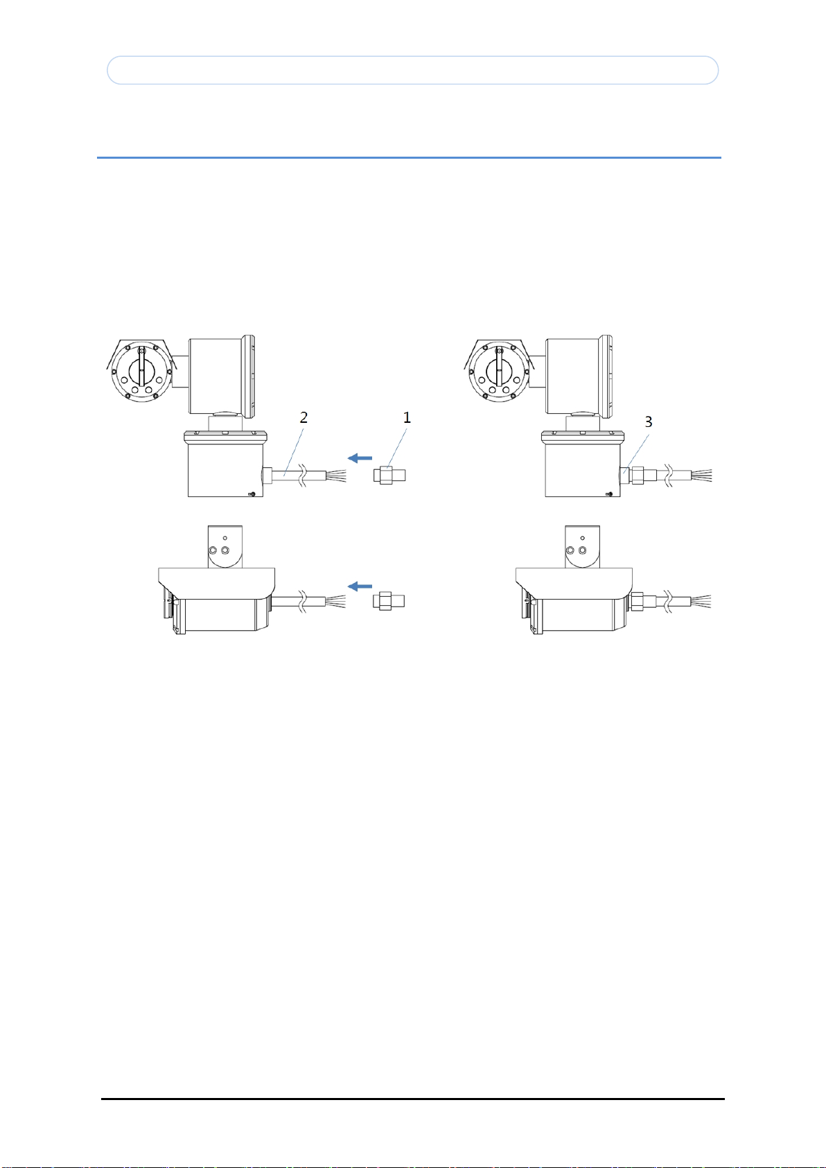
•To reduce the risk of ignition of hazardous
atmospheres, disconnect the equipment from the
supply circuit before opening. Keep the product
tightly closed when in operation.
•Choose an installation surface that is strong
enough to sustain the weight of the device,
also bearing in mind particular environmental
aspects, such as exposure to strong winds.
•Since the user is responsible for choosing the
surface to which the unit is to be anchored,
wedo not supply the fixing devices for
attaching the unit firmly to the particular
surface. The installer is responsible for
choosing fixing devices suitable for the
specific purpose on hand. Use methods and
materials capable of supporting at least 4
times the weight of the device.
•For technical services, consult only and
exclusively authorized technicians.
•A power disconnect device must ne included in
the electrical installation, and it must be
very quickly recognizable and operated if
needed.
•The equipment is certified for use in ambient
temperatures from -40°C to +60°.
•This device is remotely controlled and may
change position at any time. It should be
installed so that no one can be hit by moving
parts. It should be installed so that moving
parts cannot hit other objects and create
hazardous situations.
•The dimensions of flameproof joints are
different from the values specified in the
tables of the IEC 60079-1 or EN 60079-1
standard.
•The flameproof joints are not intended to be
repaired.
Legal Considerations
Camera and audio surveillance can be prohibited by
laws that vary from country to country. Check the
laws in your local region before using the product
for surveillance purposes.
Electromagnetic Compatibility
This equipment generates uses and can radiate radio
frequency energy and, if not installed and used in
accordance with the instructions, may cause harmful
interference to radio communications. However,
there is no guarantee that interference will not
occur in a particular installation. If this
equipment does cause harmful interference to radio
or television reception, which can be determined by
turning the equipment off and on, the user is
encouraged to try to correct the interference by
one or more of the following measures: Re-orient or
relocate the receiving antenna. Increase the
separation between the equipment and receiver.
Connect the equipment to an outlet on a different
circuit to the receiver. Consult your dealer or an
experienced radio/TV technician for help. Shielded
(STP) network cables must be used with this unit to
ensure compliance with EMC standards.
Liability
Every care has been taken in the preparation of
this manual; please inform your local OPTICOM
office of any inaccuracies or omissions. OPTICOM
INTERNATIONAL INC. cannot be held responsible for
any technical or typographical errors and reserves
the right to make changes to the product and
manuals without prior notice. OPTICOM INTERNATIONAL
INC. makes no warranty of any kind with regard to
the material contained within this document,
including, but not limited to, the implied
warranties of merchantability and fitness for a
particular purpose. OPTICOM INTERNATIONAL INC.
shall not be liable nor responsible for incidental
or consequential damages in connection with the
furnishing, performance or use of this material.