Optimal 2500 User manual

O P E R A T I N G M A N U A L
FOR
TREE SPADE OPTIMAL 2 5 0 0
MOUNTED ON VOLVO A25 D
Manufacturer: Distributor:
Optimal-Vertrieb Opitz GmbH Prichard's Nursery Equipment LLC
Eysoelden M 41 P.O. Box 549
91177 Thalmaessing Portland, TN 37148
Germany U.S.A.
Phone: ++ 49 - 9173 - 79 18 0 Phone: (423) 326 - 0753
Fax: ++ 49 - 9173 - 79 18 49 Fax: (615) 323 - 7667
eMail: info@opitz-optimal.com eMail: sales@optimaltreespades.com
web: www.opitz-optimal.com web: www.optimaltreespades.com
Serial-Number : 250021

- 2 -
C O N T E N T S
page
Safety Instructions 3
1. Operating Specifications 4
2. Hydraulic Supply 5
3. Operation and Transport 6
4. Care and Maintenance 14
5. Lubrication chart 15
6. Hydraulic System 17
7. Wiring Diagram 19
8. Spare Parts List

- 3 -
Safety Instructions for OPTIMAL Tree Spade
The operator and his assistant(s) must have read and understood the Operating
Manual before running the tree spade. Furthermore, the operator must be
experienced in driving the hauler truck and he must have studied the relevant
truck manual.
Before starting operations, bolts and hydraulic fittings must be checked to make sure
they are free of damage and well tightened.
Defective or loose hose pipes might cause serious injuries and therefore must be
replaced immediately.
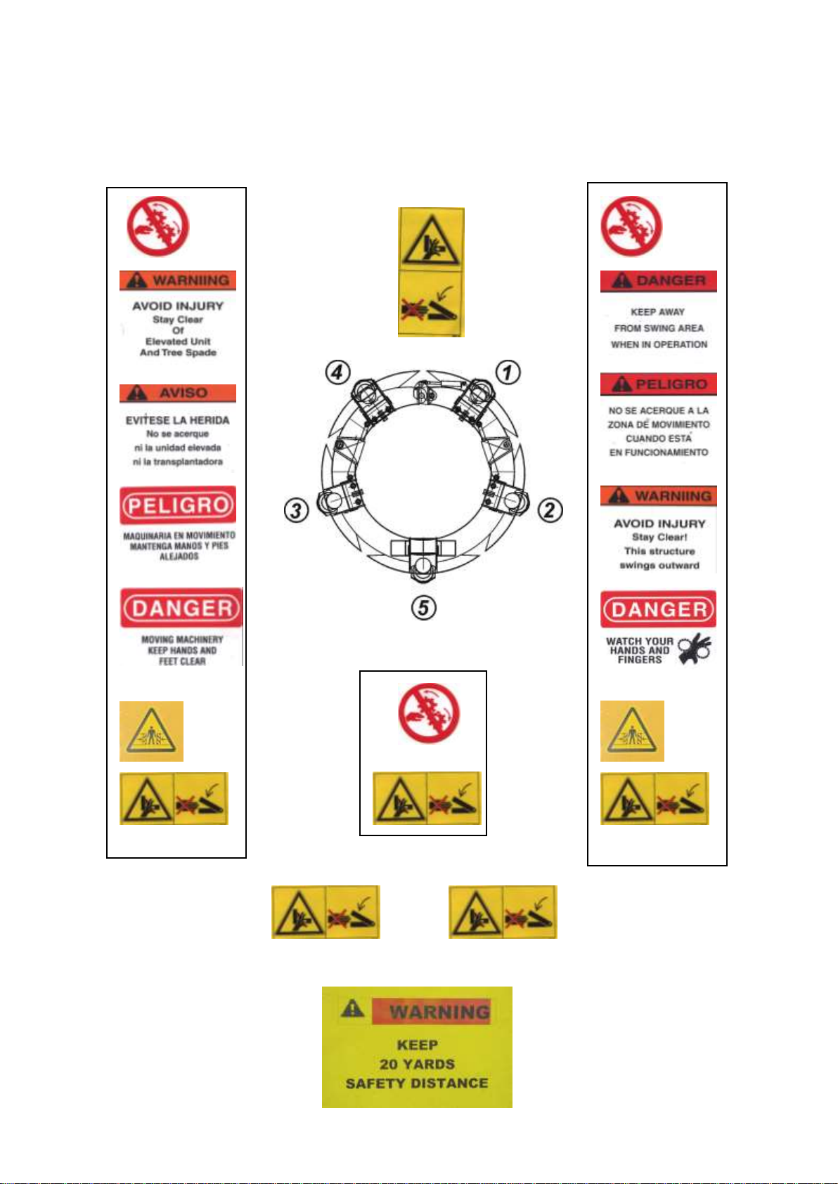
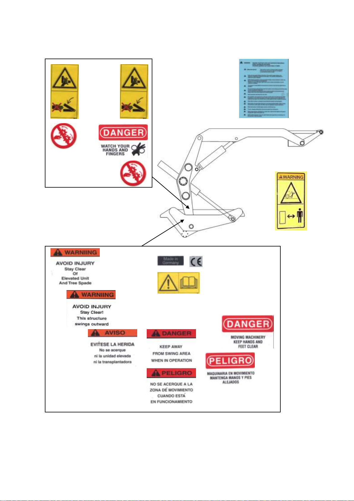
The operator is responsible for ensuring that no person is near the tree spade when
in operation; in particular, no one should be standing underneath the raised tree spade or
near shearing and pinching areas, or near the gate, or near blades or near
hydraulic components.
We are advising the user that due to their functional positions and movements the
danger areas cannot be furnished with protective guides.
When sight is limited, an assistant must direct the operator by hand signals.
When driving, the tree spade should be in the lowest possible position. When moving
and working on public roads, the relevant traffic rules and regulations must be
adhered to.
When doing cleaning, maintenance or repair work, lower the tree spade to the ground
and stop the engine of the power unit.
The tree spade must be inspected by an expert on operational reliability annually.
All hydraulic hose pipes must get replaced every six years.
Do not modify the equipment unless the manufacturer has given his approval. Use original
spare parts only.
When digging it might happen that a stone gets caught between two blades and the blades
get bent. This causes tremendous tension in the steel blades. Place the digging head again
into the planting hole and retract the blades. Thereby the stone will come loose. The blades
got a high degree of bending strength and they will regain their former shape. After the stone
has been released, the root ball can be dug again.
Do not try to release the stone by means of a crow bar or other tools!
The operator must be sure that the ground he is going to dig is free from any underground
installations such as cables, pipes or any other utilities or dangerous matter. Damaging such
underground installations or matter is dangerous and might result in serious injury or death.
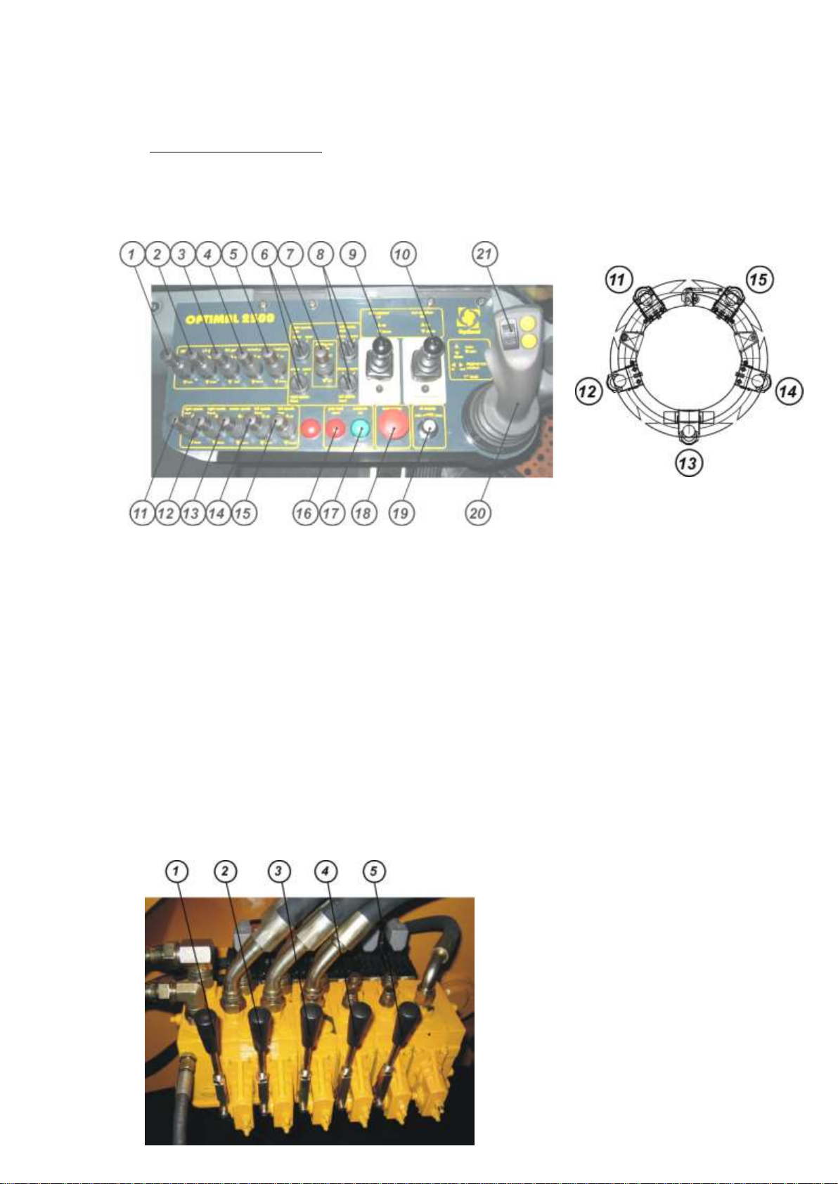
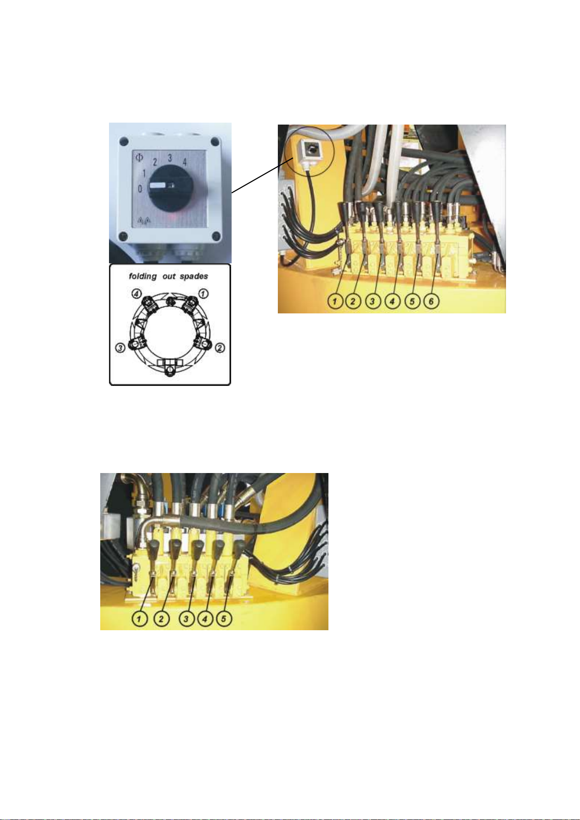
Before commencing tree spade operation, switch on hydraulic pump. The switch is marked with
an arrow on illustration 1 page 6. If the pump is not switched on, the hitch oscillating brake is not
activated and the truck might overturn.
When travelling, the hydraulic pump should be switched off.

- 3A -
Tower 4: Tower 1:
Lock Cylinder
Tower 2,3,5:
Gate Cylinder Gate Cylinder
Main Frame, right and left

- 3B -
main lift arm: drivers cabin:
rear stabilizer:
frame:

- 4 -
1. Operating Specifications
Description Tree Spade OPTIMAL 2 5 0 0
serial-Number 250021
year of production 2004
capacity upper root ball diameter 250 cm 98“
root ball depth 150 cm 59“
Dimensions of the height 290 cm 114“
digging head width, gate closed 250 cm 98“
width, gate open 304 cm 120“
clearance between open gate 162 cm 64“
inner diameter of frame 178 cm 70“
working height 303 cm 119“
weights digging head 5750 kg
superstructure 7800 kg
hydraulics hydraulic working pressure 200-220 bar 2900–3190 psi
oil flow 80–100 l/min 21,1–26,4 GPM
spade pressure at 200 bar 15000kg/blade 33000lbs/blade
controls electro-hydraulic valves, double acting,
activated either from
control panel in the driver’s cabin by means of levers,
joystick and switch, or
from valve banks at the base frame and the digging head by
means of manual valve levers
application for moving and transplanting trees with a trunk diameter of
up to approx. 25 cm (10”)

- 5 -
2. Hydraulic Supply
2.1 All working movements of the tree spade are performed hydraulically. The hydraulic
pressure is provided by a hydraulic pump integrated in the Volvo truck A25 D.
The truck and the tree spade work with biological hydraulic oil PANOLIN HLP SYNTH
(Synth HLP 46) and it should never be mixed with a petroleum-based hydraulic oil. For
specifications of hydraulic oil, please refer to annex.
In order to avoid any damages to the hydraulic system and related components, samples
of the hydraulic oil must be taken regularly. This is extremely important because regular
sampling is precondition for any damages claim.
Impurities in the oil must not exceed purity class 19/15/11 as per ISO 4406.
The first sampling and examination must be made after 50 working hours, each following
sampling becomes due after every 1000 working hours.
The intervals for changing the hydraulic oil must be strictly observed, otherwise the
durability of sealing components and hose pipes cannot be guaranteed.
In case the PANOLIN HLP SYNTH-run hydraulic system is changed on a petroleum-
based hydraulic oil, the instructions of the truck manufacturer are to be followed.
2.2 For technical information on the hydraulic pump such as filling quantities and servicing
intervals, please refer to the instruction manual of the truck manufacturer.
2.3 All working movements of the tree spade can be controlled either from the control panel
installed inside the driver’s cabin or they can be actuated by the manual valves installed at
the base frame of the superstructure or the digging head respectively.

- 6 -
3. Operation and Transport
IMPORTANT The operators must work absolutely reliable. Before they start with production
work, they must have studied these instructions thoroughly.
The following safety instructions must always be observed:
It is the operators responsibility to ensure that no persons are in the danger area of
the tree spade. In particular, no one should be underneath the raised tree spade or
near areas where work functions might cause shearing and pinching injuries.
Do not perform any manual work on trees which are inside the tree spade. In
particular, do not work with hand or feet inside the machine. Do not tie the tree
when it is inside the digging head.
When sight is limited, an assistant must direct the driver by hand signals.
Before starting operations, bolts and hydraulic fittings must be checked to make
sure they are well tightened and free of damage.
When moving and working on public roads, the relevant traffic rules and
regulations must be adhered to.
IMPORTANT Before commencing tree spade operation, switch on the hydraulic pump. The
switch is located in the drivers cabin on the panel as marked with an arrow on
Illustration 1.
It is of utmost importance that the hydraulic pump is running. Otherwise the hitch
ocillating brake is not activated and the truck might overturn!
When travelling, the hydraulic pump should be switched off again.
Illustration 1

- 7 -
3.1 The Control Components
All directions (RH, LH) are given as seen from the control panel in driver`s cabin.
3.1.1 Control Panel Inside the Driver’s Cabin Location of Spades
1) gate lock –unlock / lock 11) left spade, rear –up / down
2) LH gate –open / close 12) left spade, front –up / down
3) RH gate –open / close 13) center spade –up / down
4) root ball pad LH –up / down 14) right spade, front –up / down
5) root ball pad RH –up / down 15) right spade, rear –up / down
6) preselect folding out spades - LH rear / front 16) indicator light –gate lock open
7) folding out spades –in / out 17) indicator light –controls on
8) preselect folding out spades - RH rear / front 18) emergency off
9) rear stabilizer LH –up / down 19) oil supply min/max
10)rear stabilizer RH –up / down 20) ▲ main lift arm – up
▼ main lift arm – down
◄► digging head rotation – in / out
21) ▓ articulated lift arm – up / down
3.1.2 Valve Bank on the Base Frame
1) main lift arm –up / down
2) digging head rotation –in / out
3) articulated lift arm –up /down
4) rear stabilizer LH –up / down
5) rear stabilizer RH –up / down

- 8 -
3.1.3 Valve Bank at the Digging Head (6 functions)
1) LH gate –open / close
2) root ball pad LH –up / down
3) root ball pad RH –up / down
4) RH gate –open / close
5) gate lock –unlock / lock
6) folding out spades –in / out
3.1.4 Valve Bank at the Digging Head (5 functions)
1) left spade rear –up / down
2) left spade front –up / down
3) right spade rear –up / down
4) right spade front –up / down
5) center spade –up / down

- 9 -
3.2 Operating Procedure
3.2.1 Extend both rear stabilizers before lowering the digging head to the ground
control panel, lever 9 and 10 ▼"down".
The truck should be positioned on level ground, if possible.
In case the rear stabilizers do not reach down to the ground, the inner square pipe can be
lowered by removing lock pin A (ill. 2) and extend the stabilizer (ill. 3) The stabilizer can be
mechanically adjusted to 4 different sizes. When having selected the required extension
size, lock pin A is put back in place.
IMPORTANT: When travelling, the stabilizers must be always in the highest position
(ill.2) to grant sufficient clearance to the ground.
A
Illustration 2 Illustration 3
3.2.2 In order to lower the digging head, the main lift arm and the articulated lift arm must be
raised and the digging head must be rotated out into a vertical position.
control panel: joystick 20, main lift arm ▲"up"
control panel: joystick 21, articulated lift arm ▲"up"
control panel: joystick 20 digging head rotation ►"out"
The functions main lift arm▲"up" , articulated lift arm ▲"up" and digging head ►"rotate
out“ must be actuated in repeating succession until the digging head is in a vertical
position and it got sufficient clearance to the base frame. When rotating the digging head
(digging head rotation ►"out") make sure it does not touch the base frame, nor the
cylinders, nor the main lift arms.
When the digging head is in a vertical position it must be lowered carefully:
control panel: joystick 20, main lift arm ▼"down"
Make sure the digging head does not touch the rear of the truck. If necessary, do correct
the position.
Now the 5 spades must be retracted:
control panel, levers 11,12,13,14 and 15, spades ▲"up".

- 10 -
Lower the digging head until the points of the spades are approx. 20 cm (8”) above the
ground. The digging head should be close to the truck without touching the truck.
3.2.3 Now the gate of the digging head must be unlocked.
control panel, lever. 1, gate lock ▲"unlock".
Then the gate must be opened:
control panel, lever 2, LH gate ▲"open".
control panel, lever 3, RH gate ▲"open".
3.2.4 In case low branched trees have to be transplanted, the working height of the digging
head can be reduced by folding out the spade towers. Each spade tower is controlled
individually.
control panel, lever 6, preselect: folding out spades –LH rear / front
control panel, lever 7, folding out spades –in / out
control panel, lever 8, preselect: folding out spades –RH rear / front
3.2.5 Now the rear stabilizers must be retracted:
control panel, lever 9 and 10, ▲"up".
IMPORTANT: The truck must not move prior to having
retracted the rear stabilizers!
Reverse the truck until the tree is positioned in the center of the circular
frame of the digging head, then close the gate:
control panel, lever 2, LH gate ▼"close".
control panel, lever 3 RH gate ▼"close".
Now the gate must get locked:
control panel, lever 1, gate lock ▼"lock"."
To ensure that the machine is digging only when the gate is locked, a safety switch
has been installed. If the gate is not locked properly, a red indicator light at the
panel (section 3.1.1, number 16) will flash and the spades do not move. This
malfunction is probably caused by a branch or some other object obstructing the
gate lock. Remove the obstruction and try again.
IMPORTANT: Locking the gate before starting with the digging operation
is of utmost importance and must never be omitted!
If the gate is not locked properly, the frame will get bent when
digging!
Next the digging head is lowered by means of joystick 20 or 21 resp. main lift arm
▼"down" and/or articulated lift arm ▼"down" until it is resting on the ground. Adjust
digging head with joystick 20 digging head rotation ◄►"in/out" until the circular frame is
in a horizontal position. Check again if tree is in the center of the frame and readjust, if
necessary.
Now the spade towers must get folded back again.

- 11 -
If the spade folding has been actuated by the rotary preselect switch and the manual
valve at the digging head (see section 3.1.3), get spades folded in completely and then
rotate switch back to position 0.
3.2.6 Now digging can commence:
control panel, lever 11, spade ▼"down".
control panel, lever 12, spade ▼"down".
control panel, lever 13, spade ▼"down".
control panel, lever 14, spade ▼"down".
control panel, lever 15, spade ▼"down".
In order to ensure proper digging and obtain full root ball depth, the digging head must
remain in a horizontal position. This is achieved by activating two spades opposite to each
other at a time until about one third of the spades has been pressed into the ground. Then
two other opposite spades are activated and dig about one third of the depth. This
crosswise digging is repeated until all five spades have been completely pressed into the
ground.
The digging depth of one third of the spade per working cycle should be regarded as a
rule of thumb only, since the actual working depth depends on the type of soil. Whenever
the blades encounter too much resistance by hard soil and the digging head is lifted up,
the next pair of opposite blades should be activated.
3.2.7 The root ball pads are meant to support the coherence of the root ball. Once the root ball
has been dug, the pads should be pressed gently on the root ball.
control panel, lever 4, root ball pad LH ▼"down".
control panel, lever 4, root ball pad RH ▼"down".
3.2.8 For lifting the root ball together with the tree, the rear stabilizers must be extended first, as
explained under section 3.2.1.
3.2.9 Then the tree is lifted in vertical position by means of joystick functions 20 and 21. As
soon as the digging head has been lifted above the elevation of the base frame, it must be
rotated into a horizontal position:
control panel, joystick 20, digging head rotation ▼"in".
The main lift arm A is lowered until the upper edge of
the lift arm is level with the LH side of mark C on base
frame B. An arrow indicates the LH side of the mark.
(illustration 4).
control panel, joystick 20, main lift arm ▼ "down"
Illustration 4

- 12 -
Lower the articulated lift arm until the digging head rests on the base frame.
control panel, joystick 21, articulated lift arm ▼"down".
Now the digging head is in transport position.
3.2.10 Before the truck starts moving, the rear stabilizers must be retracted:
control panel, levers 9 and 10, rear stabilizers ▼"up".
3.2.11 When travelling, the hydraulic pump should be switched off.
IMPORTANT When moving or working on public roads, the relevant traffic rules and
regulations must be adhered to.
3.3 Transport Position for Travelling Long Distances (without tree)
The circular digging head frame is collapsible. When travelling long distances or when
being transported on a low bed loader on public roads, the frame can be folded up, thus
reducing the transport height (see illustration 5).
D
Illustration 5 Illustration 5.1
To get tree spade Optimal 2500 into the transport position as shown above, the following
work must be performed:
- Retract all spades to top position (spades “up”) and get digging head in vertical
position just above the ground.
- Unlock gate lock
- Open RH gate and LH gate
- Release snap-on pin (B) and remove stop pin (A) at both sides of the circular frame of
the digging head (ill. 6)
- Put stop pin at depository position (C) as shown on illustration 7.
- First close the RH gate and then the LH gate completely
- Install stop pin (A) of LH gate as transport lock as shown on illustration 8.

- 13 -
- Unlock pivoting support block (ill. 9) and swing it down
- Raise lift arm and lower center spade (“down”) completely.
- Now the tree spade can be placed on base frame in transport position:
The main lift arm A is lowered until the upper edge of the lift arm is level with the RH
side of mark D on base frame B. An arrow indicates the RH side of the mark. (ill. 5,
5.1) control panel, joystick 20, main lift arm ▼ "down"
- This position is for road transport only. Do not move with collapsed digging head off
road!
Illustration 6
Illustration 7
Illustration 8 Illustration 9

- 14 -
4. Care and Maintenance
4.1 Blade guides
Thanks to plastic linings the spade guides do not require lubrication.
Once the plastic lining has been worn to the point were the heads of the countersunk
screws are even with the surface of the plastic linings, they must be replaced to prevent
the screws from damaging the blades.
4.2 All moving parts of the tree spade must be greased at least once per week. The greasing
points are shown on the lubrication charts (pages 15 and 16).
4.3 The oil level of the hydraulic system is controlled by the cabin computer of the Volvo truck.
Refill oil whenever necessary. For specification of hydraulic oil, please refer to data sheet
attached as annex.
In order to avoid any damages to the hydraulic system and related components, samples
of the hydraulic oil must be taken regularly. In case the impurities in the oil exceed purity
class 19/15/11 as defined by ISO 4406, the hydraulic oil must be changed. This is
extremely important because regular sampling is precondition for any damages claim.
The first sampling and examination must be made after 50 working hours, each following
sampling becomes due after every 1000 working hours.
4.4 All hydraulic hose pipes must get inspected thoroughly at least once per year. Defective
hose pipes must be replaced.
After six years all hose pipes must get replaced.
4.5 In case the tree spade is not getting used for two weeks, all piston rods of the hydraulic
cylinders must be cleaned and covered with a preserving oil film.
IMPORTANT:When doing cleaning, maintenance or repair work, lower the tree
spade to the ground and stop the truck engine.
When fixing the guides, the bolts (see Spare Parts List, Table 2, item
19) must be tightened with a torque of 1450 Nm (1070 ft-lbs.)
Use original spare parts only.
The tree spade must be inspected by an safety expert once a year.
Do not modify the equipment unless the manufacturer has given his
approval.

- 15 -
5. Lubrication chart OPTIMAL 2500
5.1 Digging head

- 16 -
5.2 Superstructure

- 17 -
6. Hydraulic System 1

- 18 -
6. Hydraulic System 2
This manual suits for next models
1
Table of contents
Other Optimal Lawn And Garden Equipment manuals
Popular Lawn And Garden Equipment manuals by other brands

DANDELION
DANDELION FLOURISH DBDTAB1 user guide

INSECT-O-CUTOR
INSECT-O-CUTOR Aura instructions

Shelbourne
Shelbourne Powerspread Dairy Operators manual and parts lists

Horizont
Horizont insect-o-kill 360 instruction manual

GreenWorks
GreenWorks GD48GTE33 Operator's manual

EINHELL
EINHELL GE-SA 1335 P Original operating instructions