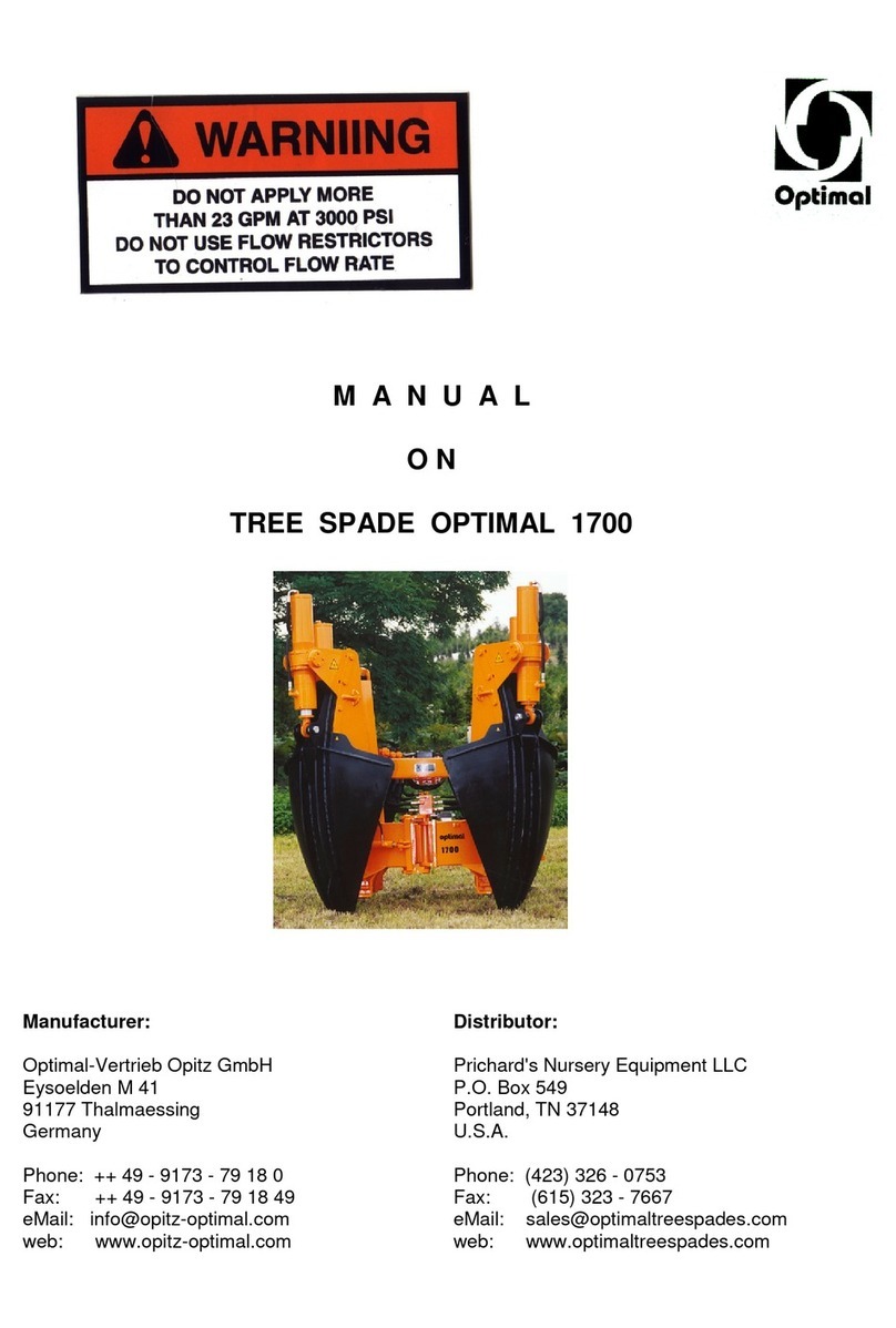
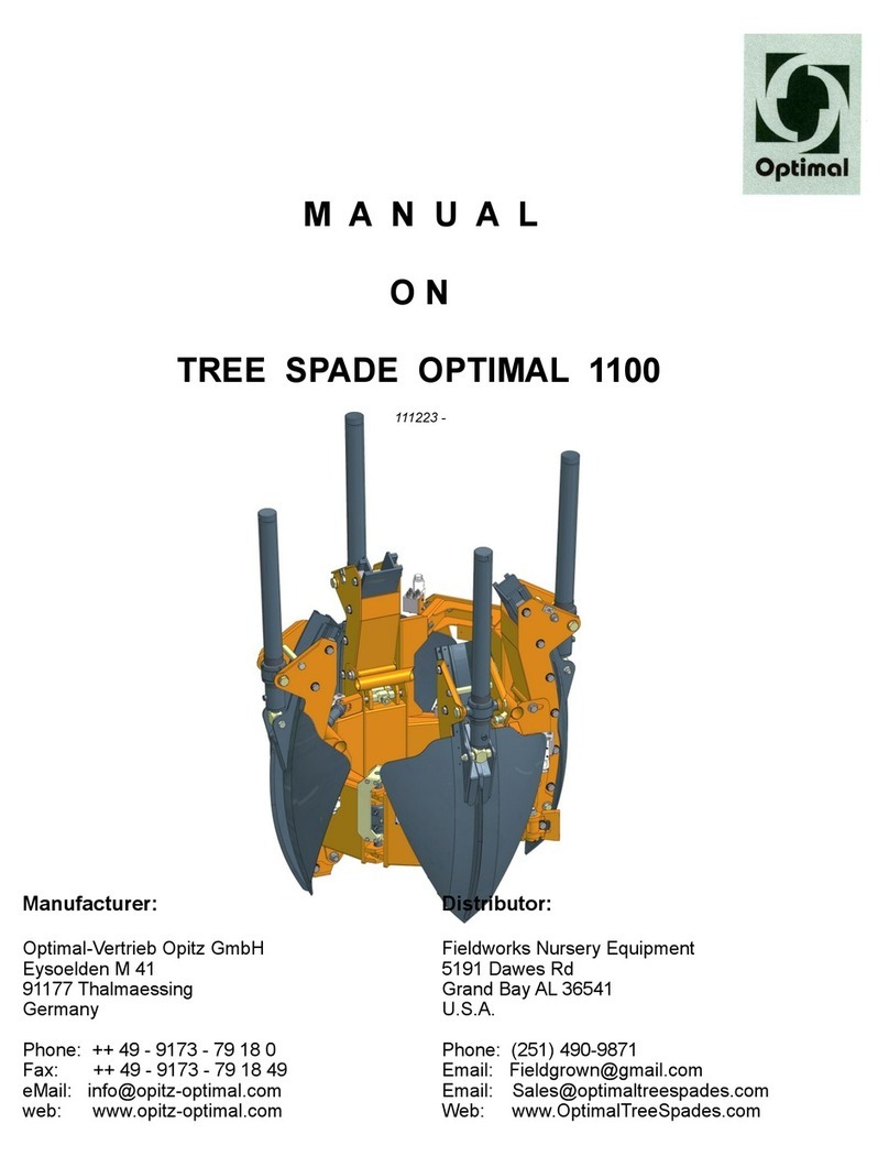
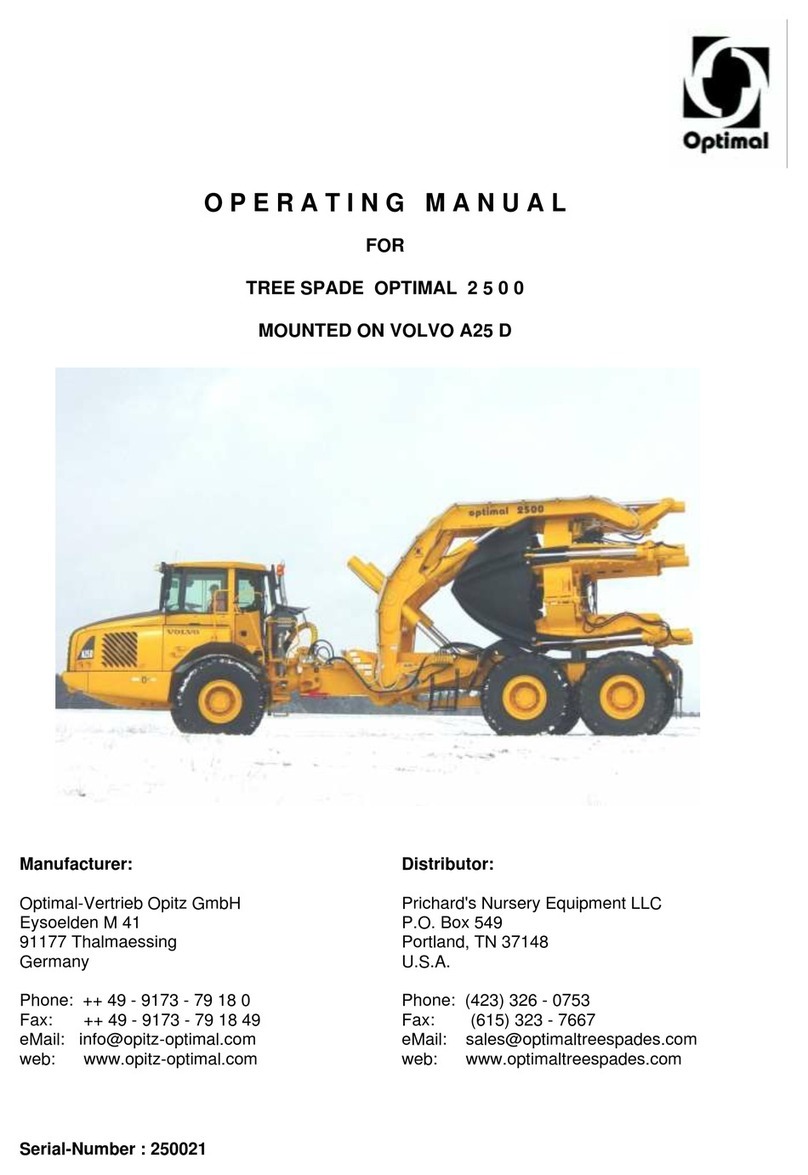
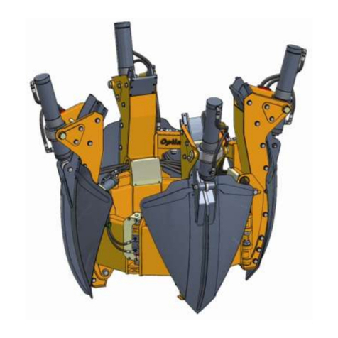
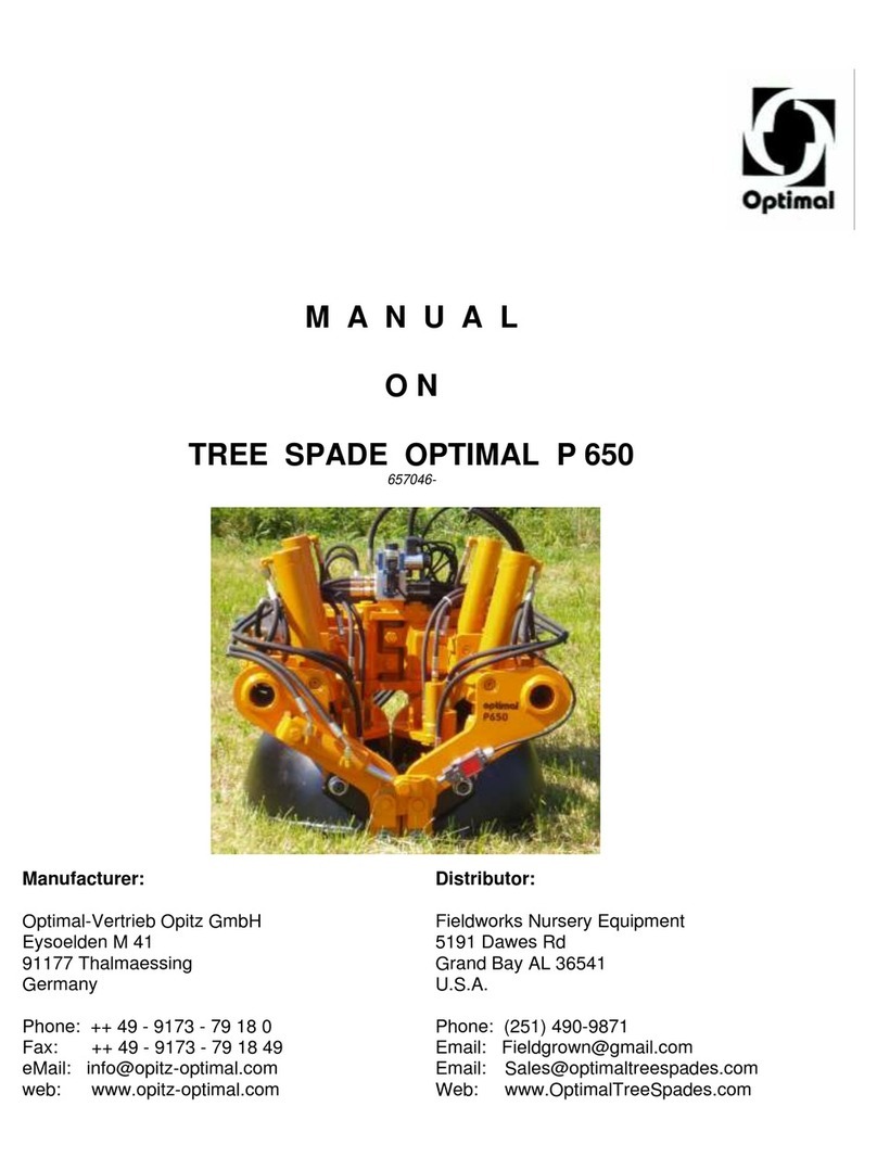
Optimal 30.25 User manual

M A N U A L
O N
TREE SPADE OPTIMAL 30.25
3025003 -
Manufacturer: Distributor:
Optimal-Vertrieb Opitz GmbH Prichard’s Nursery Equipment LLC
Eysoelden M 41 P.O.Box 549
91177 Thalmaessing Portland, TN 37148
Germany U.S.A.
Phone: ++ 49 –9173 –79 18 0 Phone: (423) 326 - 0753
Fax: ++ 49 –9173 –79 18 49 Fax: (615) 323 - 7667
web: www.opitz-optimal.com web: www.optimaltreespades.com

- 2 -
C O N T E N T S
Page
Safety Warnings 3
1. Operating Specifications 5
2. Assembly 6
3. Putting into Service 7
4. Operating Instructions 8 - 10
5. Care and Maintenance 11 - 14
6. Appendix
6.1 Attachment Points 15
6.2 Wiring diagram for Control Box 16
6.3 Wiring Diagram for Control System 17
6.4 Wiring Diagram for Joystick (optional) 18
6.5 Hydraulic systems 19
6.6 Lubrication chart 20
7. Trouble Shooting 21 - 22
8. Warranty 23
9. Spare Parts List with Drawings 24 -
table 1 basic machine
table 2 blades
table 3 spade cylinder
table 4 gate cylinder
table 5 hydraulic system
table 6 electric controls

- 3 -
WARNING Operator must have read and understood instructions
before running the tree spade.
Untrained operators can cause injury or death.
Safety Alert Symbol: This symbol is used for important safety messages.
When you see this symbol, follow the message to
avoid personal injury or death.
Never use tree spade without instructions. See machine signs (decals), and Operation & Maintenance
Manual of tree spade. The operation instructions for power unit must be followed.
Before starting operations, bolts and hydraulic fittings must be checked to make sure they are free of damage
and well tightened. Defective or loose hose pipes might cause serious injuries and therefore must be
replaced immediately.
The operator is responsible for ensuring that no person is near the tree spade when in operation.
No one should be underneath the raised tree spade or near shearing and pinching areas, or near any
hydraulic components. We are advising the user that due to their functional positions and movements the
danger areas cannot be furnished with protective guards.
Keep bystanders well away from work area.
Do not perform any manual work on the tree or shrub when it is inside the tree spade. In particular, do not
check the position of the tree or shrub by hand or feet when it is inside the tree spade. Do not tie the tree or
shrub when it is near or inside the machine.
When sight is limited, an assistant should direct the operator by hand signals.
When driving, the tree spade should be in the lowest possible position.
When moving and working on public roads, the traffic rules and regulations must be adhered to.
Never leave power unit with engine running or with lift arms up.
To park, engage parking brake and put tree spade flat on the ground.
When doing cleaning, maintenance or repair work, lower the tree spade to the ground
and stop the engine of the power unit.
Never modify equipment. Use only original spare parts approved by manufacturer for
this particular model tree spade.
When digging, it might happen that a stone gets caught between two blades and the blades get bent. This
causes tremendous tension in the steel blade. Do not try to release the stone by means of a crow bar or
other tools. Place the digging head again into the planting hole and retract the blades. Thereby the stone will
come loose and the blades which got a high degree of bending strength will regain their former shape. After
that the root ball can be dug again.
The operator must be sure that the ground he is going to dig is free from any underground installations such
as cables, pipes or any other utilities or dangerous matter. Damaging such underground installations or
matter is dangerous and might result in serious injury or death.
Safety stickers have been placed on the tree spade to warn the user of possible dangers. In case a safety
sticker has been worn or destroyed, it must be replaced immediately.
Safety stickers can be ordered with your distributor or the manufacturer. For ordering please use the part
numbers listed on page 2A. Fix the stickers on the locations marked on page 2A.

- 4 -
2. 1. 6. 3.
Part N° 7118000008
Part N° 7118000008 Part N° 7118000009
8. Part N° 7118000029
Part N° 7118000068
Part N° 7118000015 Part N° 7118000006 Part N° 7118000004 Part N° 7118000010 Part N° 7118000016
Part N° 7118000017 Part N° 7118000013
5.
Part N° 7118000007
4. 7.
Part N° 7118000012 Part N° 7118000014
Part N° 7118000020
Part N° 7118000014 Part N° 7118000014

- 5 -
1. Operating Specifications
Description Tree Spade OPTIMAL 30.25
serial number 3025 …
capacity upper root ball diameter 78 cm (31")
root ball depth 66 cm (26")
dimensions of height 135 cm (53")
basic machine width, frame closed 216 cm (85")
width, frame open 226 cm (89")
clearance between open gate 117 cm (46")
weight basic machine, empty 790 kg (1742 lbs.)
rated type of attachment attachment by means of back plate
to loader or excavator
minimum lift capacity 1350 kg (2970 lbs.)
the power unit must be equipped with
an auxiliary double-acting hydraulic
circuit for implements:
working pressure 160 - 200 bar (2300-2900 lbs/in²)
oil flow rate 40 - 60 l/min. (11 - 16 GPM)
controls electro-hydraulic valves, double-acting,
individual spade control;
actuation by electric control box;
max. power input 10 Ampere
field of application tree nurseries; gardens; civic greens

- 6 -
2. Assembly
IMPORTANT: When doing assembly work, heed relevant
instructions of manufacturers of power unit!
2.1 Back Plate
The tree spade is attached to the power unit by means of a back plate.
The back plate is procured from the manufacturer of the power unit,
or it might be fabricated according to the drawings and instructions of
the manufacturer of the power unit.
The back plate is to be furnished with borings as per drawing page 16.
At these attachment points the tree spade is bolted tightly to the back plate.
2.2 Installation of Electro-Hydraulic Control (wiring diagram page 16/17/18)
2.2.1 Install control box at suitable place in the cabin, e.g. at dashboard
2.2.2 Install 13-pole socket next to the push-on connector for the implement hydraulics.
A mounting bracket has been provided.
2.2.3 Run 12-pole cable from control box to 13-pole socket.
2.2.4 The control box must be connected to the power supply (12V) of the power unit.
Important: Electric power should be flowing only when the ignition of the power
unit is activated, otherwise the battery may run down.
Maximum power input 10 Ampere !
Now the tree spade is ready for operation.

- 7 -
3. Putting into Service
The tree spade with the back plate is attached and secured to the power unit.
Both the hydraulic connecting hoses of the tree spade are to be connected
to the hydraulic disconnect of the auxiliary hydraulic circuit of the power unit.
The plug of the electric control cable is to be plugged into the socket on
the power unit (see section 2.2.2).
Make sure that hydraulic working pressure and oil flow of power unit meets
the requirements as laid down in the operating specifications on page 5.
IMPORTANT: The hydraulic disconnect of the tree spade and
the power unit must match and must be connected
properly. Faulty connections are extremely dangerous.
After the first working day, the screws of the tension blocks must be
checkedand re-tightened, if necessary.
When operating the power unit, follow the
instructions of the operating manual of the
power unit !

- 8 -
4. Operating Instructions
IMPORTANT: The Operator must be a reliable person. Before commencing
production work, he or she must study these operating instructions
thoroughly.
The following safety instructions must be observed:
It is the operator's prime duty to ensure that any persons must stay
clear off the danger area. Special care must be taken that no one is
ever under the raised tree spade, or near the potential shearing
and pinching areas, or near the opened gate, near the spades or
near any hydraulic components.
Do not perform any manual work at the tree or shrub when it is
inside the tree spade. In particular, do not check the position of the
tree or shrub by hand or feet when it is inside the tree spade. Do
not bind the tree or shrub when it is near or inside the machine.
When sight is limited, an assistant should direct the operator by
hand signals.
Before starting to work with the tree spade, make sure the
hydraulic fittings and the bolts are properly tightened and are free
from any defects.
4.1 Control Box
The work movements are controlled as follows:
Pre-Selector Manual Controls
(hydraulic)
0 : control box switched off
(LED light indicates when gate is not locked)
function 1 : ---
function 2 : gate open / close
function 3 : blades up / down
function 4 : stabilizers (optional) up / down
The control box is installed in the driver's cabin. The function required
is preset with the pre-selector of the control box, and it is then
activated by means of the manual control lever or pedal respectively.
The tree spade is equipped with individual blade control as standard,
i.e. each blade can be controlled individually with toggle switches S2;
S3 and S4.
Individual blade control is of particular advantage when soil conditions Pre-Selector
are difficult.

- 9 -
4.2 Operation
4.2.1 Lower the tree spade with the lift arms of the power unit until the blade points are about
20 cm (8") above the ground.
4.2.2 Now the gate has to be opened:
pre-selector: function 2, gate
manual control: open
4.2.3 With the gate wide open, the tree spade is driven towards the tree to be dug. Position the
tree into the centre of the circular frame of the tree spade, then close the gate:
pre-selector: function 2, gate
manual control: close
4.2.4 Now, the tree spade is lowered to the ground and brought into a level position by means
of the lift arms of the power unit.
Again check if the tree is positioned in the centre of the frame, and correct, if necessary.
4.2.4 In case the power unit had been furnished with rear stabilizers of its own, extend rear
stabilizers with the respective control valve of the power unit.
But in case stabilizers have been installed with the tree spade and they are controlled by
Optimal control box, extend rear stabilizers by setting
pre-selector: function 4 (optional), rear stabilizers
manual control: down
4.2.5 Now proceed with digging:
pre-selector: function 3, blades (S2-S4)
manual control: down
The blades are pressed into the soil by means of spade cylinders suspended at the
spade towers. When all three blades are activated simultaneously, only the blades which
encounter the least soil resistance are moving at a given time.
In the event the tree spade lifts from the ground, retract the blades slightly (manual
control: "up") and then dig again, or press the blades down one by one, or by opposite
pairs. In either case, the digging movements must be carried out step by step, until all
blades are completely pressed into the soil. When digging, do not rock the tree spade
forward and backward by means of the tilting cylinder of the power unit!

- 10 -
4.2.6 Once all blades have been completely pressed into the soil, the tree spade with the
planting material is lifted out of the ground by means of the lift arms of the power unit.
4.2.7 The root ball is lowered by means of the lift arms of the power unit.
4.2.8 The rear stabilizers are retracted with the control valve of the loader, or with the optional
function 4 (up) of the pre-selector.
4.2.9 When work has been accomplished, the pre-selector is set to 0.
IMPORTANT:When moving and working on public roads, the traffic rules
and regulations must be adhered to.
When driving, the tree spade should be in the lowest possible
position.
When digging, it might happen that a stone gets caught between
two blades and the blades get bent. This causes tremendous
tension in the steel blade. Do not try to release the stone by means
of a crow bar or other tools.
Place the digging head again into the planting hole and retract the
blades. Thereby the stone will come loose and the blades which
got a high degree of bending strength will regain their former
shape. After that the root ball can be dug again.
4.3 Releasing the Tree
When transplanting, or when placing the tree in a basket, lower the tree spade by means
of the lift arms, retract spades (function 3 “blades” , control valve “up”) and open gate
(function 2 "gate", control valve "open").
When the work has been finished, set the pre-selector in off-position (function 0).
If the tree spade is controlled by means of a joy stick, the hydraulics are off when no
button is being pressed.

- 11 -
5. Care and Maintenance
IMPORTANT: Tree spade must be lowered to the ground and switched off when
doing cleaning, maintenance or repair work !
Use original spare parts only !
The tree Spade must be inspected by an expert on
operational safety once per year !
Do not alter the design of the tree spade without having
consulted the manufacturer !
Check screws regularly on tight fit. Tighten firmly, if necessary !
5.1 Blade Guides
Thanks to the plastic lining the spade guides do not require special care.
Once the plastic lining has been worn, to the point were the heads of the countersunk
screws are even with the surface of the plastic linings, they must be replaced to prevent
the screws from damaging the blades.
IMPORTANT: Keep the guides cleaned.
5.2 Lubrication
Once per week lubricate all greasing points with lithium-based grease,
as per lubrication chart, Page 20
5.3 Hydraulic Oil Supply
Check level of hydraulic oil regularly. For checking, retract all blades “up”
and lower the tree spade to the ground. If in that position the oil level is
below the mark of the sight glass, oil must be refilled.
5.4 Hydraulic Hoses
All hydraulic hoses must be inspected at least once per year. Damaged hoses
must be replaced. At least after 6 years all hoses must be replaced.
5.5 Cylinders
In case the tree spade is not getting used for two weeks, all piston rods of the hydraulic
cylinders must be cleaned and covered with a preserving oil film.

- 12 -
5.6 Adjusting Blades
Loosen locking screws A and counter nuts B at
both sides.
Adjust blade with nuts C (M16).
When blade is in proper position, tighten locking
screws A and counter nuts B.
In case the blades cannot be adjusted to the required
position, check blade guides and plastic linings. Replace
them, if necessary.
In case guides and linings are in good condition, the tip of
the blades might be bent and must be reshaped.
Important: The blades must be bent in cold condition by
means of a hydraulic press.
The Blades must never be heated!!!

- 13 -
5.7 Replacing Plastic Bushings at Gate Cylinder
Illustration 6
Illustration 7
Illustration 8
Illustration 6: Overall view of gate cylinder in position.
Illustration 7: Loosen nut M16 (E) and remove shoulder bolt M16 (D). If necessary, remove
hydraulic hoses, too.
Illustration 8: Remove plastic bushings (F) with suitable object and insert new bushings.
Then reassemble gate cylinder, shoulder bolt, nut and, if applicable, hydraulic
hoses.
D
F
F
D
E
E

- 14 -
5.8 Replacing Plastic Lining and Sliding Disk at Blade Guides
Put the blade in to the lowest position
remove screws M8 (G) and draw blade
(H) down until free.
replace worn plastic linings and screws
by new.
In case that the sliding disks are also
worn, they must be replaced by new
ones.
Use only new original parts.
installation is done in the reverse order.
Tightening torque:
-screws (G) to fasten blade (M8x20): 42 Nm
H
G
K
J
J

- 15 -
6.1 Attachment points

- 16 -
6.2 Wiring Diagram for Control Box

- 17 -
6.3 Wiring Diagram for Control System

- 18 -
6.4 Wiring Diagram for Joystick (optional)

- 19 -
6.5 Hydraulic system

- 20 -
6.6 lubriction chart
-- lubricate once per week
Table of contents
Other Optimal Lawn And Garden Equipment manuals
Popular Lawn And Garden Equipment manuals by other brands

P3 International
P3 International Attack Wave Pestrepeller P7816 Specifications

Billy Goat
Billy Goat SV50 Operator owner's manual

Agri-Fab
Agri-Fab 45-01762 quick start guide

Rentokil
Rentokil Lumnia Slim instruction manual

Weed Eater
Weed Eater LT 20V owner's manual

Toro
Toro Lynx SmartHub Installation and user guide

Mosquito Magnet
Mosquito Magnet Liberty Operation and assembly instructions

Levita
Levita S 1400 operating instructions

Cardigo
Cardigo 62450 instruction manual

Scag Power Equipment
Scag Power Equipment 37621219, 37621220 Operator's manual

Sears
Sears Craftsman 316.794450 Operator's manual

Simplicity
Simplicity 4565 Illustrated parts list