Optimal 1700 User manual

M A N U A L
O N
TREE SPADE OPTIMAL 1700
Manufacturer: Distributor:
Optimal-Vertrieb Opitz GmbH Prichard's Nursery Equipment LLC
Eysoelden M 41 P.O. Box 549
91177 Thalmaessing Portland, TN 37148
Germany U.S.A.
Phone: ++ 49 - 9173 - 79 18 0 Phone: (423) 326 - 0753
Fax: ++ 49 - 9173 - 79 18 49 Fax: (615) 323 - 7667
eMail: info@opitz-optimal.com eMail: sales@optimaltreespades.com
web: www.opitz-optimal.com web: www.optimaltreespades.com

- 1 -
C O N T E N T S
Page
Safety Warnings 2
1. Operating Specifications 3
2. Assembly 4
3. Putting into Service 5
4. Operating Instructions 6 - 8
5. Care and Maintenance 9 - 10
6. Appendix
6.1 Attachment Points 11
6.2 Installation of electro-hydraulic controls 12 - 15
6.3. Lubrication Chart 16
7. Spare Parts List with Drawings 15 - 34
8. Trouble Shooting 35 -37
9. Warranty 38

- 2 -
WARNING Operator must have read and understood instructions
before running the tree spade.
Untrained operators can cause injury or death.
Safety Alert Symbol: This symbol is used for important safety messages.
When you see this symbol, follow the message to
avoid personal injury or death.
Never use tree spade without instructions. See machine signs (decals), and Operation & Maintenance
Manual of tree spade. The operation instructions for power unit must be followed.
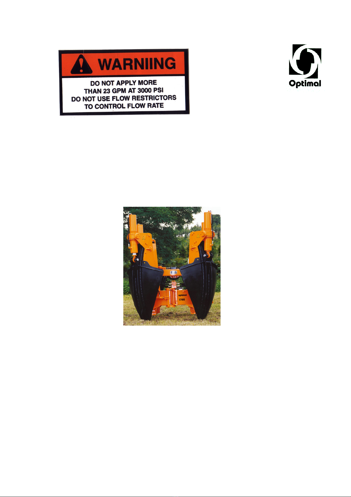
Before starting operations, bolts and hydraulic fittings must be checked to make sure they are free of damage
and well tightened. Defective or loose hose pipes might cause serious injuries and therefore must be
replaced immediately.
The operator is responsible for ensuring that no person is near the tree spade when in operation.
No one should be underneath the raised tree spade or near shearing and pinching areas, or near any
hydraulic components. We are advising the user that due to their functional positions and movements the
danger areas cannot be furnished with protective guards.
Keep bystanders well away from work area.
Do not perform any manual work on the tree or shrub when it is inside the tree spade. In particular, do not
check the position of the tree or shrub by hand or feet when it is inside the tree spade. Do not tie the tree or
shrub when it is near or inside the machine.
When sight is limited, an assistant should direct the operator by hand signals.
When driving, the tree spade should be in the lowest possible position.
When moving and working on public roads, the traffic rules and regulations must be adhered to.
Never leave power unit with engine running or with lift arms up.
To park, engage parking brake and put tree spade flat on the ground.
When doing cleaning, maintenance or repair work, lower the tree spade to the ground
and stop the engine of the power unit.
Never modify equipment. Use only original spare parts approved by manufacturer for
this particular model tree spade.
When digging, it might happen that a stone gets caught between two blades and the blades get bent. This
causes tremendous tension in the steel blade. Do not try to release the stone by means of a crow bar or
other tools. Place the digging head again into the planting hole and retract the blades. Thereby the stone will
come loose and the blades which got a high degree of bending strength will regain their former shape. After
that the root ball can be dug again.
The operator must be sure that the ground he is going to dig is free from any underground installations such
as cables, pipes or any other utilities or dangerous matter. Damaging such underground installations or
matter is dangerous and might result in serious injury or death.
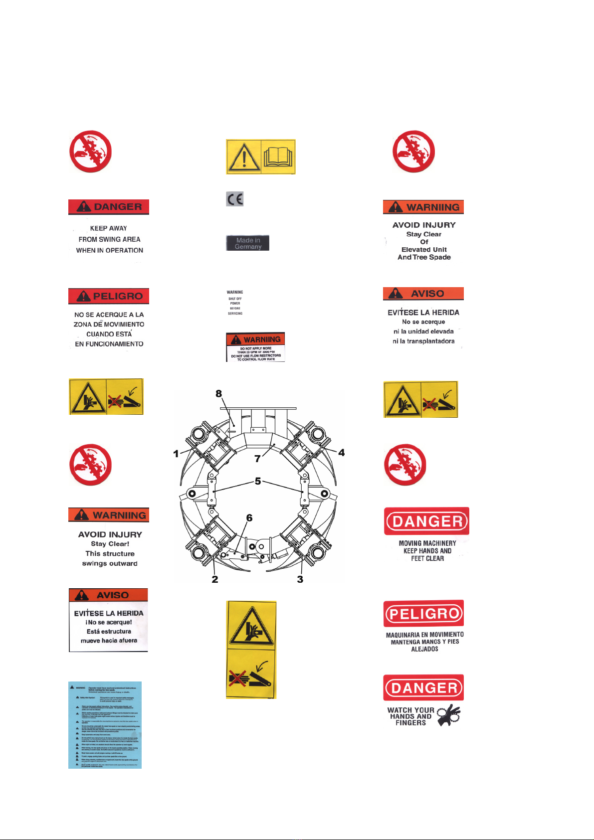
Safety stickers have been placed on the tree spade to warn the user of possible dangers. In case a safety
sticker has been worn or destroyed, it must be replaced immediately.
Safety stickers can be ordered with your distributor or the manufacturer. For ordering please use the part
numbers listed on page 2A. Fix the stickers on the locations marked on page 2A.

- 2A -
1. Tower: 4. Tower:
7. Frame:
Part N°7118000001 Part N°7118000004 Part N°7118000001
Part N°7118000005
Part N°7118000006
Part N°7118000008
8. Oil - Manifold:
Part N°7118000009
Part N°7118000010
Part N°7118000015 Part N°7118000016
5. Gate Cylinder:
Part N°7118000011
5. Gate Cylinder:
Part N°7118000007 Part N°7118000007
2. Tower: 3. Tower:
Part N°7118000001 Part N°7118000001
Part N°7118000012 Part N°7118000014
6. Lock Cylinder:
Part N°7118000020 Part N°7118000017
Part N°7118000019
Part N°7118000018 Part N°7118000013

- 3 -
1. Operating Specifications
Description Tree Spade OPTIMAL 1700
serial number 170
capacity upper root ball diameter 165 cm (65")
root ball depth 100 cm (39")
dimensions of height 208 cm (82")
basic machine width, frame closed 180 cm (71")
width, frame open 270 cm (106")
clearance between open gate 110 cm (43")
weight basic machine, empty 2220 kg (4840 lbs.)
rated type of attachment attachment by means of back plate
to loader or excavator
minimum lift capacity 6000 kg (13200 lbs.)
the power unit must be equipped with
an auxiliary double-acting hydraulic
circuit for implements:
working pressure 160 - 200 bar (2300-2900 lbs/in²)
oil flow 60 l/min. (16 GPM)
controls electro-hydraulic valves, double-acting,
for three or four functions
actuated by joy stick
field of application tree nurseries; gardens; civic greens

- 4 -
2. Assembly
IMPORTANT: When doing assembly work, heed relevant
instructions of manufacturers of power unit!
2.1 Back Plate
The tree spade is attached to the power unit by means of a back plate.
The back plate is procured from the manufacturer of the power unit,
or it might be fabricated according to the drawings and instructions of
the manufacturer of the power unit.
The back plate is to be furnished with borings as per drawing page 11.
At these attachment points the tree spade is bolted tightly to the back plate.
2.2 Installation of Electro-Hydraulic Control
2.2.1 Install rotary joy stick at suitable and dry location in the power unit,
e.g. at the hydraulic lever.
2.2.2 Install 13-pole electric socket next to hydraulic disconnect of auxiliary hydraulic circuit at
the power unit.
2.2.3 The blue wire should be connected to 12 VDC, the brown wire to the ground.
It is best if the blue wire is connected to a power source that is only available when the
ignition switch is on, to avoid inadvertently leaving power on the tree spade.

- 5 -
3. Putting into Service
The tree spade with the back plate is attached and secured to the power unit.
Both the hydraulic connecting hoses of the tree spade are to be connected
to the hydraulic disconnect of the auxiliary hydraulic circuit of the power unit.
The plug of the electric control cable is to be plugged into the socket on
the power unit (see section 2.2.2).
Make sure that hydraulic working pressure and oil flow of power unit meets
the requirements as laid down in the operating specifications on page 3.
IMPORTANT: The hydraulic disconnect of the tree spade and
the power unit must match and must be connected
properly. Faulty connections are extremely dangerous.
If the back-flow of the hydraulic oil is impeded, a pressure relief will divert the
excess oil into an overflow tank. Possible reasons could be ill-matching disconnects
or an excessive oil flow. In that case the oil flow must be reduced as per instruction of the
manufacturer of the power unit.
After the first working day, the screws of the tension blocks must be checked
and re-tightened, if necessary.
IMPORTANT: When operating the power unit, follow the
instructions of the operating manual of the
power unit !

- 6 -
4. Operating Instructions
IMPORTANT: The Operator must be a reliable person. Before commencing
production work, he or she must study these operating instructions
thoroughly.
The following safety instructions must be observed:
It is the operator's prime duty to ensure that any persons must stay
clear off the danger area. Special care must be taken that no one is
ever under the raised tree spade, or near the potential shearing
and pinching areas, or near the opened gate, near the spades or
near any hydraulic components.
Do not perform any manual work at the tree or shrub when it is
inside the tree spade. In particular, do not check the position of the
tree or shrub by hand or feet when it is inside the tree spade. Do
not bind the tree or shrub when it is near or inside the machine.
When sight is limited, an assistant should direct the operator by
hand signals.
Before starting to work with the tree spade, make sure the
hydraulic fittings and the bolts are properly tightened and are free
from any defects.
4.1 The Controls
The controls permit work with or without individual spade controls.
4.1.1. Working without individual spade controls:
Joystick Control Valve Work Movement (actuated
by Manual Lever or Pedal)
T3 gate lock unlock / lock
T5 gate open / close
T4 blades up / down
(T6 stabilizers up / down)

- 7 -
4.1.2 For working with individual spade controls, first press switch T2.
Control light H1 will illuminate, digging operation can commence.
Joystick Control Valve Work Movement (actuated
by Manual Lever or Pedal)
T3 blade 1 up / down
T4 blade 2 up / down
T5 blade 3 up / down
T6 blade 4 up / down
The function required is selected by pressing the Joystick button and then activated
by the manual control valve of the auxiliary hydraulic circuit of the power unit.
With some loaders this valve might be activated by a pedal.
4.2 Operation
4.2.1 First lower the tree spade with the lift arms of the power unit until the blade points are
about 20 cm (8") above the ground.
4.2.2 Preset button T3 "gate lock" with rotary switch and activate "unlock" with control valve.
Then preset button T5 "gate" and activate "open" with control valve.
4.2.3 With the gate open drive towards the tree. When the tree is positioned in the center of the
main frame, preset button T5 "gate" and activate "close".
Then preset button T3 "gate lock" and activate "lock".
Locking the frame before starting the digging operation is of utmost
importance and must never be omitted !
If the gate is not locked properly, the frame may be bent !
In order to prevent the spades from digging with the gate not being properly locked, the
gate lock is furnished with a safety switch. If the spades do not move although the
operator followed above instructions, this malfunction is probably caused by a branch or
some other object obstructing the movement of the gate lock latch. Remove the
obstruction and try again.
Do not slacken the socket head screw on the mounting plate
or alter the position of the safety switch.
After having locked the gate, lower the tree spade to the ground and get it into level
position. Again check if the tree is positioned in the center of the frame and correct, if
necessary.
4.2.4 If the power unit is furnished with rear stabilizers, extend stabilizers prior to digging (T6).

- 8 -
4.2.5 Now digging can commence.
For basic operation, press button T4 "blades" and activate "down" with control valve.
Now the spade cylinders force the blades into the ground.
Because all 4 spade cylinders are activated by one valve at the same time, the blades
which encounter the least resistance at any given time will penetrate into the soil first.
If, however, you prefer digging with individual spade control, press button T2 and choose
your spade as described in section 4.1.2.
When the frame begins to lift when digging, retract blades and then continue digging.
Do not rock the tree spade forward and backward with the tilting cylinder of the power
unit when the blades are in the ground!
Once all blades have been completely pressed into the soil, the tree spade with
the planting material is lifted out of the ground by means of the lift arms of
the power unit.
Before travelling, rear stabilizers must be retracted !
IMPORTANT: When moving and working on public roads, the traffic rules
and regulations must be adhered to.
When driving, the tree spade should be in the lowest possible
position.
4.3 Releasing the Tree
When transplanting, or when placing the tree in a basket, lower the tree spade by means
of the lift arms, retract spades (button T4 “blades” , control valve “up”) then unlock gate
(button T3 "gate lock", control valve "unlock") and open gate (button T5 "gate", control
valve "open").
IMPORTANT: When digging, it might happen that a stone gets caught between
two blades and the blades get bent. This causes tremendous
tension in the steel blade. Do not try to release the stone by means
of a crow bar or other tools. Place the digging head again into the
planting hole and retract the blades. Thereby the stone will come
loose and the blades which got a high degree of bending strength
will regain their former shape.
After that the root ball can dug again.

- 9 -
5. Care and Maintenance
5.1 Blade Guides
Thanks to the plastic lining the spade guides do not require lubrication.
Once the plastic lining has been worn to the point were the heads of the countersunk
screws are even with the surface of the plastic linings, they must be replaced to prevent
the screws from damaging the blades.
IMPORTANT: After the first digging day the screws (Item 4, page 18) of the
tension block have to be tightened with a torque of 420 Nm
(ft.lb.310).
Make sure tension bolts at bottom of guides are always tight !
Keep the guides cleaned.
5.2 Lubrication
Once per week lubricate all greasing points with lithium-based grease,
as per lubrication chart, Page 16
5.3 Hydraulic Oil Supply
Check level of hydraulic oil regularly. For checking, retract all blades “up”
and lower the tree spade to the ground. If in that position the oil level is
below the mark of the sight glass, oil must be refilled.
5.4 Hydraulic Hoses
All hydraulic hoses must be inspected at least once per year. Damaged hoses
must be replaced. At least after 6 years all hoses must be replaced.
5.5 Cylinders
In case the tree spade is not getting used for two weeks, all piston rods of the hydraulic
cylinders must be cleaned and covered with a preserving oil film.

- 10 -
IMPORTANT: Tree spade must be lowered to the ground and switched
off when doing cleaning, maintenance or repair work !
Use original spare parts only !
The tree Spade must be inspected by an expert on
operational safety once per year !
Do not alter the design of the tree spade without having
consulted the manufacturer !

- 11 -
OPTIMAL-Vertrieb Opitz GmbH
Eysölden M 41
D-91177 Thalmässing
OPTIMAL 1700
ATTACHMENT POINTS

- 12 -
OPTIMAL-Vertrieb Opitz GmbH
Eysölden M 41
D-91177 Thalmässing
OPTIMAL 1700
ELECTRO – HYDRAULIC CONTROLS

- 13 -
OPTIMAL-Vertrieb Opitz GmbH
Eysölden M 41
D-91177 Thalmässing
OPTIMAL 1700
CONNECTION OF CIRCUIT BOARD

- 14 -
OPTIMAL-Vertrieb Opitz GmbH
Eysölden M 41
D-91177 Thalmässing
OPTIMAL 1700
CONNECTING PLAN FOR THE 13-
POLE
COUPLING

- 15 -
OPTIMAL-Vertrieb Opitz GmbH
Eysölden M 41
D-91177 Thalmässing
OPTIMAL 1700
CONNECTING PLAN FOR TERMINAL BOX

- 16 -
OPTIMAL-Vertrieb Opitz GmbH
Eysölden M 41
D-91177 Thalmässing
OPTIMAL 1700
LUBRICATION CHART

S P A R E P A R T S
O N
TREE SPADE OPTIMAL 1700
Manufacturer: Distributor:
Optimal-Vertrieb Opitz GmbH Prichard’s Nursery Equipment LLC
Eysoelden M 41 P.O.Box 250
91177 Thalmaessing Harrison, TN 37341-0250
Germany U.S.A.
Phone: ++ 49 – 9173 – 79 18 0 Phone: (423) 326 - 0753
Fax: ++ 49 – 9173 – 79 18 49 Fax: (423) 344 - 7064
eMail: info@opitz-optimal.com eMail: sales@optimaltreespades.com
web: www.opitz-optimal.com web: www.optimaltreespades.com

- 18 -
Other manuals for 1700
1
Table of contents
Other Optimal Lawn And Garden Equipment manuals