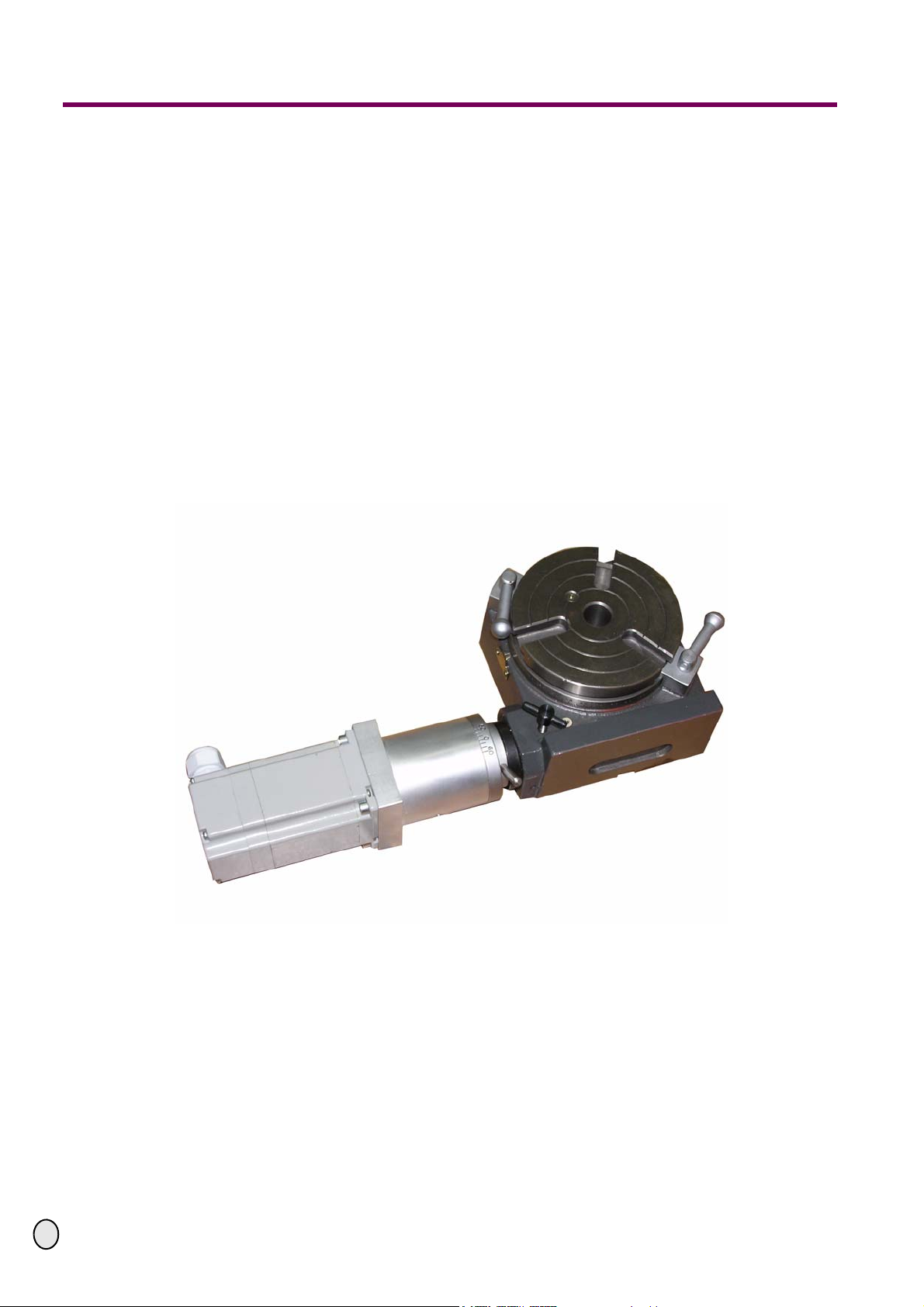
Optimum RT 100 CN User manual
OPTIMUM
MASCHINEN - GERMANY
25.8.09 Page 1Adapter kit RT 100 /150 CNC ; Version 1.1.1
© 2009
GB
Conversion instruction
Version 1.1.1
Adapter kit
RT 100/ 150 CNC
Keep for future reference!
Illustr. 0-1: RT100

OPTIMUM
MASCHINEN - GERMANY
25.8.09Page 2 Adapter kit RT 100 /150 CNC ; Version 1.1.1
© 2009 GB
Contents
1 Safety warnings (warning notes)
1.1 Classification of hazards......................................................................................................... 3
1.2 Proper use .............................................................................................................................. 4
1.3 Required auxiliary material...................................................................................................... 4
2 Packing list RT 100 CNC
3 Packing list RT 150 CNC
4 Assembly RT 100/ 150 CNC
4.1 Assembly on the RT................................................................................................................ 7
5 Installation of the step motors
5.1 Wiring.................................................................................................................................... 11
6 RT CNC
7 Appendix
7.1 Copyright............................................................................................................................... 16
7.2 Terminology/Glossary........................................................................................................... 16
7.3 Liability claims for defects / warranty .................................................................................... 17
7.4 Note regarding disposal / options to reuse:........................................................................... 17
7.5 Disposal ................................................................................................................................ 19
7.6 RoHS , 2002/95/CE............................................................................................................... 19
7.7 Product follow-up .................................................................................................................. 20
OPTIMUM
MASCHINEN - GERMANY
Safety warnings (warning notes)
25.8.09 Page 3Safety warnings (warning notes) Adapter kit RT 100 /150 CNC ; Version 1.1.1
© 2009
GB
1 Safety warnings (warning notes)
1.1 Classification of hazards
We classify the safety warnings into various levels. The table below gives an overview of the
classification of symbols (pictograms) and warnings for the specific danger and its (possible)
consequences.
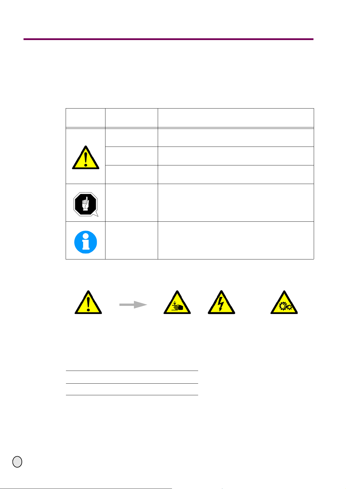
1.1.1 Glossary of symbols
Pictogram Alarm expres-
sion Definition/Consequences
DANGER! Imminent danger that will cause serious injury or death to
personnel.
WARNING! Risk: A danger that might cause serious injury or death to
personnel.
CAUTION! Danger of unsafe procedure that might cause injury to
personnel or damage to property.
ATTENTION!
Situation that could cause damage to the machine and
product and other types of damage.
No risk of injury to personnel.
INFORMATION
Application tips and other important or useful information
and notes.
No dangerous or harmful consequences for personnel or
objects.
In the case of specific dangers, we replace the pictogram by
or
General dan-
ger with a warning
of injuries to
hands, hazardous
electrical
voltage,
rotating parts.
gives additional advices
enumerations

Safety warnings (warning notes)
OPTIMUM
MASCHINEN - GERMANY
25.8.09Page 4 Safety warnings (warning notes) Adapter kit RT 100 /150 CNC ; Version 1.1.1
© 2009 GB
1.2 Proper use
WARNING!
In the event of improper use of the add-on pieces, it
• will endanger the user,
• will endanger the machine and other material property of the operator or user,
• may affect proper operation of the machine.
The attachment parts as conversion kit are provided for engine driven milling works of your
machine.
Improper
use! The milling machine with the adapter kit must only be placed and operated in dry and ventilated
rooms.
The handwheels on the driven axis need to be disassembled for safety reasons.
If the adapter kit is used in any way other than described above or modified without approval or
the company Optimum Maschinen Germany GmbH, the adapter kit is no longer properly used.
We do not take liability for any damage caused by improper use.
We would like to stress that any modifications to the construction, or technical or technological
modifications that have not been authorized by Optimum Maschinen GmbH will also render the
guarantee null and void.
1.3 Required auxiliary material
Means of shaft lock-down device "Loctite 648, join the shaft".
The designation of the parts in the assembly description corresponds to the numbering of the
packing list.
In order to degrease the shaft, a cleaner for brakes or a corresponding cleaning agent is
required.
Required tools:
Allen key

OPTIMUM
MASCHINEN - GERMANY
Packing list RT 100 CNC
25.8.09 Page 5Packing list RT 100 CNC Adapter kit RT 100 /150 CNC ; Version 1.1.1
© 2009
GB
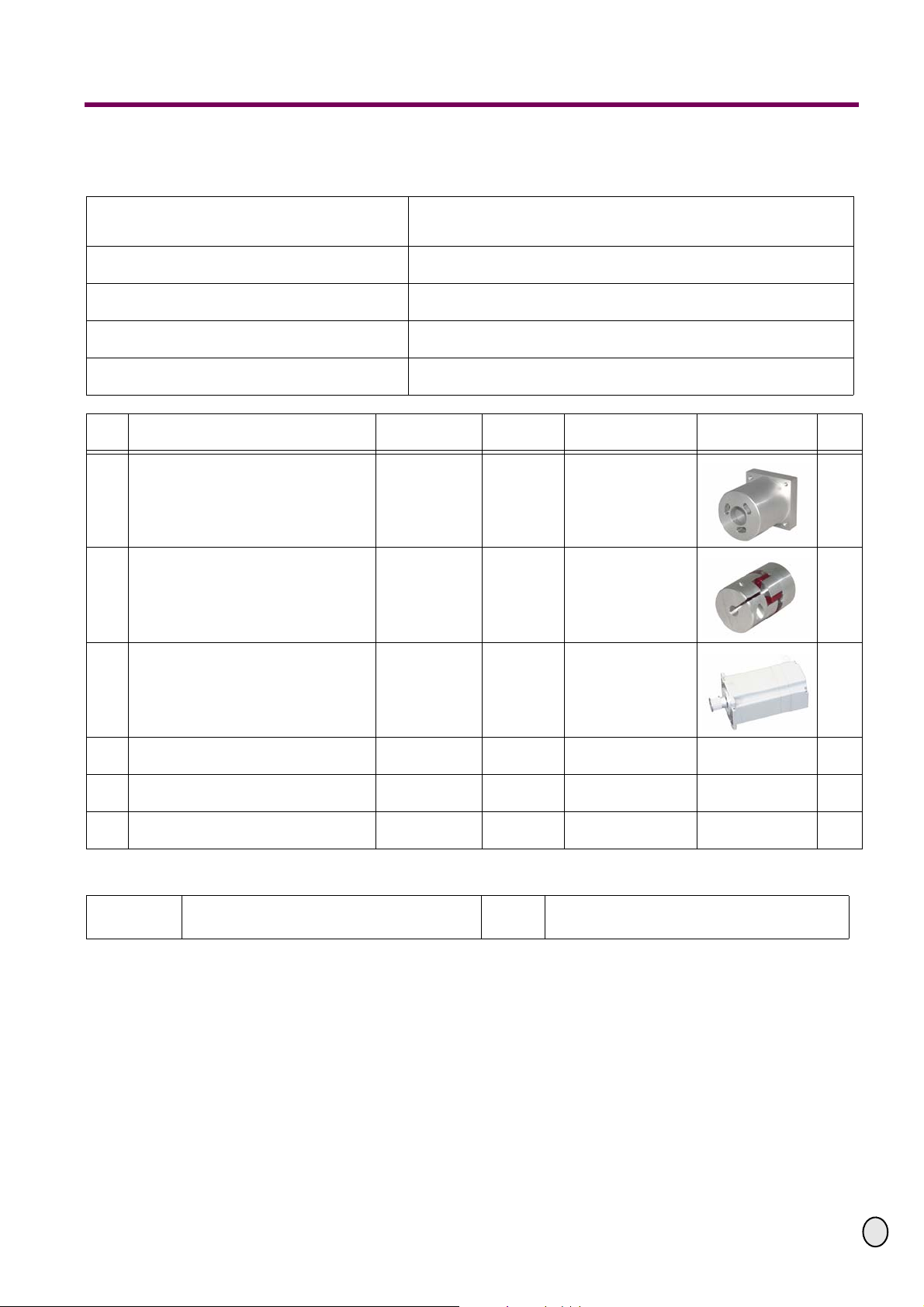
2 Packing list RT 100 CNC
Bezeichnung
Designation CNC - Adapter kit MK RT1 f
RT 100 CNC
Artikelnummer Anbausatz
Item No. assembly kit 3570510
Netto Gewicht
Net Weight 2 kg
Brutto Gewicht
Gross Weight 2.5 kg
Abmessung (Lx B x H)
Dimension (L x W x H) 320 x 285 x 80 mm
Nr.
No Bezeichnung
Description Artikelnummer
Article No. Teile Nr.
Part No. Grösse
Size Abbildung
Picture
Stck.
Qty.
1Gehäuse
Housing 0 357 0510 1 RT1CNC-01 1
2Kupplung
Clutch 0 357 0510 2 RT1CNC-02 1
3Schrittmotor
Step motor 357 3304 23H280-01EA
2,2 NM
3A 1
4Schraube
Screw DIN 4762 M5x15 4
5Schraube
Screw DIN 4762 M5x20 3
6Kabel
Cable wire -4 x 0,75mm23m
Prüfer:
Verified by: Datum:
Date:
Packing list RT 150 CNC
OPTIMUM
MASCHINEN - GERMANY
25.8.09Page 6 Packing list RT 150 CNC Adapter kit RT 100 /150 CNC ; Version 1.1.1
© 2009 GB
3 Packing list RT 150 CNC
Bezeichnung
Designation CNC - Adapter kit MK RT1 f
RT 150 CNC
Artikelnummer Anbausatz
Item No. assembly kit 3570510
Netto Gewicht
Net Weight 2 kg
Brutto Gewicht
Gross Weight 2.5 kg
Abmessung (Lx B x H)
Dimension (L x W x H) 320 x 285 x 80 mm
Nr.
No Bezeichnung
Description Artikelnummer
Article No. Teile Nr.
Part No. Grösse
Size Abbildung
Picture
Stck.
Qty.
1Gehäuse
Housing 0 357 0510 1 RT1CNC-01 1
2Kupplung
Clutch 0 357 0510 2 RT1CNC-02 1
3Schrittmotor
Step motor 357 3304 23H280-01EA
2,2 NM
3A 1
4Schraube
Screw DIN 4762 M5x15 4
5Schraube
Screw DIN 4762 M5x20 3
6Kabel
Cable wire -4 x 0,75mm23m
Prüfer:
Verified by: Datum:
Date:

OPTIMUM
MASCHINEN - GERMANY
Assembly RT 100/ 150 CNC
25.8.09 Page 7Assembly RT 100/ 150 CNC Adapter kit RT 100 /150 CNC ; Version 1.1.1
© 2009
GB
4 Assembly RT 100/ 150 CNC
4.1 Assembly on the RT
4.1.1 Unfasten and unscrew the hexagon
socket head screw of the handwheel
with an Allen key.
Illustr.4-1: Unscrew screws
4.1.2 Remove the handwheel from the shaft.
If you cannot pull it off easily, you can
detach the handwheel by slightly
knocking on it with a plastic tip hammer.
Illustr.4-2: Pull off handwheel
4.1.3 Take the feather key out of the shaft.
Illustr.4-3: Disassembly of feather key
Handwheel
Hexagon socket head
screw
Handwheel
Feather key

Assembly RT 100/ 150 CNC
OPTIMUM
MASCHINEN - GERMANY
25.8.09Page 8 Assembly RT 100/ 150 CNC Adapter kit RT 100 /150 CNC ; Version 1.1.1
© 2009 GB
4.1.4 Stick the housing on the RT, as shown.
Illustr.4-4: Mount housing
4.1.5 Fasten the housing with the three hexa-
gon socket head screws on the RT.
Please make sure that the housing is
screwed on in a way that the motor is
horizontally positioned on the RT.
Illustr.4-5: Fasten screws
4.1.6 Shift on half of the clutch with the lar-
ger holes on the shaft of the RT, as
shown.
Illustr.4-6: Fit clutch
Housing
RT
Housing
Hexagon socket head
screws
clutch

OPTIMUM
MASCHINEN - GERMANY
Assembly RT 100/ 150 CNC
25.8.09 Page 9Assembly RT 100/ 150 CNC Adapter kit RT 100 /150 CNC ; Version 1.1.1
© 2009
GB
4.1.7 Fasten the clutch through the holes of
the housing with an Allen key.
Illustr.4-7: Fasten clutch
4.1.8 Plug the other half of the clutch on the
shaft of the step motor.
Illustr.4-8: Clutch on the motor
4.1.9 The clutch should be pushed on the
shaft of the step motor as far as possi-
ble. Then fasten the clutch with an Allen
key.
Illustr.4-9: Fasten clutch
Holes of the housing
Clutch
Clutch
Step motor

Assembly RT 100/ 150 CNC
OPTIMUM
MASCHINEN - GERMANY
25.8.09Page 10 Assembly RT 100/ 150 CNC Adapter kit RT 100 /150 CNC ; Version 1.1.1
© 2009 GB
4.1.10 Align the clutch of the step motor in a
way that it fits with the counterpart in
the housing. Then put the motor on the
housing.
Illustr.4-10: Fit the step motor
4.1.11 Fasten the motor with the hexagon
socket head screws on the housing.
Illustr.4-11: Screw the motor
Step motor
Motor screw
This manual suits for next models
1
Table of contents


