Optimum ESI-100 IP-PBX User manual

ESI-100 IP-PBX
SIP Trunking using the
Optimum Business Sip
Trunk Adaptor and the
ESI-100 IP-PBX

ESI-100 IP-PBX
1. Overview 3
2. Prerequisites 3
3. ESI-100 Configuration 3
3.1 Network Settings 4
3.2 SIP Programming 5
3.3 Extensions/DID 7
3.4 Backup/Restore 9
2
Table of Contents

ESI-100 IP-PBX
1 Overview
The purpose of this configuration guide is to describe the steps needed to configure
the ESI-100 PBX for proper operation with Optimum Business Sip Trunking. The
steps below describe the basic configuration required to enable the PBX to use
Optimum Business SIP Trunking for inbound and outbound calling. Please refer to
the ESI-100 PBX documentation to configure advanced PBX features.
2 Prerequisites
Please follow the instructions in the Optimum Business SIP Trunk Set-up Guide. The
set-up guide was left by the Optimum Business technician at installation. If you do
not have the set-up guide, go to optimumbusiness.com/sip to download a copy.
The set-up guide describes the steps needed to configure the LAN side of the
Optimum Business SIP Trunk Adaptor (Edgewater 4552).
This configuration guide provides the configuration steps for both PBX registration
and Static IP or non-registration modes of PBX operation.
The PBX used in the lab comprises of the following:
Table 1 – PBX Information
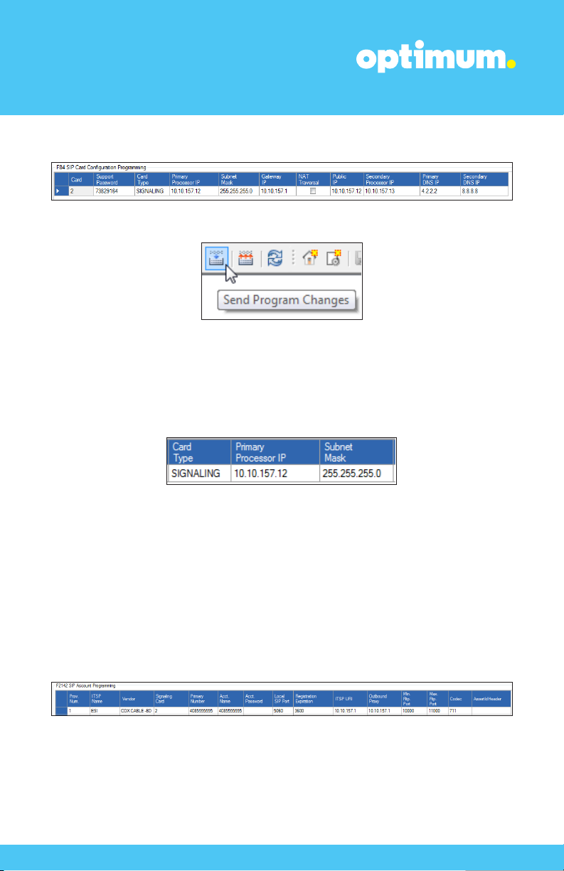
3 ESI-100 Configuration
The configuration described here assumes that the PBX is already configured
and operational with station side phones using assigned extensions or DIDs. This
configuration is based on ESI-100 version 12.5.25.0.
3
Manufacturer: ESI
Model: ESI-100
Software Version: 12.5.25.0
Does the PBX send SIP
Registration messages Ye s
(Yes/No)?
Vendor Contact: www.esi.com

ESI-100 IP-PBX
4
3.1 Network Settings
The ESI-100 system includes a management, SIP, and RTP port. They are
10.10.157.11, 10.10.157.12, & 10.10.157.13 respectively and all utilized the /24
netmask. To modify network settings first right click the site name and connect to
Network/NSP.
Navigate to Program>F8 IP Programming>F82 Local Programming>F824 NSP
IP Programming and enter the address of the management port under NSP Private
IP Address and the address of the Optimum Business Sip Trunk Adaptor under NSP
Gateway IP Address.
Next navigate to Program>F8 IP Programming>F84 SIP Card Configuration
Programming. Under Card Type what should be selected is SIGNALING. The
Primary Processor IP field is essentially the SIP port which will be used for signaling.
The IP address of the Optimum Business Sip Trunk Adaptor should be entered under
Gateway IP. The Primary Processor (SIP IP) address can be entered in the
Public IP field. The Secondary Processor IP field will contain the IP address of the
RTP port.

ESI-100 IP-PBX
5
Note: The Card number should correlate to the slot being used. In this case it was slot 2.
When done click Save followed by the Send Program Changes button above.
3.2 SIP Programming
To program SIP the SIP port must initially be given an IP address. Navigate to
Program>F8 IP Programming>F84 SIP Card Configuration Programming and
assign an IP address to the SIP port under Primary Processor IP which in this case is
10.10.157.12 /24.
Next navigate to Program>F2 CO Lines>F21 CO Lines>F214 SIP Line
Programming>F2142 SIP Account Programming. The Prov. Num. field should
be 1. The ITSP Name here was “ESI”. The selected vendor was COX CABLE –BD
and the Signaling Card was 2. Note: Due to the limited number of options under
Vendor to select, the COX CABLE –BD option was the one selected for registration
mode. VOXITAS –FS in turn was selected for Static Mode.
The Pilot DID, credentials, and SIP information should be entered in the fields that
follow. The address of the Optimum Business Sip Trunk Adaptor should be entered
under ITSP URI and Outbound Proxy. The RTP port range was “10000-11000” and
the codec 711.

ESI-100 IP-PBX
6
Now navigate to Program>F2 CO Lines>F21 CO Lines>F214 SIP Line
Programming>F2141 SIP Trunk Programming. The ITSP Name which in this case
was “ESI” should be included for SIP Trunks 24-31 as shown. ID 1 under Ring 1
(Day) represents the Auto Attendant.
Finally select Enable under F2145 Pilot Table for SIP Trunks as displayed below.
When done click Save followed by the Send Program Changes button above.

ESI-100 IP-PBX
For Static mode exclude the credential section under F2142 SIP Account
Programming and confirm the device’s SIP port address remains specified under
F84 SIP Card Configuration Programming. The vendor option can be one that
excludes the registration fields. VOXITAS -FS in this example was chosen.
3.3 Extensions/DID
To configure extensions and DIDs navigate to Program>F2 CO Lines>F22 CO
Access Deny Tables>F224 DID & DNIS/ANI Transfer. Click Add from below then
click the empty field under Number. Here is where the DID will be entered. Under
Call Fwd (Day) and Call Fwd (Night) simply right click and select an available
extension and this will be mapped to the entered DID.
The Exception field defines the default route, in this case it is the Auto Attendant
depicted as ID 1.
Navigate to Program>F2 CO Lines>F24 Caller ID and select Enabled under
Caller ID.
7

ESI-100 IP-PBX
8
To control the behavior of particular outbound numbers navigate to Program>F2
CO Lines>F22 CO Access Deny Tables>F222 Toll Restrictions and here
numbers can be allowed or denied.
Note: The Cablevision network supports Inband DTMF only. ESI uses Inband
DTMFby default and this is not an configurable option.

ESI-100 IP-PBX
9
3.4 Backup/Restore
To backup the device file simply right click the site and navigate to Backup followed
by System Programming.
Once a backup has been performed, a backup folder will appear under Program.
Right click this folder to restore.
Table of contents