PREPARATION FOR USE
Before making any connections:
•
Be
sure the receiver's power cord is
unplugged.
•
Be
sure the [POWER] button is off.
Note: To eliminate or reduce inter-
ference, use shielded audio cables for
all connections other than speaker
connections.
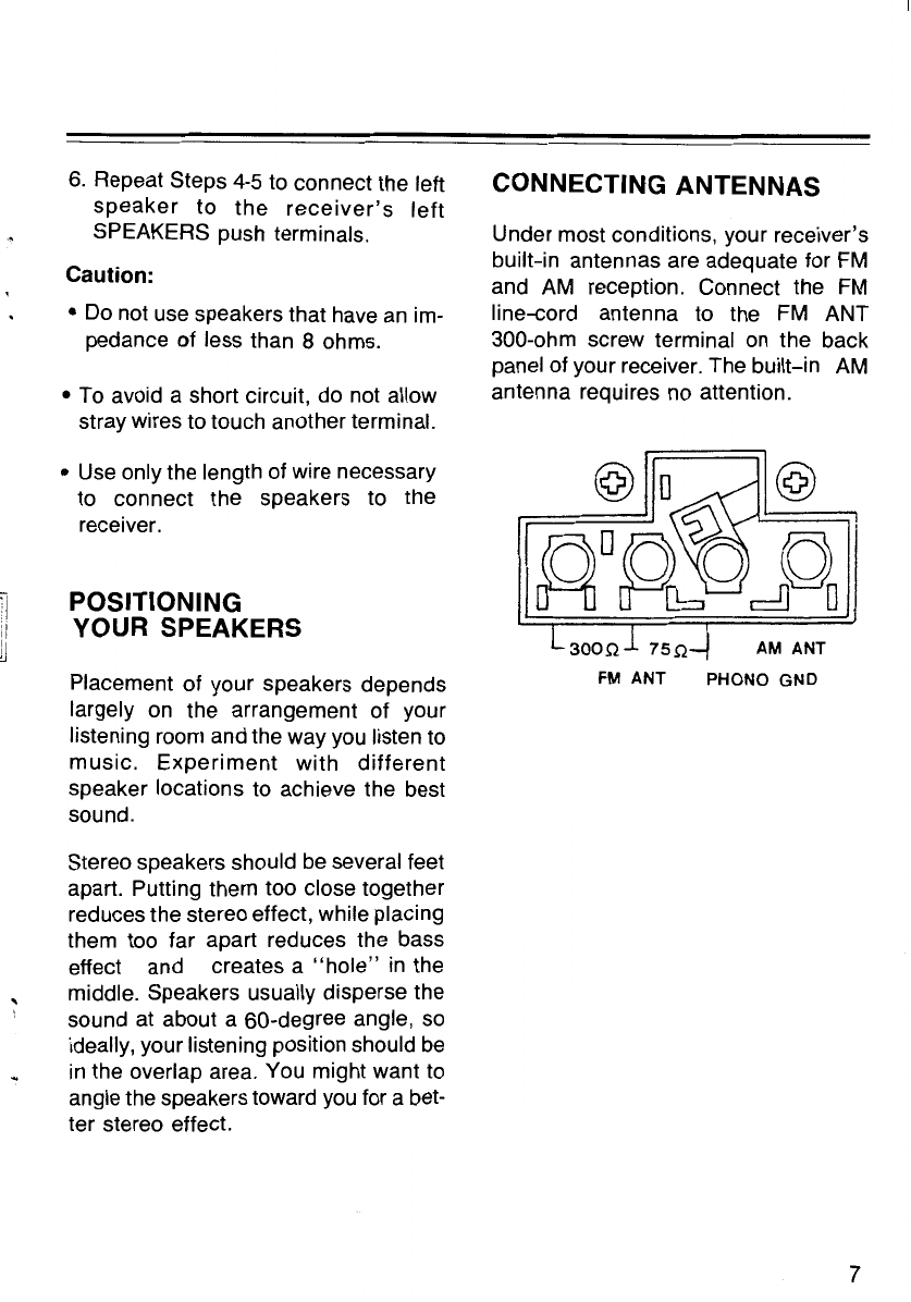
CONNECTING SPEAKERS
Your receiver is designed for use with
speakers that have
an
impedance of 8
ohms or higher. To fully enjoy the
receiver's capabilities, we recommend
that you use our Minim
us
series speaker
systems. However, you can also use
any high-efficiency standard speakers
or other types of compact speakers.
For speaker connections,
use
speaker
cable
or
1
8-1
6 gauge speaker cable
or
two-conductor wire.
We
recom-
mend that you use the shortest length
of wire possible.
Speaker wire consists of two individual
wires encased in insulation. Speaker
wire is usually color-coded or marked
with a ridge along one side to help you
make the proper connections between
your receiver and speakers.
1.
Cut your speaker wires to the length
needed to connect your speakers to
your receiver.
6
2.
Split both speaker wires approx-
imately four inches
on
each end.
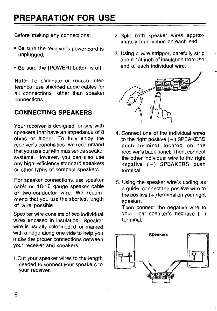
3.
Using a wire stripper, carefully strip
about 1/4 inch of insulation from the
end of each individual wire.
~
~
4.
Connect one of the individual wires
to the right positive (
+)
SPEAKERS
push
terminal
located
on
the
receiver's back panel. Then, connect
the other individual wire to the right
negative
(-)
SPEAKERS push
terminal.
5.
Using the speaker wire's coding
as
a guide, connect the positive wire to
the positive
(+)terminal
on
your right
speaker.
Then connect the negative wire to
your right speaker's negative
(-)
terminal.
SpeaKers
OPERATION
USING THE RECEIVER'S
CONTROLS
1.
Press [POWER] to turn
on
the
receiver. When the power
is
on, the
red
dial-pointer
indicator lights.
Press [POWER] again to turn off the
power.
2.
Select and prepare the desired pro-
gram source
as
described in the
following instructions.
Program Sources
AM-
Set the source selectorto
AM.
Use the turning control to select the
preferred station. When you ac-
curately tune to a station, the green
TUNED indicator lights.
FM
AUTO-
Set the source selector
the
FM
AUTO.
Use
the tuning control
to
select the preferred station. When
you
accurately tune in a station, the
green TUNED indicator lights.
If the station is broadcasting
in
stereo, the red STEREO indicator
also lights.
PHONO -Set the source selector to
PHONO. Put a record
on
your turn-
table and adjust the front panel con-
trols for the desired sound. See
"Connecting a Turntable."