OptiSpin 140 User manual

Operating Manual
Models:
140
1100S
Fiber Polishing Systems

Contents
Saftety and Care 3
Introduction 4
Set-up 5
Changing Bits 5
Squaring Bit 6
Quick Release 6
Spacing Bit 7
Model Descriptions 8
Polishing Disc 9
General Operation 13
Suggested Polishing Procedures 15
Publish Date 10/13/03

Safety
OptiSpin™ is safe to operate by most trained personnel in most
environments due to its lack of electrical components and it's
manual operation. Always wear safety glasses when handling and
polishing fiber optics to avoid possible eye injury. Dispose of any
cleaved or broken glass fibers in accordance with accepted safety
standards. Deviation from the manufacturer's recommendations
for operation of or in modification of OptiSpin™ could result in
injury to the operator.
Particular care should be taken when transporting OptiSpin due
to its considerable mass.
Avoid transporting OptiSpin™ outside of its carrying case.
Always work on a secure and stable work surface.
Care
The mild steel surfaces on OptiSpin™ are chemically protected.
This chemical protectant is a molybdenum-disulfide polymer
designed to improve corrosion protection for metal components
exposed to harsh environments. This includes immersion in most
fuels, lube oils, many solvents and acids as well as salt water.
Cleanup should be conducted with a damp cloth. Dry with a
paper towel or dry cloth.
OptiSpin™ never requires lubrication of any sort.
3

Introduction
OptiSpin™ represents a very new and logical approach to fiber polishing.
The OptiSpin™ approach will consistently yield near perfect connections
in one-half the time and with one-half the consumable materials for most
users in most applications.
Tens of millions of pre-radiused ferrules are manufactured each year by a
number of manufacturers for use in various styles of optical connector
design . Each of these ferrules is molded and machined to very exacting
specifications utilizing state -of the-art machinery. Conventional polishing
techniques aggressively reduce not only the fiber but also the ferrule itself.
Aggressive random ferrule polishing can easily alter the inherent geometry
and length of the ferrule producing a less than desirable result.
Additionally, aggressive ferrule polishing consumes both time and
materials. If a pre-radiused ferrule were manufactured out-of-spec,
conventional random polishing will not likely correct the flaw, it will more
likely preserve or magnify the flaw.
OptiSpin™ provides a non-aggressive means whereby the fiber may be
polished without danger of altering the ferrule geometry or length. If the
ferrule must be polished for aesthetic purposes, then only those sub-micron
scratches inherent to the ferrule manufacturing process must be removed
leaving the polished ferrule, essentially, with it's original geometry.
OptiSpin™ also provides a means for flat-polish. Plastic fibers and
stainless steel ferrules are a snap for OptiSpin™ .
Thank you for taking time to learn more about OptiSpin™. Please read
further about set-up, and then, polishing procedures.
4

Set-up
OptiSpin™ comes to you ready to polish . The following procedures
should be implemented only if your application requires some special
modification or if the device should require adjustment in the future.
Changing Bits
The diagram below shows the "Block " and "Bit" assembly. The bit is
affixed to the block by two screws with thumb wheels at point "A" & "B".
Removal of these screws will allow the bit to be interchanged quickly.
Point "F" in Figure 1 is the placement position for the connector and
ferrule. Bits come in various designs for various connector styles.
The block is indexed along the two stainless steel guide rods by the
rotation of the stainless steel threaded shaft.
5

Connector Lock
Directly above point "F" is a threaded hole for insertion of a 2-56 retaining
nylon screw. Use of the retainer screw is optional. The retaining screw can
hold the connector in place, hands free, while polishing.
Optical Swab
Directly below "F" is a .125 smooth hole for insertion of a standard optical
swab. Use of the optical swab is optional as well. The swab will help
"sweep" away any remaining polishing debris as well as provide a means
of introducing fluids to the polishing process, if desired
Squaring the Bit
Points "C","D", & "E" in figure 1 are adjustment ports for the bit. This 3-
point adjustment feature allows the bit to be "squared" to the polishing film
surface. Your OptiSpin™ bit was squared at the factory and no
adjustment should be required. Adjustments to the bit may be made with
an .050 allen wrench that is inserted through the adjustment ports until the
allen wrench "finds" the 3/8" long 4-40 allen screw. When turned
clockwise, the allen screws contact the backside of the bit forcing it
toward the polishing surface. Make sure you loosen the thumbwheels that
secure the bit to the block so that the bit is free to move when making
adjustments. Adjust the flat face of the bit until it is square with the
polishing surface on both axes. Now retighten the thumb wheels. It is not
necessary to alter the adjustment when changing bits. One setting should
work for all bits.
Quick Release
The insert drawing in figure 1 shows the quick release button for the block.
The button is located on the bottom of the block. Depressing the button
releases the block from the screw drive and allows the operator to slide the
block, quickly, from point to point. Place your index finger on the button,
your thumb on the top of the
6

block and depress the button. Keeping the button depressed, slide the
block to its new position and then release the button. Turn the hand wheel
three or four rotations to make sure the screw drive threads are reseated.
Spacing the Bit From the Polishing Disc
Maintaining proper spacing between the bit and polishing film disc is
necessary for efficient operation. Your unit's spacing should have already
been set properly at the factory. If there is no spacing, the polishing
medium will contact the surface of the bit causing unnecessary wear on
both bit and polishing medium. If the spacing is to great, there may be
insufficient contact between fiber/ferrule and polishing medium.
A simple way to adjust the
spacing between bit and
polishing disc is as follows:
Loosen the 3/32 allen
setscrew as shown in figure
2. This setscrew prevents
the hand wheel from
spinning on the drive shaft.
Select a solid construction
polishing disc . If you are
flat polishing primarily,
select the glass disc. If you
are polishing pre-radiused
ferrules primarily, use the
solid disc with rubber surface. Mount the selected polishing disc on the
polishing wheel with the bit of your choice previously installed and
squared. Loosen the tensioning nut until the polishing medium contacts the
bit. Pull the hand wheel back until a gap exists between bit and polishing
medium. Place an ordinary piece of typing paper between the bit and the
polishing paper and then release the hand wheel so that the paper is caught
between the bit and the polishing medium.
7

You should be able to feel some wiggle in the hand wheel if the hand
wheel is moved back and forth in the direction indicated by the arrows in
figure 3. Turn the tensioning nut clockwise in small increments until the
wiggle is gone. Tighten the setscrew. If the unit is spaced properly, the
polishing medium should not contact the bit and you should not be able to
insert more than two thicknesses' of paper in the space created.
Models 140, 1100S
• The Model 140 has a fixed gear ratio. This unit indexes the fiber across
the polishing film at a rate of 140µm per 360º rotation of the polishing
disc. This unit is used primarily for the denubbing of glass fibers. It may be
used for polishing of plastic fibers and other limited polishing
operations.
• The Model 1100S has a variable gear ratio. The unit may be shifted
between 140µm indexing rates and 1100µm indexing rates. This unit will
perform all denubbing and final polishing actions for all fibers.
8

Polishing Discs
Polishing discs are manufactured in four basic styles and all serve different
purposes in the polishing process. Always select the properly designed
polishing disc for your application. Polishing discs may be used with many
commonly available polishing films. The discs are attached to the polishing
wheel via small magnetic discs adhered to the back of the polishing disc.
To change discs: Turn the polishing wheel slot vertical with the open end
of the slot facing up. Pull the hand wheel away from the block creating a
gap between the polishing wheel and the bit. Start one of the magnetic
discs into the slot and slide the disc down until it seats at the closed end of
the slot. Press the remaining magnetic disc into its seat until the polishing
disc seats against the polishing wheel along its entire circumference. When
removing a polishing disc, repeat the same early procedures described
above and, with the open end of the polishing wheel slot up, tip the top of
the disc away from the polishing wheel. Then pull the polishing disc
straight up and away to remove.
The Flat disc is constructed of 3/16" thick
silica glass. This disc is used, primarily, for
plastic fibers and grinding operations.
Either plain or PSA backed polishing films
may be used. Plain-backed films may be
attached with just a few drops of water.
Most polishing is done with the machine set
at a 1100µm indexing rate. You may work
from inside to outside or vice-versa. Optical
swabs may be inserted with this disc for
contaminate control
9

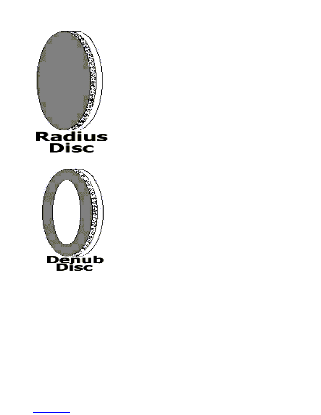
The Radius disc has a 1/16" 70 durometer
neoprene pad adhered to its entire surface.
This disc is used for epoxy removal as well as
final polishing stages of connectors with pre-
radiused ferrules. Either plain or PSA backed
polishing films may be used. Plain backed
films may be attached with just a few drops of
water. Most polishing is done with the
machine set at a 1100µm indexing rate. You
may work from inside to outside or vice-versa.
Optical swabs may be inserted with this disc
for contaminate control.
The Denub disc is an annular ring whose solid
surface is covered with 1/16" 70 durometer
neoprene rubber.
As its name implies, the Denub disc is used
for denubbing glass fibers. Only 4" adhesive
or PSA backed polishing film discs may be
used with the Denub Disc. Any grit film may
be used but 3-5µm is most effective. A single
4" diameter 5µm silicon carbide disc will
denub several dozen fibers assuming a cleave length of .010-.015".
Application of an adhesive backed disc forms a "drum head" over the
center portion of the disc. Since only air exists behind the polish paper, it's
very similar to an "air polish" only faster and with fewer broken fibers. A
typical denubbing process takes only about 15 seconds.
10

The process begins by making sure your machine is first set set to 140µm
increments and that the bit is set at the center of the polishing disc. You
want to make sure that the ferrule starts at the center of the Denub disc so
that you can work your way out. Remember that the block has a "quick
release" enabling you to move the bit quickly. Next, insert the cleaved
connector into the bit.
Figure 4 shows proper insertion of the connector, Notice how the drawing
reflects that the fiber nub has slightly indented the polishing film. This
shows that the nub is in contact with the polish film and ready to be
denubbed. When first getting started it is wise to stop the connector
insertion at the first sign of contact with the polishing film. If the cleave is
long and/or too much pressure is applied, the fiber can break. The Denub
disc is capable of reducing very long fiber nubs but it is wise to keep your
cleaves as short as practical for safety and speed. Work conservatively at
first, until you get the feel, and then work on speed later.
11

Once the fiber nub has dented the polishing film, hold the connector in one
position and begin turning the hand wheel clockwise , slowly, for a turn or
two and then pick up speed. The
amount of turns required to complete denubbing will vary greatly
depending on cleave length, polish grit, and pressure. 20 rotations of the
hand wheel would be about average. Many polishing films will put forth a
very audible sound as the fiber nub is being reduced. That tone will change
when the nub is reduced to the point when the polishing film contacts the
ferrule or epoxy bead.
DO NOT attempt to denub fibers on the outer 5/8" of the Denub Disc.
This area is reserved for polishing film attachment and should not be used
in the denubbing process.
DO NOT insert a foam optical swab while denubbing.
One-Step discs are of the same construction as
denubbing discs but the rubber surface actually
extends beyond the solid surface.
One-Step discs perform denubbing, epoxy removal
and final polish procedures for glass fibers without
changing discs or polishing films. Usually, these discs
are used in commercial polish applications
(multimode) where inspection beyond 200X is not
required.
One-Step discs have three separate polishing
zones within a single disc.
Denubbing of the cleaved fiber is begun in
zone 1. Final denubbing and epoxy removal
are accomplished in zone 2. Zone 3 removes
any remaining epoxy and finishes the
fiber/ferrule polish.
12

General Operation
OptiSpin™ gives the operator greater control over the polishing process
and more tools to aid in production of a quality product. No longer are you
working upside down and blind. OptiSpin™ allows you to see, hear, and
feel the polishing process as it occurs.
Automatic indexing of the fiber across the polishing surface accomplishes
several things.
•Nearly 100% usage of the polishing film.
• Effort and time expended is nearly 100% efficient because you
aren't wasting time polishing over expended film.
•Contamination is greatly reduced because you are always on fresh
polishing film.
OptiSpin™ also offers another unique advantage . The spool and handle
system, pictured below, is five times more efficient than the figure eight
coil when gathering cable.
13

The polishing motion of OptiSpin™ is like the spool and handle previously
depicted. The polishing motion is in a continuous direction saving both
time and effort.
The vertical design of OptiSpin™ not only allows the operator to see the
polishing process in progress but also provides another great advantage. As
the drawing below demonstrates, gravity works in your favor with
OptiSpin™.
The vertical orientation of the polishing wheel and disc allows polishing
debris to fall clear of critical polishing surfaces rather than accumulating
on horizontal polishing surfaces.
Depending on the model purchased, the ferrule and fiber are indexed
across the polishing film at either 140µm or 1100µm rates for each 360°
rotation of the polishing wheel. Usually the connector is placed into the
proper bit for the application and hand pressure is applied to the connector
housing supplying the necessary pressure to accomplish the polishing task.
Generally, one starts from the center of the disc and works to the outside.
This is always true with Denub and One-Step discs but Radius and Flat
discs can be used in either direction. You may elect to use the nylon
setscrew in the top of the bit to hold the connector in place, hands free, but
this is a safe option only with Radius and
Flat discs.
14

Generally, very little pressure is applied to accomplish the polishing
procedure. As mentioned in the introduction, OptiSpin™ uses a non-
aggressive approach to fiber and ferrule polishing. Complete instructions
for many types of polishing applications can be found in the following
section.
Suggested Polishing Procedures
The OptiSpin™ system uses fewer steps than conventional polishing
methods. Fewer steps are required due to the efficiency of the OptiSpin™
concept. OptiSpin™ also produces near-perfect connectors with respect
to ferrule geometry. This is of particular importance when back-
reflectance levels are at issue. It does not make sense to alter the length
and geometry of a pre-radiused ferrule when the length and geometry are
already near perfect. As mentioned earlier, if the inherent geometry of the
ferrule is flawed, random polishing techniques will not likely correct the
flaw. If we use non-aggressive polishing techniques, the inherent
perfection of the pre-radiused ferrule is preserved with respect to radius of
curvature and apex offset. We then need only concern ourselves with
issues of fiber undercut (fiber end over polished below the ferrule surface)
and fiber protrusion (fiber end under polished above the ferrule surface.).
OptiSpin™ provides many tools for your use. These tools, when
combined with the various grades of polish film available on the market
today, provide many potential ways to achieve the same goal. The
following are a few that we have found to work well. When a particular
type polish disc is called for in the procedures, please refer to the
preceding Polishing Discs section for a description of those polishing discs
and the instructions for their use
15

Plastic Fibers
Plastic fibers are generally polished with a flat geometry. Use the Flat
polish disc for this application. Typically, plastic fibers are finish polished
with films ranging from .3 to 3µm. Depending on the amount of fiber left
protruding from the ferrule, any of the films in this range may produce a
finished polish without changing discs or polish films. For example;
ONE DISC METHOD:
1. Apply a 1µm aluminum oxide polish film to the Flat disc and then load
the disc on the machine.
2. Position the bit so that the ferrule is at the center of the disc.
3. Make sure that the indexing rate is set to 140µm.
4. Insert the connector into the bit and exert pressure so that the plastic
fiber contacts the polish film solidly.
5. Turn the hand wheel clockwise while maintaining pressure.
6. Watch for the polish scuffmark on the polish film to broaden, indicating
that the fiber has been reduced and that the ferrule and fiber are now
flush.
7. Inspect for flaws.
Note: Depending on how much film was used on the first connector,
position the next connector where the first left off so that polish film usage
is maximized.
TWO DISC METHOD:
1. Apply a 3µm film on one disc and a .3µm on a second disc.
2. Polish with the 3µm until just a bit of fiber nub remains.
3. Switch to the .3µm disc and finish.
Multi-Mode Fibers
First a discussion about epoxy beads. OptiSpin™ does not require that
any epoxy bead is present for the denubbing process. It is very unusual to
break a fiber while using the Denub Disc and while exercising ordinary
16

care and compliance with instructions. Excess epoxy on the ferrule
surface simply means that more time and materials must be expended to
remove it. If you are injecting epoxy into the ferrule, we recommend that
you inject only enough epoxy to insure that the glue line between fiber and
ferrule is totally filled. This usually means that you stop injection
immediately upon seeing the first sign of epoxy as it appears on the ferrule
surface. This will still leave a small epoxy bead that is easily removed
using the following procedures.
1. Apply 5µm silicon carbide polish film to the Denub Disc,load disc on
machine.
2. Move bit so that ferrule starts in center of disc, then set to 140µm index
rate..
3. Insert connector into bit so that cleaved fiber nub dents polishing film
slightly.
4. Rotate polishing wheel clockwise until:
A.Fiber is flush with epoxy bead
B.If no epoxy bead is present, rotate until polish film contacts ferrule
surface leaving 5-8µm of fiber protruding from the ferrule surface.
You know 5-8µm of fiber remains when you cannot feel the fiber nub
protruding from the ferrule and there are no 5µm polish scratch
visible within 125µm, in any direction, of the fiber cladding.
5. Apply .3 to 1µm aluminum oxide polish film to Radius disc.
6. Set machine to 1100µm index rate. Work inside out or outside in.
7. Make CERTAIN that fiber is properly denubbed.
8. Insert connector in bit and apply ferrule pressure to polish film.
9. Reduce fiber/epoxy until ferrule is clean and fiber flush with ferrule
surface.
Note: If one pass across polishing film is insufficient to remove epoxy, you
are either using too much epoxy or not applying sufficient pressure.
17

Singlemode Fibers
Now a little more about denubbing. You will note in the previously
described discussion and procedures for multimode fibers that care is
taken not to allow the coarser grit films to remove the fiber nub flush with
the ferrule surface. This serves two purposes: First, the best way to remove
deep scratches from the ferrule surface is not to put them in the first place.
If 5µm polish film is allowed to remove fiber/epoxy all the way to the
ferrule surface, then deep scratches can occur in the ferrule surface and
the fiber end will be severely pitted. The only way to remove the pits and
scratches is to begin reducing the ferrule surface along with the fiber. This
we do not want to do. It is time consuming, a wasteful exercise in materials
and we are in danger of altering the inherent ferrule geometry. Secondly,
and important to Singlemode polish procedure, is the effect that coarser
grit films can have on the cladding of the fiber itself.
18

Denubbing with coarse grit films can damage the cladding edges. Pieces
and chips of glass are torn from the cladding edge by the more abrasive
polishing films. These chips can extend down the cladding wall for several
microns as indicated by Figure 5. When the fiber is flush with the ferrule
surface and observed with 400X inspection scopes, these chips can appear
as if they are epoxy residue or some other contaminate stuck around the
perimeter of the glue line (Figure 6). At this point, the only way to restore
a contiguous glue line is to remove several microns of both fiber and
ferrule. While there is no clear evidence that this problem causes
performance problems in multimode, it is certainly an aesthetic problem. It
may also likely create a problem for the finer polish stages that are
required for singlemode applications. Since the cladding edges have been
weakened, small pieces of cladding can pop loose during final polish. Even
epoxy will not always protect the cladding perimeter from this problem.
These small pieces of glass are perfectly capable of scratching both ferrule
and fiber. It is particularly important in singlemode applications to insure
that the cladding perimeter edge is whole and intact for both aesthetic and
practical reasons. To insure that intact cladding edges are maintained, no
polishing films above 1µm should be used with less than 5µm of fiber nub
extending above the ferrule.
1. Follow the instructions given for multimode fibers through step 9
2. Apply .1 to 1µm diamond film to Radius Disc.
3. Remove scratches from ferrule surface (only a very few rotations)
4. Apply .02-.05µm super polish film (your choice).
5. Super polish fiber and ferrule (only a few rotations).
19

Alternative Polish Procedure
1. Follow the instructions given for multimode through step 9
2.Apply .1 to.5µm diamond film to Radius Disc using light pressure.
3.Remove scratches from ferrule surface (only a very few rotations)
This will yield a scratch free polish under 400x inspection.
Note: As everyone agrees, the final stage of singlemode polish can be a
real pain. Sometimes it seems more luck than skill in achieving a scratch
free polish. OptiSpin™ offers two suggestions to make the process less
painful. Use the optical swab in this final stage. You can dip it in alcohol or
other fluid if you wish. The optical swab tracks the ferrule and removes
any leftover contaminates on the polishing film. You still have to worry
about buildup of loosened polishing film grit on the ferrule and fiber itself.
Our advice is to make a rotation, clean the ferrule end, then make another
rotation etc. If you keep the polishing film and the fiber end clear of
contamination, you should have fewer problems.
One-Step Polish
It is imperative that only a small epoxy bead remain for the one step
process and that the cleaved fiber is no longer than .015 inch (standard
cleave length).
1. Apply .3 to1µm aluminum oxide PSA backed polishing film to the
One-step Disc.
2. Set the machine to the 140µm index rate.
3. Place the bit at the center of the disc.
4. Insert the connector until the polish film dents.
5. Rotate clockwise making sure that the fiber does not cut the abrasive.
Note: if the fiber did not cleave properly (flat) and has a sharp point, it
may cut the abrasive surface of the polishing film and result in a broken
fiber. You can avoid this problem by giving the fiber a quick air polish
with 3 to 5µm polishing film. Just 4 or 5 passes across the film is all it
takes to knock down a sharp point on the fiber and to insure that you
will not snap the fiber nub. 20
This manual suits for next models
1
Table of contents