kincrome K13245 User manual

INDUSTRIAL 16PC ANGLE SANDER KIT INDUSTRIAL 16PC ANGLE SANDER KIT
INDUSTRIAL
16PC AIR ANGLE
SANDER KIT
K13245
ED1 December 15
VARIABLE
SPEED
WHEELS
75MM
UNIQUE
50MM
&
2
YEAR
WARRANTY
TWIN BEARING
SYSTEM

1
INDUSTRIAL 16PC ANGLE SANDER KIT
Table of Contents
Know Your Product ...................................................................................................1
General Safety Instructions .....................................................................................2
Additional Safety Instructions..................................................................................3-4
Assembly...................................................................................................................4
Operation...................................................................................................................4-5
Maintenance & Warranty .........................................................................................5-6
Parts Breakdown......................................................................................................7
Know your product
1. Spindle Adaptor
2. Spindle
3. Right angle head
4. Sander body
5. Speed Selector
6. Swivel Exhaust
7. Air Inlet
8. Trigger Lock-Off
9. Trigger
10. 2 X Spindle Spanner
11. 50MM Backing Pad
12. 75MM Backing Pad
13. 50MM Abrasive Disc (Brown)
14. 50MM Abrasive Disc (Blue)
15. 50MM Abrasive Disc (Maroon)
16. 75MM Abrasive Disc (Brown)
17. 75MM Abrasive Disc (Blue)
18. 75MM Abrasive Disc (Maroon)
19. Nitto Style Fitting
Model No:................................................................................................................... K13245
Description: .............................................................................................................. Industrial 16PC Angle Sander Kit
Air Inlet: .................................................................................................................... 1/4”
Average Air Consumption:....................................................................................... 99 LPM (3.5CFM)
Free Speed: ............................................................................................................... 15,000 RPM
Air Pressure (max.): ................................................................................................ 90PSI
Hose Length (max.): ................................................................................................. 10 Meters
Hose Diameter (min.):.............................................................................................. 10mm (3/8”)
Weight: ....................................................................................................................... 1.6Kg
3
1
2
4
5
7
8
9
10
11 12 13 14 15
16 17 18
19
6

2
INDUSTRIAL 16PC ANGLE SANDER KIT INDUSTRIAL 16PC ANGLE SANDER KIT
General Safety Warnings
Save all warnings and instructions for future reference.
WARNING! Read all safety warnings and all instructions. Failure to follow the warnings and instructions may
result in serious injury.
1) Work Area
a. Keep the work area clean and well lit. Cluttered benches and dark areas increase the risks of electric shock, fire, and
injury to persons.
b. Keep bystanders, children, and visitors away while operating the tool. Distractions can result in the loss of control of
the tool.
c. Keep children and bystanders away while operating any powered products. Distractions can cause you to lose control.
2) Personal Safety
a. Stay alert. Watch what you are doing and use common sense when operating the tool. Do not use the tool while tired or
under the influence of drugs, alcohol, or medication. A moment of inattention while operating the tool increases the risk of
injury to persons.
b. Dress properly. Do not wear loose clothing or jewellery. Contain long hair. Keep hair, clothing, and gloves away from
moving parts. Loose clothes, jewellery, or long hair increases the risk of injury to persons as a result of being caught in
moving parts.
c. Avoid unintentional starting. Be sure the switch is off before connecting to the air supply. Do not carry the tool with your
finger on the switch or connect the tool to the air supply with the switch on.
d. Remove adjusting keys and wrenches before turning the tool on. A wrench or a key that is left attached to a rotating part of
the tool increases the risk of personal injury.
e. Do not overreach. Keep proper footing and balance at all times.Proper footing and balance enables better control of the tool
in unexpected situations.
f. Use safety equipment. A dust mask, non-skid safety shoes and a hard hat must be used for the applicable conditions. Wear
heavy-duty work gloves during use.
g. Always wear eye protection. Wear approved safety eye protection.
h. Always wear hearing protection when using the tool. Prolonged exposure to high intensity noise can contribute to
hearing loss.
3) Tool Use and Care
a. Use clamps or other practical ways to secure and support the workpiece to a stable platform. Holding the work by hand or
against the body is unstable and can lead to loss of control.
b. Do not force the tool. Use the correct tool for the application. The correct tool will do the job better and safer at the rate for
which the tool is designed.
c. Do not use the tool if the switch does not turn the tool on or off. Any tool that cannot be controlled with the switch is
dangerous and must be repaired, by an authorised repair agent.
d. Disconnect the tool from the air source before making any adjustments, changing accessories, or storing the tool. Such
preventive safety measures reduce the risk of starting the tool unintentionally. Turn off and detach the air supply, safely
discharge any residual air pressure, and release the throttle and/or turn the switch to its off position before leaving the
work area.
e. Store the tool when it is idle out of reach of children and other untrained persons. A tool is dangerous in the hands of
untrained users.
f. Maintain the tool with care. A properly maintained tool is easier to control.
g. Check for misalignment or binding of moving parts, breakage of parts, and any other condition that affects the tool’s
operation. If damaged, have the tool serviced before using, at an authoriesd Kincrome repair agent.Many accidents are
caused by poorly maintained tools.
h. Use only accessories that are identified by the manufacturer for the specific tool model. Use of an accessory not intended
for use with the specific tool model, increases the risk of injury to persons.

3
INDUSTRIAL 16PC ANGLE SANDER KIT
4) Service
a. Tool service must be performed only by qualified repair personnel.
b. When servicing a tool, use only identical replacement parts. Use only authorized parts.
c. Use only the lubricants specified by the manufacturer.
5) Additional Safety Warnings
a. The warnings and precautions discussed in this manual cannot cover all possible conditions and situations that may
occur. It must be understood by the operator that common sense and caution are factors which cannot be built into this
product, but must be supplied by the operator.
b. Only use with accessories rated to handle the forces exerted by this tool during operation. Other accessories not designed
for the forces generated may break and forcefully launch pieces.
c. Attach all accessories properly to the tool before connecting the air supply. A loose accessory may detach or break during
operation.
d. Thoroughly read and understand the manual for the air compressor used to power this tool. Install an in-line shutoff
valve to allow immediate control over the air supply in an emergency, even if a hose is ruptured.
e. Use this tool with both hands only. Using tools with only one hand can result in loss of control.
f. Do not lay the tool down until it has come to a complete stop. Moving parts can grab the surface and pull the tool out of
your control.
g. Do not force the tool. Use a larger one if needed.
h. Do not hold adapters or discs during use.
i. Anyone using vibrating tools regularly, or for an extended period should first be examined by a doctor and then have
regular medical check-ups to ensure medical problems are not being caused or worsened from use. Pregnant women
or people who have impaired blood circulation to the hand, past hand injuries, nervous system disorders, diabetes, or
Raynaud’s Disease should not use this tool. If you feel any symptoms related to vibration (such as tingling, numbness, and
white or blue fingers), immediantly discontinue use and seek medical advice as soon as possible.
j. Do not smoke during use. Nicotine reduces the blood supply to the hands and fingers, increasing the risk of vibration related
injury.
k. Wear suitable gloves to reduce the vibration effects on the user.
6) Description of Symbols
The following symbols could be shown on the tool:
Read the instruction manual before use. Risk of Explosion
Wear Ear Protection Wear Eye Protection
no No-load speed, Free Speed CFM Cubic Feet per Minute flow
.../min, RPM Revolutions or reciprocation per minute SCFM Cubic Feet per Minute flow at
standard conditions
PSI Pounds per square inch of pressure NPT National pipe thread, tapered
ft-lb Foot-pounds of torque BPM Beats/ Blows per minute
Nm Newton meters of force BSP British standard pipe

4
INDUSTRIAL 16PC ANGLE SANDER KIT INDUSTRIAL 16PC ANGLE SANDER KIT
7) Additional Safety instruction for Air Sanders
1. Hold air tool by insulated gripping surfaces, as the sanding pad may contact its own air hose. Cutting a “live” air hose may
cause hose to rupture and pose a hazard to yourself and others.
2. Disposing of dust. Be extremely careful of dust disposal, materials in fine particle form may be explosive. Do not throw sanding
dust on an open fire. Spontaneous combustion, may in time, result from a mixture of oil or water with dust particles.
3. Always wear eye protection and a dust mask for dusty applications and when sanding overhead. Sanding particles can be
absorbed by your eyes and inhaled easily and may cause health complications.
4. Use special precautions when sanding chemically pressure treated timber, paint that may be lead based, or any other
materials that may contain carcinogens. A suitable breathing respirator and protective clothing must be worn by all persons
entering the work area. Work should be sealed by plastic sheeting and persons not protected should be kept out until work area
is thoroughly cleaned.
5. Do not ‘wet sand’ with this sander. Liquids entering the motor housing will cause corrosion.
6. Do not use sandpaper intended for larger sanding pads. Larger sandpaper will extend beyond the sanding pad causing
snagging, tearing of the paper or kick-back. Extra paper extending beyond the sanding pad can also cause serious lacerations.
WARNING! Some dust created by power sanding, sawing, grinding, drilling and other construction activities contain
chemicals known to cause cancer, birth defects or other reproductive harm. Some examples of these chemicals are:
• Lead from lead-based paints;
• Crystalline silica from bricks, cement and other masonry products, and;
• Arsenic and chromium from chemically-treated timber.
Your risk from these exposures varies, depending on how often you do this type of work. To reduce your exposure to these chemicals:
work in a well-ventilated area and work with approved safety equipment, such as dust masks that are specially designed to filter out
microscopic particles.
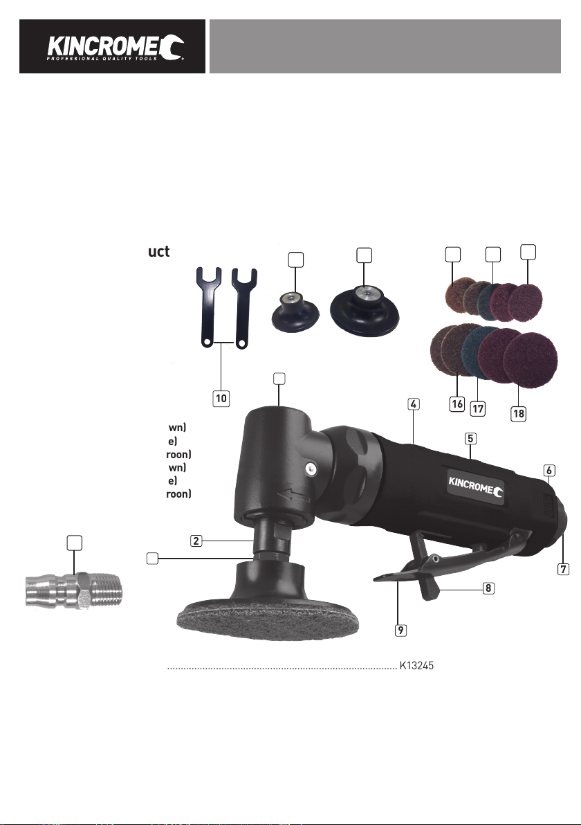
8) Assembly
Attaching/Removing a sanding pad
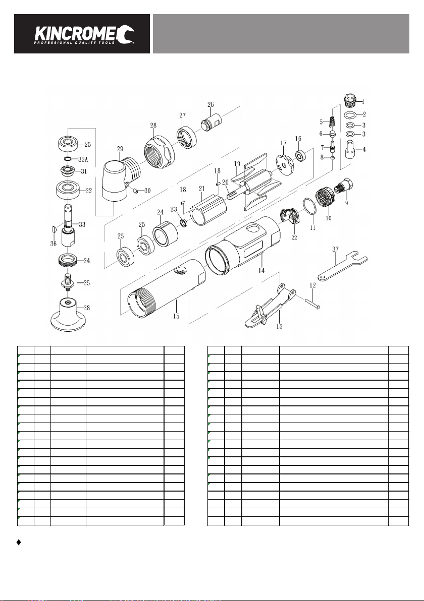
1. Firstly you must attach the spindle adaptor (1) to the spindle (2), by screwing it in by hand, then tighten it in using the spindle
spanners (10).
2. Once the spindle adaptor (1) has been firmly attached, then select either the 50mm backing pad (11) or the 75mm backing pad
(12). Once you have selected which pad would be most suitable for the job, then line up the threads and screw in tightly using
your hands.
3. Once you have chosen the suitable backing pad (11 or 12) then select the appropriate sanding disc (13-18), and screw in by hand
to the face of the backing pad (do not over tighten).
9) Before Starting
TO PREVENT SERIOUS INJURY FROM EXPLOSION:
Verify compressor is off before setup. Use only clean, dry, regulated,
compressed air to power this tool. Do not use oxygen, carbon dioxide,
combustible gases, or any other bottled gas as a power source for this
tool.
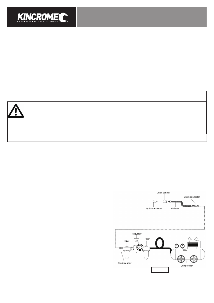
1. It is recommended a filter, regulator with pressure gauge, oiler,
in-line shut-off valve, and quick coupler be fitted for optimal
operation, as shown on Figure A.
2. An in-line shut-off ball valve is an important safety device,
it will shut-off the air supply even if the air hose is ruptured.
The shut-off valve should be a ball valve because it can be
closed quickly.
Note: If an automatic oiler system is not used, add a 4 to 5 drops of
Kincrome Air Tool Oil to the air inlet (7) before operation. Add 1-2
more drops every hour of continual use.
3. Attach an air hose to the compressor’s air outlet. Connect the air hose to the air inlet (7) of the tool. Other components, such as
a quick connect fitting and quick connect coupler, will make operation more efficient, but are not required.
Figure A

5
INDUSTRIAL 16PC ANGLE SANDER KIT
WARNING! Do not install a quick coupler directly on the tool. Couplers contains an air valve that will allow the air tool to
retain pressure and inadvertently operate after the air supply is disconnected.
4. The air hose must be long enough to reach the work area and allow free movement while working.
5. Turn on the air compressor according to the manufacturer’s directions and allow the tank to build up pressure until it cuts-off.
6. Adjust the air compressor’s regulator so that the air output is at the tools recommended working pressure, the output must not
exceed the tool’s maximum air pressure at any time. Adjust the pressure gradually, while checking the air output gauge to set
the optimal pressure range.
7. Inspect all air connections for leaks. Repair any leaks.
8. If the tool is not be used, turn off and detach the air supply, safely discharge any residual air pressure, and release the trigger (9)
and/or turn the tools switch to its off position to prevent inadvertent operation.
10) Operation
1. Screw in Nitto Style Fitting (19) to the air inlet (7). Thread (teflon) tape may be required to ensure a leak free seal.
2. The ultimate speed of the sander can be adjusted up or down by turning the speed selector to the left or right with a flat blade
screw driver (screw driver not included)
3. Make sure air supply has been disconnected from the tool.
4. Select the most suitable abrasives disc (13-18) for the job at hand, and screw onto suitable backing pad (11 or 12)
5. Once you have selected the suitable abrasive disc, start the sander by pushing the trigger lock off (8), towards the sander body
(4), then gently squeeze the trigger (9).
6. Start the angle sander and bring the sanding disc (13-18), slowly and evenly to the surface of the material. Moving the sanding
disc back and fourth overlapping the desired area.
7. Do not apply to much pressure, let the sander do the work for you.
8. Remove the sanding disc from the work surface before stopping the sander.
Note: Regularly check the sanding pad for wear, always change a cracked or damaged disc.
9. If tool requires more power to accomplish task, ensure that the tool is receiving sufficient, un-obstructed airflow.
Increase/decrease the pressure (PSI) output of regulator ensuring you do not exceed the rated maximum inlet air pressure of
the tool (90PSI).
Caution: If tool still does not have sufficient force at maximum pressure and sufficient airflow, then a larger tool may be required.
11) Cleaning, Maintenance, and Lubrication
Note: These procedures are in addition to the regular checks and maintenance explained as part of the regular operation of the
air-operated tool. The air motor and bearing uses compressed air to power the tool. Moisture in compressed air will rust the motor
components, you must lubricate the motor with Kincrome Air Tool Oil daily.
Lubrication
1. Disconnect the tool from the air supply holding it so the air inlet (6) faces up.
2. Hold the trigger (9) down and put 4 to 5 drops of Kincrome Air Tool Oil in the air inlet. Holding the trigger down helps circulate oil
in the motor.
3. Connect the tool to air supply, cover the exhaust (6) with a towel and run for a few seconds.
WARNING! Any excess oil in the motor is immediately expelled from the swivel exhaust (6) .Always swivel the exhaust (6)
away from people or objects.
Storage
1. Avoid storing the tool in a location subject to high humidity. If the tool is left as it is used, the residual moisture inside the tool can
cause rust. Before storing and after operation, oil the tool and run it for a short time.
2. Regular inspection should be carried out of spindles, threads, and clamping devices irrespect of wear.

6
INDUSTRIAL 16PC ANGLE SANDER KIT INDUSTRIAL 16PC ANGLE SANDER KIT
12) Warranty
Warranty given by Kincrome Australia Pty Ltd of 3 Lakeview Drive, Caribbean Park, Scoresby, Victoria (Tel 1300 657 528). The applicable
warranty period (24 months) commences on the date that the product is purchased. If this product has materials or workmanship defects
(other than defects caused by abnormal or non warranted use) you can, at your cost, send the product to place of purchase, an autho-
rised Kincrome service agent or one of Kincromes addresses for repair or replacement. Your rights under this warranty are in addion to
any other rights you have under the Australian Consumer Law or other applicable laws. Our goods come with guarantees that cannot be
excluded under the Australian Consumer Law. You are entled to a replacement or refund for a major failure and compensaon for any
other reasonably foreseeable loss or damage. You are also entled to have the goods repaired or replaced if the goods fail to be of ac-
ceptable quality and the failure does not amount to a major failure. For further details please visit www.kincrome.com.au or call us. Due
to minor changes in design or manufacture, the product you purchase may somemes dier from the one shown on the packaging.
IMPORTANT! If the tool fails to operate correctly, call customer service on 1800 657 528 for advice on the best resoluon for your situa-
on. If a resoluon cannot be achieved over the phone please take the tool and all related accessories to an authorised service centre or
place of purchase showing proof of purchase for assistance.

7
INDUSTRIAL 16PC ANGLE SANDER KIT
13) Parts Breakdown
NO PARTS NO DESCRIPTION
Q'TY NO PARTS NO DESCRIPTION Q'TY
01 K13245-1 SCREW 1 21 K13245-21 CYLINDER 1
02 K13245-2 O-RING (P12) 1 22 K13245-22 CONE MUFFLER 1
03 K13245-3 O-RING (P8) 2 23 K13245-23 BEARING SPACER 1
04 K13245-4 AIR REGULATOR 1 24 K13245-24 FRONT PLATE 1
05 K13245-5 SPRING 1 25 K13245-25 BEARING (608ZZ) 3
06 K13245-6 VALVE STEM BUSHING 1 26 K13245-26 BEVEL GEAR (12T) 1
07 K13245-7 VALVE STEM 1 27 K13245-27 NUT 1
08 K13245-8 O-RING (3.5*1.4) 1 28 K13245-28 CLAMP NUT 1
09 K13245-9 AIR INLET 1 29 K13245-29 ANGLE HOUSING 1
10 K13245-10 EXHAUST SLEEVE 1 30 K13245-30 OIL CUP(3/16") 1
11 K13245-11 O-RING (26.7*1.78) 1 31 K13245-31 BEVEL GEAR (17T) 1
12 32 K13245-32 BEARING (6000ZZ) 1
13 ♦K13245-13 LEVER 1 33 K13245-33 SHAFT 1
14 K13245-14 PROTECTING RUBBER 1 33A K13245-33A SNAP RING 1
15 K13245-15 HOUSING 1 34 K13245-34 CLAMP NUT 1
16 K13245-16 BEARING (696ZZ) 1 35 ♦K13245-35 ADAPTOR 1
17 K13245-17 REAR PLATE 1 36 ♦K13245-36 KEY 1
18 K13245-18 PIN(2.5*6) 2 37 ♦K13245-37 SPINDLE SPANNER(14MM) 2
19 ♦K13245-19 ROTOR BLADE 4 38 ♦K13245-38 PAD (50MM) 1
20 K13245-20 ROTOR 1 39 ♦K13245-39 PAD (75MM) 1
Kincrome reserve the right to change spare parts at any time without notice
Indicates stocked spare parts

8
INDUSTRIAL 16PC ANGLE SANDER KIT INDUSTRIAL 16PC ANGLE SANDER KIT
Notes:

www.kincrome.com.au
Table of contents
Other kincrome Sander manuals