manuals.online logo
Brands
  1. Home
  2. •
  3. Brands
  4. •
  5. OPTO 22
  6. •
  7. Adapter
  8. •
  9. OPTO 22 SNAP-RCK-M2B User manual

OPTO 22 SNAP-RCK-M2B User manual

SNAP-RCK-M2B Rack Adapter Installation
PA G E
1
TECHNICAL NOTE
Form 1695-080710
SNAP-RCK-M2B Rack Adapter Installation
Introduction
SNAP PAC I/O processors (brains and rack-mounted controllers) are
designed to mount on SNAP PAC racks. However, if you have an
older system and you need to use a SNAP PAC brain or rack-
mounted controller on an existing SNAP B-series rack, the SNAP-
RCK-M2B rack adapter makes it possible.
The adapter works with the following part numbers:
Important Notes
Change in height: The adapter adds 0.675 inches (1.715 cm) to
the overall height of the unit.
Change in connector location: After installation of the adapter,
the brain or controller’s position will be reversed on the rack (as well
as being higher in relation to the rack), and letters on the lid will be
upside down. Make sure that cables can still reach the connectors
on the processor.
No new features: The adapter does not change the capabilities of
the rack. For example, four-channel digital modules still cannot be
placed in module positions 8 and higher. In order to use newer
features on the brain or controller, it must be on a SNAP PAC rack (or
an M-series rack, such as the SNAP-M64).
Installing the Adapter
Before installing the rack adapter, read Opto 22 form #1688, the
SNAP PAC System Migration Technical Note, for important
information on mixing legacy hardware with SNAP PAC system
hardware and software. This form is available on our website,
www.opto22.com. The easiest way to find it is to search on the form
number.
Requirements
Part number SNAP-RCK-M2B includes the following pieces:
•Lockwasher
• 6-32 hex standoff
•Replacementbaseplate
• Adapter
You will also need a medium-sized Phillips screwdriver to install the
adapter.
Installation Steps
1. Remove all SNAP-RCK-M2B pieces from their packaging.
2. Turn off power to the rack.
3. Disconnect Ethernet cables from the existing processor on the
rack. Loosen the screw holding the processor on the rack and
remove the processor. Set it aside.
4. Turn the new processor (brain or controller) upside down.
Remove the four small screws holding the black baseplate on
the processor, and remove the baseplate. Keep the screws.
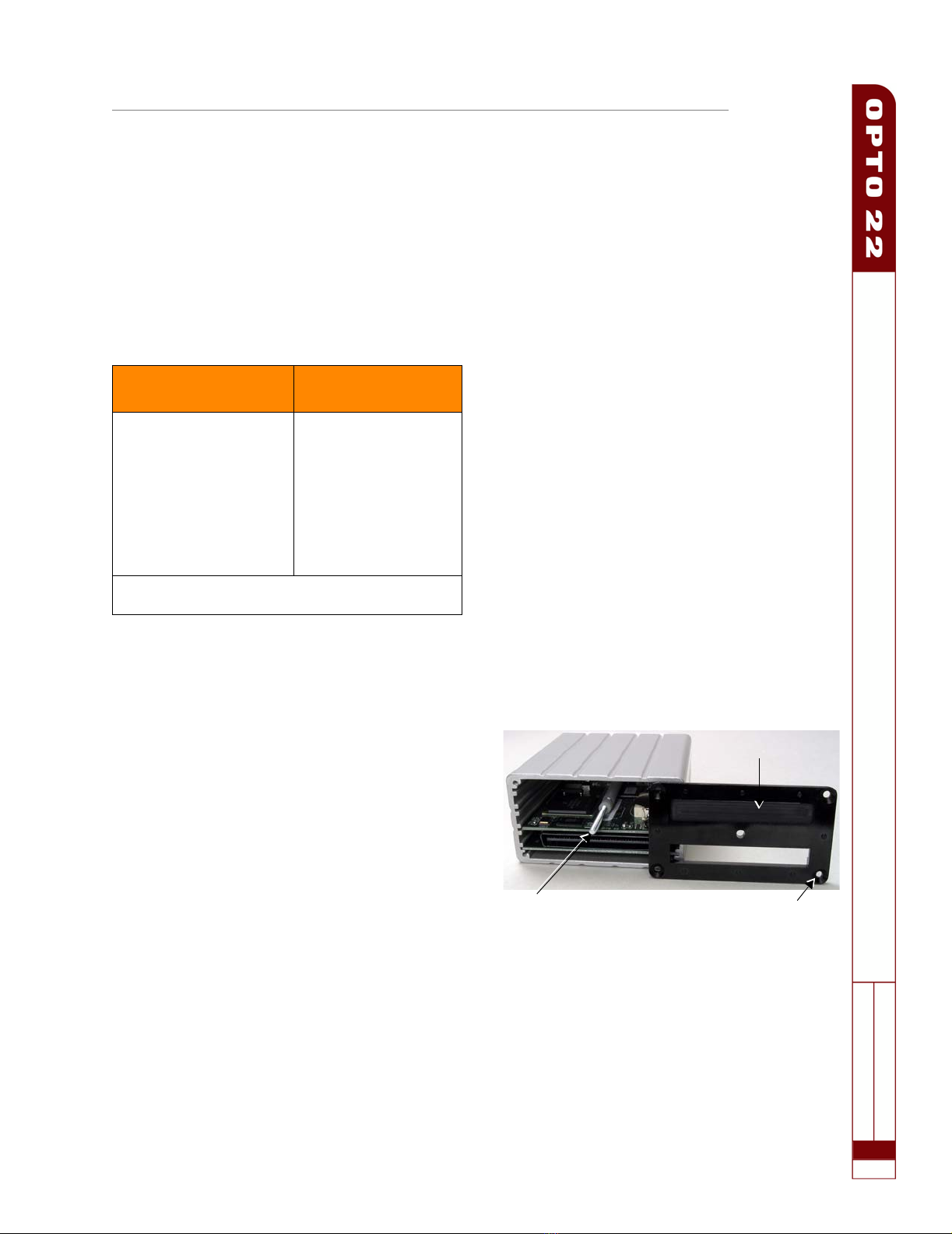
5. Hold the replacement baseplate so that its indentation is facing
away from the brain (see the following photo).
6. Align the brain’s hold-down screw with the center hole in the
replacement baseplate. Using the same four screws, attach the
replacement baseplate to the new processor.
7. On the rack, set the lock washer over the hole next to the pro-
cessor’s connector, and then screw the 6-32 hex standoff into
the hole. Tighten the standoff just to the position where two of
Install the adapter to use
one of these processors... ...on one of these racks
SNAP-PAC-R1
SNAP-PAC-R2
SNAP-PAC-EB1
SNAP-PAC-EB2
SNAP-B4M
SNAP-B8M
SNAP-B8MC
SNAP-B8MC-P
SNAP-B12M
SNAP-B12MC
SNAP-B12MC-P
SNAP-B16M
SNAP-B16MC
SNAP-B16MC-P
NOTE: The adapter can also be used with a SNAP-UP1-M64
or SNAP-ENET-S64 brain.
Indentation
Hold-down screw Beveled screw hole
(bevel faces out)
SNAP-RCK-M2B Rack Adapter Installation
Form 1695-080710 • Opto 22 • 43044 Business Park Drive • Temecula, CA 92590-3614 • www.opto22.com
SALES 800-321-6786 • 951-695-3000 • FAX 951-695-3095 • [email protected] • SUPPORT 800-835-6786 • 951-695-3080 • FAX 951-695-3017 • [email protected]
© 2007 Opto 22. All rights reserved. Dimensions and specifications are subject to change. Brand or product names used herein are trademarks or registered trademarks of their respective companies or organizations.
PAGE
2
the hex points are parallel with the connector, as shown in the fol-
lowing photo.
8. Holding the rack adapter with its part number visible on the top
and the blue connectors aligned underneath, set it in position on
the rack.
If it does not go on easily, make sure the hex nut’s points are prop-
erly aligned, parallel with the processor connector.
9. Align the new processor’s black connector with the mating con-
nector on the rack adapter, and make sure the indentation in the
baseplate aligns with the silver pins on the adapter.
The processor’s position is now reversed on the rack (that is, letters
on the processor’s lid are upside down).
10. Seat the processor onto the connector and use the hold-down
screw to secure the brain in position. Do not overtighten.
11. Replace cables and restore power to the rack.
If the new processor does not have an IP address, follow instructions in
the PAC Manager User’s Guide to assign it. Consult form #1688, the
SNAP PAC System Migration Technical Note, for important information
on using the new processor with the older rack.
For Help
If you have trouble installing or using the rack adapter and cannot find
the help you need in this document or on our website, contact
Opto 22 Product Support.
Opto 22 Product Support
Phone: 800-TEK-OPTO (835-6786)
951-695-3080
Monday through Friday, 7 a.m. to 5 p.m. Pacific Time
Fax: 951-695-3017
E-mail: support@opto22.com
Website: www.opto22.com
Two of the hex standoff’s points
must be parallel with the blue
processor connector.

Other OPTO 22 Adapter manuals

OPTO 22 SNAP-RCK-B2M User manual

OPTO 22

OPTO 22 SNAP-RCK-B2M User manual

OPTO 22 SNAP-RCK-B2M User manual

OPTO 22

OPTO 22 SNAP-RCK-B2M User manual

OPTO 22 SNAP-RCK-M2B Instruction Manual

OPTO 22

OPTO 22 SNAP-RCK-M2B Instruction Manual

Popular Adapter manuals by other brands

StarTech.com 115B-USBC-MULTIPORT quick start guide

StarTech.com

StarTech.com 115B-USBC-MULTIPORT quick start guide

Encore ENPWI-NX2 user guide

Encore

Encore ENPWI-NX2 user guide

SeaLevel SeaLINK+4.232 user manual

SeaLevel

SeaLevel SeaLINK+4.232 user manual

GFI System Interwire user manual

GFI System

GFI System Interwire user manual

Altronix eBridge1PCRMT installation guide

Altronix

Altronix eBridge1PCRMT installation guide

ABB FEPL-02 Ethernet POWERLINK user manual

ABB

ABB FEPL-02 Ethernet POWERLINK user manual

NEC N8104-157 installation guide

NEC

NEC N8104-157 installation guide

ZyXEL Communications G-220F user guide

ZyXEL Communications

ZyXEL Communications G-220F user guide

HTC VIVE user guide

HTC

HTC VIVE user guide

LM Technologies LM505 manual

LM Technologies

LM Technologies LM505 manual

TRENDnet TE-CF100 Specifications

TRENDnet

TRENDnet TE-CF100 Specifications

Abocom UHF1000 Specifications

Abocom

Abocom UHF1000 Specifications

TP-Link TL-WN727N user guide

TP-Link

TP-Link TL-WN727N user guide

D-Link DWA-131 Quick installation guide

D-Link

D-Link DWA-131 Quick installation guide

StarTech.com ICRS232BT1 instruction manual

StarTech.com

StarTech.com ICRS232BT1 instruction manual

Exsys EX-47960 user manual

Exsys

Exsys EX-47960 user manual

Broadcom Emulex LPe12000 Series installation guide

Broadcom

Broadcom Emulex LPe12000 Series installation guide

MEDIATEK MT7630E user manual

MEDIATEK

MEDIATEK MT7630E user manual

manuals.online logo
manuals.online logoBrands
  • About & Mission
  • Contact us
  • Privacy Policy
  • Terms and Conditions

Copyright 2025 Manuals.Online. All Rights Reserved.