User’s Guide
DRFA Ed 2018-1
AA OPTO-ELECTRONIC Tel: +33 (0)1 76 91 50 12
18, rue Nicolas Appert Fax: +33 (0)1 76 91 50 31
91898 ORSAY FRANCE www.aaoptoelectronic.com
AA Sa reserves the right to make changes to the products or information herein
without notice. No liability is assumed as a result of their use or application.
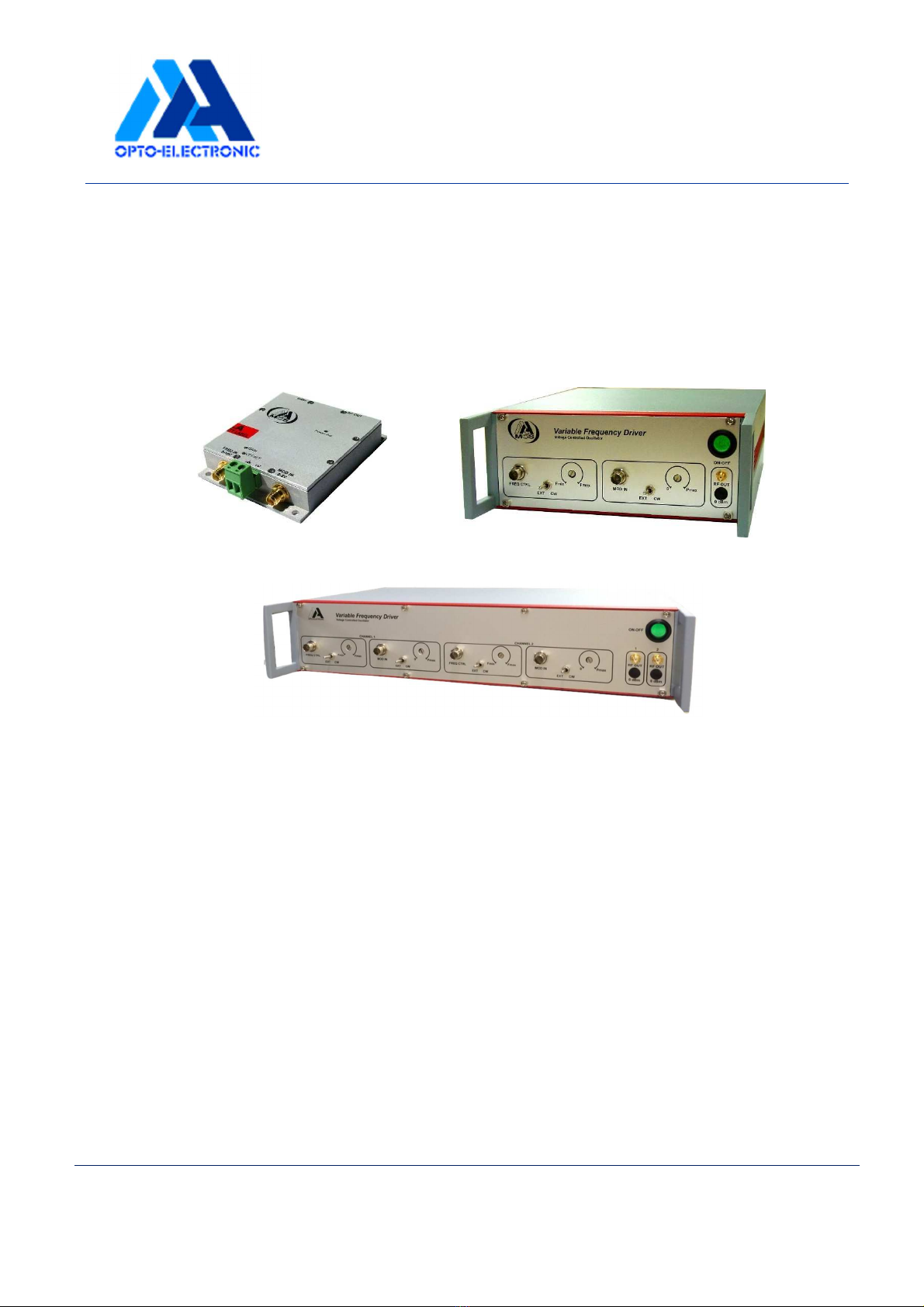
Connect the external modulation input « MOD IN » for AM control. Please refer to your test
sheet for exact signal amplitude and impedance.
Connect the external Frequency input « FREQ IN » for FM control. Please refer to your
test sheet for exact signal amplitude and impedance.
If the option is available, connect the external 0dBm output to an oscilloscope or frequency
meter. The level of this output will be constant (0dBm) and frequency will be simaly to the
RF output. It is used for frequency monitoring.
At this step we recommend to not touch the Gain and offset potentiometers.
Your driver is ready to operate. Switch ON power supply. Switch ON the AM and FM control
signals. We advise 15 minutes warm up to reach the best stability.
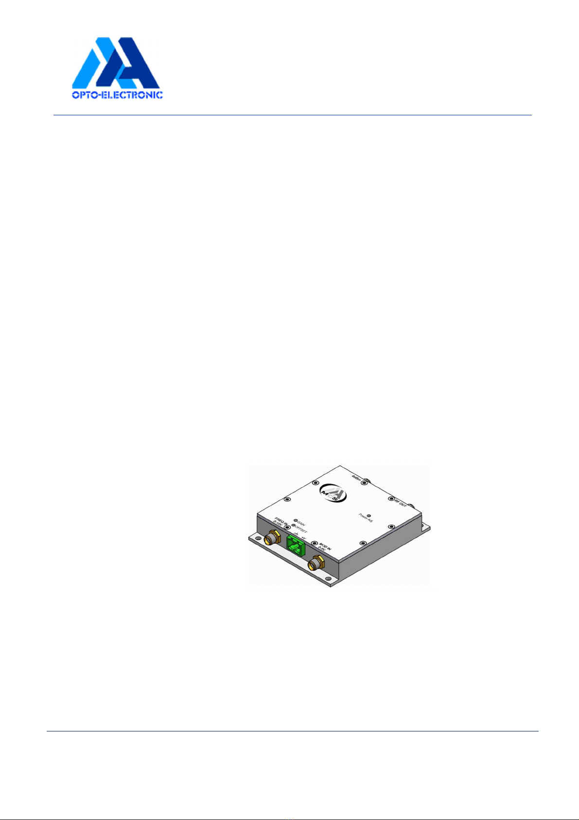
Maximum RF power level adjustment:
A screw potentiometer ("Power Adj.") is available to fully adjust the
maximum RF power level from 0 to a maximum value (see test sheet).
To adjust the maximum RF power level, your modulation input must be
active, with the maximum level (+5VDC for instance). At the contrary,
the output RF power of your driver will be only a fraction of the maximum
signal. For more information, refer to "Amplitude modulation" part.
With a screwdriver (2,2 mm large) :
- rotate the multi-turn potentiometer to clockwise to decrease RF power.
- rotate reverse side to increase RF power.
When monitoring the output signal from your driver, you will observe a sine wave, which
frequency is equal to the carrier frequency of your driver, and which amplitude is set via
the POWER ADJ.
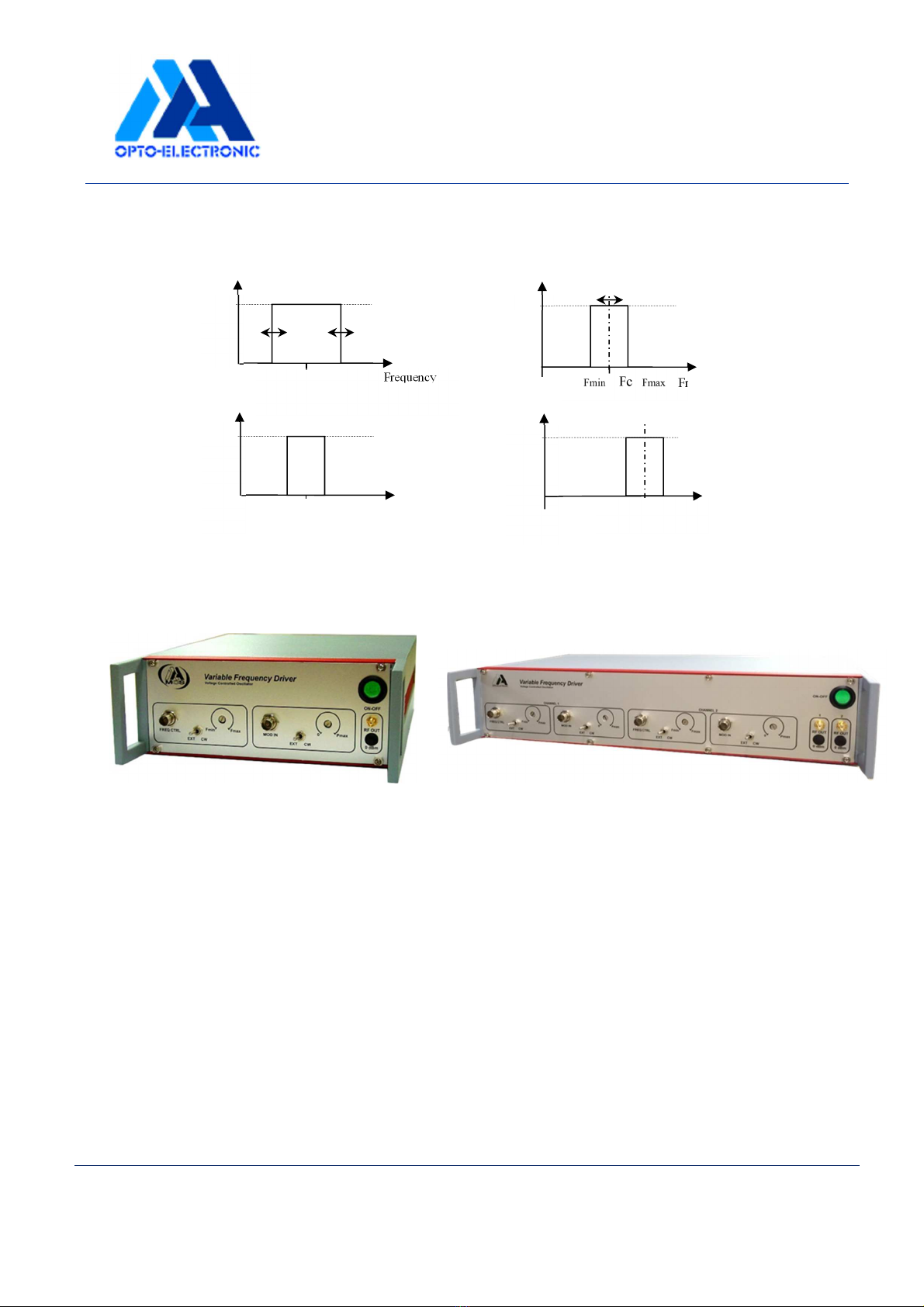
Frequency range adjustments: GAIN and OFFSET potentiometers
OEM drivers only:
The minimum and maximum frequencies are set at factory, and can
be slightly adjusted with potentiometers "OFFSET" and "GAIN".
With a screwdriver (2.2 mm large) :
- rotate the potentiometer "OFFSET" to adjust centre frequency Fc.
- rotate the potentiometer "GAIN" to adjust frequency range (Fmin-
Fmax) without modifying centre frequency.