Orban 424A User manual

422A/424AGated Gompressoi/
Limrtei/De-Esser
OPERATING MANUAL
orbon
adivision of AKG Acoustics, Inc.

422A/424AGated Gompressoi/
Limiter/De-Esser
OPERATING MANUAL
95028-000-05
erbon
adivision of AKG Acoustics, Inc.
645 Bryant St., San Francisco, California 94107 USA
Phone (415) 957-1067 Telex 17-1480 FAX (415) 957-1070
©1989, AKG Acoustics, Inc. 5/89-7P

GAIN REDUCTION:
Reads the gain of the VCA,
from 0to -25dB. Shows
the effect of any control
but OUTPUT TRIM and DE-
ESSER. v
r
INPUT ATTEN.:
Adjusts drive to compres-
sor/limiter, determining
amount of G/R.
-
ATTACK TIME:
Adjusts speed of response
to input level increase.
Fast: peak limiter &
compressor
Slow: compressor only
*•UN *’*
0-SHO>«-fO-?3
0»-«0-l9-tO-?S
GATE THRESH.:
Determines the input level
that causes “gating"; VCA
gain moves slowly to IDLE
GAIN control setting.
rrrfnn !gk\ ii 41 II
'im.’ w’ •'w ’Jmt
PAST UOW PAST UOW
INPUT ATTfN. COMM RATfO ATTACK TUMI Ml SHAPE REL. IIMI OATfO
«—
L
•.l‘I•tm <I*
nrfrn A-,’AV i|
’W’ •W’
Ulf irtMl Vat* wrr
•ii inr n
7010793 10
•mriTn
P/T tOW7BJ 10
'MAX
PAST UOW
DATED COMPREBBOR/LIMITER
OUTPUT TRIM:
Adjusts VCA gain to control
or prevent clipping; its ef-
fect is seen on VCA LEVEL
meter; not an output at-
tenuator (Output Attenuator
located on rear).
DE-ESSER OPERATE/
DEFEAT:
Activates or defeats de-
esser control circuitry.
|mo*m mvy
-4 *4 #OPI«AT«
-I (Of MAT
Jp. %
OUTPUT T»IM IDII GAIN COMP/LIM
-I (*1 4* -II- II _
-4 4k .4 •OPltAfl
Jt- A-W )DEMAT
JIt.Jp.
•OPMAH
OMMAT A
ins mow
•oriKAii jy
rDfMAT
%'w
ms
OE-EBBER
COUPLED/INDEP:
Couples Aand Bgain and
gating circuits for stereo
tracking.
•counro
0•NO**’
%
•ON
PIODBL 4B4A
COMPR. RATIO:
Adjusts compression from
“looser’’ (2:1) to
“tighter" (°°:1).
REL. SHAPE: Lin: com-
pressor releases at cons-
tant rate
Exp: release starts slower,
then speeds up
REL. TIME:
Adjusts speed of gain in-
VCA LEVEL:
Reads peak operating level
crease when output level is of VCA. Clipping occurs
below threshold of com-
pression.
above approximately
“+2”.
IDLE GAIN:
Determines VCA gain when
unit is gated (OPERATE
mode) or anytime unit is
DEFEATED.
OPERATE/DEFEAT:
Activates or defeats comp/
lim control circuitry. Does
not bypass any circuitry.
DE-ESSER SENSITIVITY:
Adjusts threshold of de-
essing.
CAUTION
OPELECTRICAL SHOCK
DO NOT PEWOVn COVER. NO USER
SERVICEABLE PARTS INSIDE
REFER SERVICING TO QUALIFIED
SERVICE PERSONNEL Hi
^WARNING
TO REDUCE THE RISK Of FIRE
O* fLFCTUK At SHOCK DO N» f
EXPOSE THIS APPLIANCE TO
BAIN OR MOISTURE
-OR CONTINUED
PROTECTION AG»'N«,t
FtWE HAZARD RfPlACf
ONLY WITH SAME TYPE
FUSE SAC, S/S
FOR 115V MAINS I/4A
FOR JJOV MAINS I/I A
®Sr ?9S9 9 39 9
99999999999*9
MODEL 424A SHOWN

Table of Contents
About This Manual
Registration Card
Warranty
ICondensed Operating Instructions
5Part A: Introduction
5Performance Highlights
6Front-Panel Description
6Rear-Panel Description
7Part B: Installation
7
Mechanical Installation
7Electrical Installation
AC Power
Control Loop Bass Rolloff
Audio
Output
Preferred Wiring
Table I: General Input/Output Connection Rules
Wiring The 424A With Single-Conductor Shielded
Cable
1 1 Part C: Operating Instructions
II Description and Function of Front-Panel Features
Using The Compressor/Limiter
Using The De-Esser
Adjusting The OUTPUT ATTEN Control
19 Some Specific Applications
Adjusting The 424A To Provide Peak Overload
Protection
Stereo And Multichannel Operation
Speech-Activated Ducking Of Music
21 Part D: Maintenance
21 Introduction
21 ALIGNMENT AND PERFORMANCE VERIFICATION
General
Power Supply
Signal Processing Circuitry
27 MAINTENANCE AND SERVICE
Preventive Maintenance
Corrective Maintenance
Service Access
Lamp Replacement
Component Replacement
Replacement Parts
Replacement Of Components On Printed Circuit
Boards
Removal
Installation
Troubleshooting 1C Opamps
Factory Service
Shipping Instructions
31 CIRCUIT DESCRIPTION
General
Input Buffer
Voltage-Controlled Amplifier (VCA) Operation
Current-Controlled Gain
Exponential Converter
Compressor/Limiter Circuitry
General
Rectifier With Threshold
Timing Module
Threshold-Setting Circuitry and RATIO Control
Gating Circuitry
Gain Reduction Meter
De-Esser Control Circuitry
VCA LEVEL Meter
Power Supply
40 APPENDIX A: INTERCONNECTIONS AND GROUNDING
43 APPENDIX B: SPECIFICATIONS
44 PARTS LIST
53 SCHEMATIC
54 PARTS LOCATOR

ABOUT
THIS MANUAL
REGISTRATION
CARD
WARRANTY
Except for the first few sections, the information contained in this manual is
primarily for reference and to aid maintenance. The unit has been designed to be
straightforward and intuitive to use, and most experienced compressor/limiter users
will be able to use it easily without instruction.
However, anumber of subtle features have been included. Full understanding of
these will enable anyone —beginner or pro —to get the most of the unit. Time
spent with the manual will often yield substantial rewards.
The original purchaser should have received apostpaid Registration Card packed
with this manual.
Registration is of benefit to you because it enables us to tell you of new
applications, possible performance improvements, service aids, etc., which may be
developed over the life of the product. It also provides us with the date of sale so
that we may more promptly respond to possible claims under Warranty in the
future (without having to request acopy of your Bill of Sale or other proof of
purchase).
Please fill in the Registration Card and return it to us.
If the Registration Card has become lost or you have purchased the unit used,
please photocopy the image of the card reproduced below and send it to us in an
envelope. Use the address shown on the title page.
Model #Serial #
Name or Title
Organization
Street
City/State/Country
Zip or Mail Code
Purchased from City Date of Purchase
Nature of your application
How did you hear about it?
Comments:
Fig. A- 1:REGISTRATION CARD
The Warranty, which applies only to the first end-user of record, is stated on the
Warranty Certificate on aseparate sheet packed with this manual. Save it for
future reference.
Details on obtaining factory service are provided in Part D.

Condensed Operating Instructions
These instructions are primarily designed to help you get started using your
422A/424A. (The later parts of your OPERATING MANUAL contain much more
detail, and will help you get the most from your 422A/424A after you have
become familiar with the basics.)
Operationally, the 422A/424A can be considered to be abasic compressor/li miter
with enhancements. If you are just beginning to learn about it, or if you only need
basic compressor functions, you needn't worry about these enhancements.
Most of the enhancements are associated with the Gating function. If the GATE
THRESHold control is turned OFF (fully counterclockwise), these enhancements are
not operative and need not concern you now.
To Use The Compressor/Limiter: Preset the following controls:
REL SHAPE
GATE THRESH
OUTPUT TRIM
IDLE GAIN
COMP/LIMITER OPERATE/DEFEAT
DE-ESSER OPERATE/DEFEAT
LIN
OFF
0(at the detent)
0
OPERATE
DEFEAT
You then need to deal with only four familiar controls: INPUT ATTENuator,
RATIO, ATTACK TIME, and RELEASE TIME. These controls are always adjusted by
ear to obtain the desired sound. If you have used any common professional
compressor or limiter before, these controls should operate intuitively:
I) Adjust the INPUT ATTENuator control until the GAIN REDUCTION (G/R)
meter indicates the desired amount of G/R. Don't let the G/R meter enter the
red section of the scale.
2)
Adjust the RATIO control to determine if compression will be "tight" or
"loose". "Tight" means that alarge increase in input level will produce asmall
increase in output level. As the ratio becomes "looser", the output level will
change more and more for agiven change in input level. 2:1 is the "loosest"
ratio; infinity: Iis the "tightest". "Looser" ratios tend to give more natural,
dynamic sound at the expense of lower loudness and less consistent levels.
(Adjusting the RATIO control to "looser" settings automatically lowers the
compression threshold to prevent peak overload of the 422A/424A circuitry or
of the device being driven by the 422A/424A when high amounts of gain
reduction are used.)
3)
Adjust the ATTACK TIME control to determine how quickly the 422A/424A
responds to an input level increase. Fast attack times produce the most
consistent control of peak levels (and therefore produce highest loudness).
However, their effect tends to be more audible than that of slow attack times.
Slow attack times permit transient material to pass through the 422A/424A
unaffected, so that transient definition is retained.
(To prevent transient overshoots permitted by slow attack times from
overloading either the 422A/424A circuitry or devices being driven by the
422A/424A, the threshold of compression is reduced as the attack time is made
slower. This way, the peak level at the output remains approximately constant
as the ATTACK TIME control is adjusted.)

The ATTACK TIME control is calibrated with an arbitrary scale because the
attack time is automatically varied according to the nature of the program
material. This minimizes audible compression-induced side-effects.
Because the range of the ATTACK TIME control has purposely been made very
wide, certain sounds can cause the 422A/424A to produce distortion when
operated with fast attack times. Such sounds include certain male voices,
Hammond organ, and some types of bass (particularly synthesizer-produced). Such
distortion can be totally eliminated by operating with slower attack times —
usually between "5" and "SLOW" on the dial.
4) Adjust the RELEASE TIME control to determine how fast the 422A/424A gain
recovers toward maximum during those times when its output level is below the
threshold of compression.
Fast release times produce the greatest "density" and most consistent output
levels. However, they also create the greatest risk of audible side-effects. They
are most useful in recording studios or production situations where the program
material being processed is asingle track and is to be mixed with other
material.
Slower release times generally produce amore natural sound on mixed program
material. Accordingly, they are more useful in such applications as broadcast
production or cassette duplication.
The RELEASE TIME control is calibrated with an arbitrary scale because the
release time is automatically varied according to the nature of the program
material. This minimizes audible compression-induced side-effects.
(The RELease SHAPE switch determines if the release proceeds at aconstant
number of dB per second (LINear), or if it starts more slowly and then speeds
up as it progresses (EXPonential). LINear usually sounds most natural, but
EXPonential can be useful if you want to create the "open" sound associated
with slow release times, yet gain-ride quickly during pauses or low-level program
material. Like the other controls, it should be adjusted "by ear" to your taste.)
5) It is important to note that the OUTPUT TRIM control should not be treated
like afamiliar "output attenuator" control: It is ordinarily left at "0". Its
purpose is to permit you to operate the Voltage-Controlled Amplifier (VCA) in
the optimum part of its range for your application. You can use the OUTPUT
TRIM control to create controlled clipping in the VCA, to prevent VCA clipping,
or to optimize the signal-to-noise ratio. Refer to the OF*ERATING MANUAL for
further details.)
Astandard OUTPUT ATTENuator control is located on the rear panel.
Compressor/Limiter Enhancements: The IDLE GAIN control determines the gain of
the Compressor/Limiter when the COMP/LIM OPERATE/DEFEAT switch is in
DEFEAT. If the IDLE GAIN control is set close to the average amount of gain
reduction, the Compressor/Limiter can be defeated and reactivated in the middle
of program material without obvious side-effects such as sudden gain changes. (The
control also has asecond function which will be explained below.)
2

The gating features permit the 422A/424A to handle noise or low-level program
material differently than it handles high-level program material. The gating feature
is not the same as aconventional "noise gate": It is not intended to reduce noise
or other undesired sounds below the level at which they exist in the original
program. Its purpose is to prevent compression from unnaturally exaggerating such
material. If needed, aconventional noise gate can be used before the 422A/424A.
The gating feature is activated whenever the GATED lamp is on. This lamp will
turn on whenever the input level drops below athreshold set with the GATE
THRESHold control. (In its OFF postion, this control totally defeats the gating
feature.)
When the GATED lamp is on, the gain of the Compressor/Limiter moves slowly to
apoint set by the IDLE GAIN control. This gain change is indicated on the GAIN
REDUCTION meter. If the IDLE GAIN control is set at apoint equal to the
average amount of gain reduction occurring, then gain will neither increase nor
decrease during low-level program materal or pauses. In particular, noise will not
be "pumped up" as in aconventional compressor. For example, if you are
compressing aparticular track in amultitrack mixdown, tape hiss or low-level
material below the gating threshold will not be increased in level at the beginning
of the mix (before high-level program material first appears on the track), or
during pauses in the track.
If the IDLE GAIN control is set lower than the average gain reduction, then it
can leave a"hole" when high-level program material reappears and turns the
GATED lamp off. This is because the Compressor/Limiter must recover to ahigher
gain to produce full loudness, and this cannot happen instantaneously: The time
necessary for recovery is determined by the RELEASE TIME control.
To Use The De-esser: To use the De-esser, switch the DE-ESSER
OPERATE/DEFEAT switch to OPERATE and adjust the De-esser SENSITIVITY
control until "esses" sound naturally balanced with the rest of the voice.
The threshold of de-essing is fixed by the SENSITIVITY control, and does not track
the average vocal level (as in the Orban dedicated de-essers). For consistent de-
essing, it is important that the level presented to the De-esser be relatively
constant. This is ordinarily achieved by compressing the voice with the
Compressor/Limiter, which is functionally ahead of the De-esser.
It is sometimes possible to de-ess vocals which have been mixed with other
material. Each case must be evaluated by ear. The DE-ESSER OPERATE/DEFEAT
switch does not introduce clicks, pops, or discontinuities into the program, so the
De-esser can be keyed in or out in the middle of program material as required.
This may be the best way to handle afew problem "esses" in mixed program
material.
3

PERFORMANCE
HIGHLIGHTS
Part A: Introduction
The Orban Model 422A/424A Compressor/Limiter/De-Esser is an integrated AGC
device of highest professional quality. It can perform compression, peak limiting,
and vocal de-essing functions simultaneously with unusual freedom from side-effects.
It can thus serve either as ageneral-purpose no-compromise compressor/limiter, or
as acomplete dynamic processor for conditioning vocals. However, it is not
optimized for over modulation protection of broadcast transmitters, and the Orban
OPTIMOD-AM, -FM, or -TV should be used in such applications.
The flexibility and natural sound of the 422A/424A make it applicable in other
areas of professional audio as well: recording studios, sound reinforcement, public
address, motion picture sound, etc.
The product is available in both single- (422A) and dual- (424A) channel versions.
(For clarity, only the 424A will be referenced in this manual.) The dual-channel
version is equipped with acoupling switch which forces the gain of both channels
to be equal, tracking the channel demanding the greatest amount of gain reduction.
This preserves correct imaging in stereo applications. However, the stereo coupling
switch does not couple the operating controls, and these are ordinarily set
identically in stereo operation.
Attack and release times are both program-controlled, but can be scaled faster or
slower by means of front-panel controls. This results in maximum flexibility, plus
extremely natural sound over awide range of control settings.
The 424A Compressor is equipped with electronically-balanced inputs and outputs
and is compatible with the levels and impedances found in both professional and
semi-professional applications. RF suppression applied to the input, output, and
power leads enables use in relatively high RFI fields such as those common in
broadcasting.
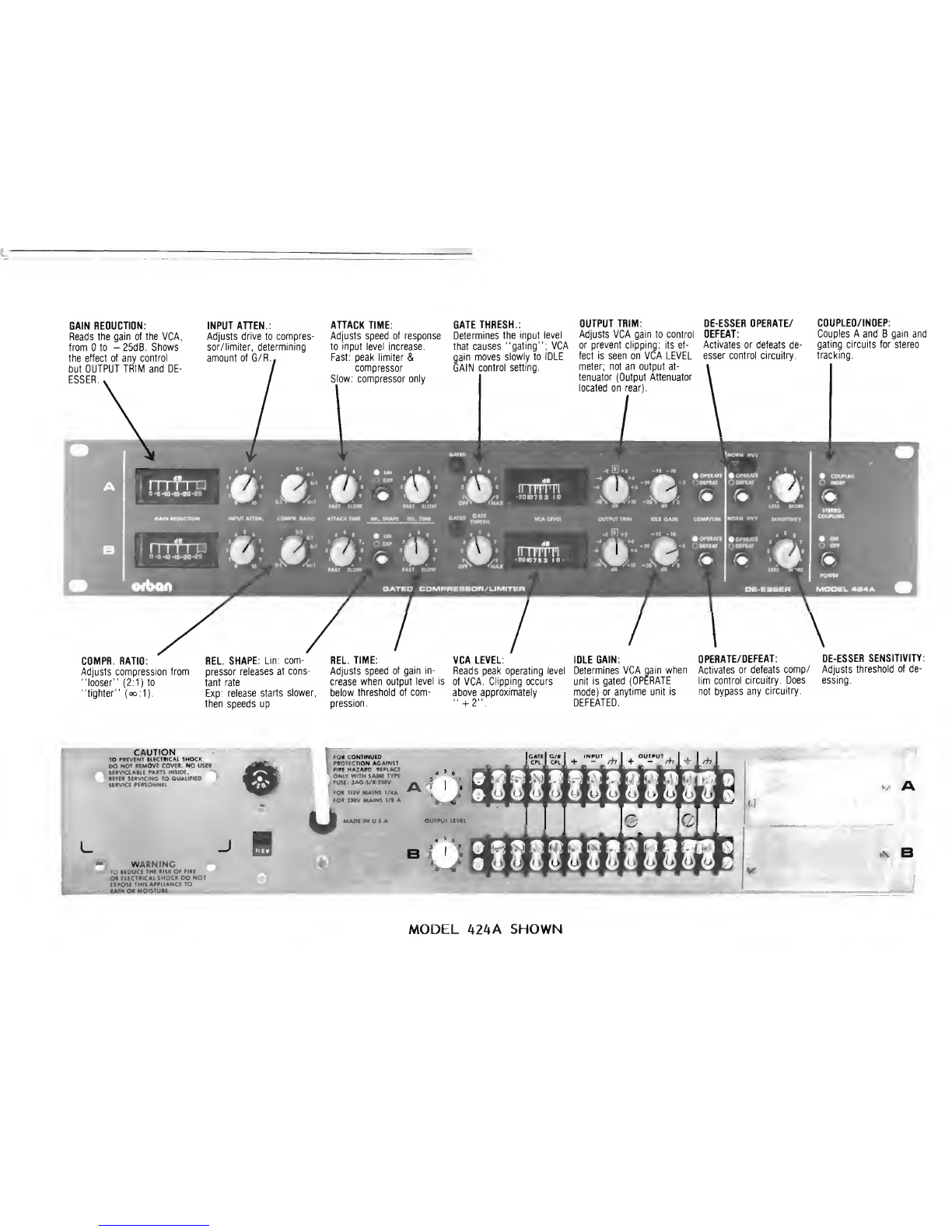
The controls and features of the 424A Compressor are fully described in this
manual. It will familiarize you with the unit's potential and enable you to
imaginatively use the 424A for your specific installation and application.
Because the front-panel controls are marked in afamiliar way, you may be
tempted to jump right in without reading the manual. However, if you take the
time to review the Description And Function Of Front-Panel Controls and
Operating Instructions in Part C, you will find that there is "more than meets the
eye" inside the 424A, and that the time you take reading the manual will be well-
rewarded by agreater understanding of the unit's potential.
Production AGC function using circuitry adapted from industry-standard
OPTIMOD-FM Model 8I00A broadcast signal processor
De-esser characteristics similar to highly-accepted Orban dedicated de-essers
Independent compressor/limiter and de-esser control loops with optimized,
program-controlled parameters for each
Unbeatable ability to increase average loudness of program material or
individual tracks without introducing unnatural sound quality or artifacts
Defeatable gain-freezing gate with user-adjustable threshold to prevent
pumping and breathing during pauses
5

Wide-range attack time,release time,and ratio controls permit device to
sound extremely natural or to create special effects
Extremely easy to use because attack and release time controls interact and
also change the compression threshold, assuring consistent peak output levels
and minimizing need for manual readjustment of the output attenuator
Operation is intuitive and natural -- you don't need achart or an advanced
degree to figure out what's happening
Low-distortion operation teams clean class-A VCA with all-important dynamic
distortion reduction in the control circuitry
—25dB gain reduction range with constant 90dB (typical) clip-to-noise ratio
regardless of amount of gain reduction
Better than 25dB de-ess gain reduction available in addition to the 25db
compressor/limiter gain reduction
—True peak-reading output level meter allows operator to positively prevent
VCA clipping —or to use acontrolled amount of clipping to limit peak levels
—True peak-reading gain reduction meter
—Choice of general-purpose linear or special-purpose exponential release
characteristics
—Strong all-metal 19" rack mount package for ruggedness, roadworthiness, RFI
shielding, and ease of mounting
—Lighted meters with long-life lamps
Input, output, and AC power RFI suppression make the unit ideal for difficult
environments like broadcast stations, areas near mobile communications
transmitters, etc.
—Balanced inputs and outputs
—II5/230V 50/60Hz power supply standard
—Industrial-grade parts and construction
—Highly cost-effective
FRONT PANEL The Front-Panel Photograph at the beginning of this Manual shows the various
DESCRIPTION operating controls. These controls and their operation are fully described in
Description and Function of Front Panel Features in Part C(Operating
Instructions) below.
REAR PANEL The FUSE used in both the 422A and the 424A is aI/4A (115 volt operation) or
DESCRIPTION I/8A (230 volt operation) 3AG 250V SLO-BLO type. Replace with the same type
only.
The OUTPUT ATTENUATOR is fully described in Description and Function of
Front Panel Features in Part C(Operating Instructions) below.
The INPUT and OUTPUT connectors provided allow connection via barrier strip (#5
screw). Holes are provided for installation of "XLR"-type connectors, and aretrofit
kit is available from your dealer.
Please refer to the Electrical Installation section for connection instructions.
6

Part B: Installation
MECHANICAL Vertical space of two standard rack units (3 l/2"/8.9cm) is required for either the
INSTALLATION 422A or the 424A.
Mounting the unit directly over large heat-producing devices like avacuum-tube power
amplifier may shorten component life and is not recommended. Ambient temperature
should not exceed II3°F (45°C) when equipment is powered.
ELECTRICAL AC Power
INSTALLATION The power transformer can be connected for 115 volt or 230 volt 50 or 60Hz AC
operation by means of aselector switch on the rear panel.
TYPE 18/3 SVT CORD, TYR-.
(3 x.82 mm*)
CONDUCTOR WIRE COLOR
Normal Alt
LLINE BROWN BLACK
NNEUTRAL BLUE WHITE
EEARTH GND GREEN-YELLOW GREEN
Fig. B-l: AC MAINS LINE CORD DETAIL
WARNING!
THE GROUND (EARTH) PIN ON THE PLUG SERVES TO RELIABLY
GROUND THE CHASSIS WHEN CONNECTED TO ASUITABLY GROUNDED
RECEPTACLE. IF THE GROUND MUST BE DEFEATED FOR HUM OR
NOISE REDUCTION, SECURELY CONNECT THE CHASSIS TO A
RELIABLE EARTH GROUND TO MAINTAIN PROTECTION FROM
ELECTRICAL SHOCK CAUSED BY ANY FAULT WHICH COULD CAUSE
THE CHASSIS TO BECOME DANGEROUSLY CHARGED.
Control Loop Bass Rolloff
The compressor/limiter control loop is ordinarily operated with abass rolloff
which simulates the response of the ear and results in amore natural sound.
However, certain applications demand that the 424A perform an accurate peak
limiting function. This requires a"flat" response from the control loop.
The bass rolloff network can be jumpered out on the circuit board(s) inside the
424A. Each unit is shipped with the jumpers in the "rolloff" position. To restrap to
the "flat" position, move the jumpers according to Fig. B-2, following the User
Access instructions in Part D.
7

EEFF.AT IE ROLLOFF CJUMPER.
LF R0U.OFF
[o]o CEFtATEO
Audio
Connecting the 424A Compressor to other equipment is quite straightforward.
Relatively uncomplicated systems (such as home playback systems, "semi-pro"
recording studios, electronic music studios, dance bars, etc.) tend to come together
without serious grounding problems even if the wiring practices are somewhat
casual, provided that high RF fields are not present. Unusual situations can be
analyzed if you are familiar with the standard rules governing grounding and
interfacing between balanced and unbalanced systems.
The instructions below will apply to the majority of cases. Acomprehensive
discussion of interconnections and grounding can be found in Appendix A.
Input: The electronically-balanced input of each channel of the 424A Compressor
is compatible with most professional and semi-professional sound equipment,
balanced or unbalanced, whose source impedance is 600 ohms or less. If it is
greater (as in some vacuum-tube audiophile preamps), aminor modification may be
made to the input to accomodate the situation. Please refer to Appendix Afor
further details.
Nominal input level is between -10 and +4dBm. The absolute overload point is
+20dBm.
Output: The two outputs of each channel of the 424A are electronically-balanced
to ground. The source impedance of each leg is 47 ohms in parallel with lOOOpF to
the chassis (for RFI suppression). Each output is capable of driving loads of 600
ohms or higher.
If an unbalanced output is required (to drive unbalanced inputs of other
equipment), it should be taken between the (+) output and circuit ground.DO NOT
GROUND THE (-) OUTPUT. While no immediate damage will result, this will short
the output of the (-) amplifier to ground through a47 ohm resistor, significantly
stressing the output amplifier 1C and possibly shortening its life due to thermal
cycling.
Preferred Wiring: We recommend wiring with two-conductor shielded cable (such
as Belden 8451 or equivalent) because signal current flows through the two
conductors only. The shield does not carry signal, is used only for shielding, and is
ordinarily connected to ground at one end only. The following table and diagram
are applicable to agreat majority of installations.
If you wish to use single-conductor shielded cable, see the section immediately
below. Q

Fig. 8-3: GROUNDING SCHEMES
GENERAL INPUT/OUTPUT CONNECTION RULES
INPUT
1) Always use "+" and as the two input terminals to the 424A.
2) When the 424A is driven from an unbalanced source, connect shield both
to circuit ground of source, and to chassis ground of 424A.
3) When the 424A is driven from abalanced source, connect shield at source
end to chassis ground. Do not connect shield at 424A end.
OUTPUT
1) On the 424A output, connect shield at 424A end to chassis ground
(whether driving balanced or unbalanced). Do not connect shield at other
end.
2) When driving abalanced load, jumper circuit ground to chassis ground on
424A (on rear panel). When driving an unbalanced load, do not attach
jumper.
3) When driving an unbalanced load, connect the the input ground of the
driven equipment to the 424A's circuit ground (not to the 424A's (-)
output). Connect the hot side of the driven equipment's input to the 424A's
(+) output.
9

GENERAL
I) 424A chassis should always be earth-grounded (i.e. through third wire
in power cord or through rack.) for maximum protection from shock.
Floaf this ground only as last resort.
Because it is not always possible to determine if the equipment driving or being
driven by the 424A has its circuit ground internally connected to its chassis ground
(which is always connected to the ground prong of the AC line cord, if present),
and because the use of fhe AC power line ground often introduces noise or other
imperfections such as RFI, hum, clicks, and buzzes, the wiring techniques in the
diagram are not universally applicable.
If you follow the diagram and hum or noise appears, don't be afraid to
experiment. If the noise sounds like alow-level crackling buzz, then probably there
isn't enough grounding. Try connecting the input of the 424A to achassis
ground terminal on the barrier strip and see if the buzz goes away. You can also
try strapping the 424A's chassis and circuit grounds together, and see if this helps.
Aground loop usually causes asmooth, steady hum rather than acrackly buzz. If
you have aground loop, you can often break it by disconnecting the jumper
between circuit and chassis grounds on the 424A's rear-panel barrier strip. In either
case, think carefully about what is going on, and keep in mind the general
principle: one and only one circuit ground path should exist between each piece of
equipment! (Bear in mind that the circuit grounds of the two channels of the 424A
dual-channel unit are connected together internally, and could conceivably introduce
aground loop if you do not take this connection into account in planning your
wiring.)
Wiring The 424A With Single-Conductor Shielded Cable: Sometimes, particularly if
you are using the 424A with musical instruments or home-type equipment, single-
conductor shielded cable may be the only type immediately available, making it
impractical to use the preferred two-conductor cable. In this case, connect the
inner conductors of the shielded cables to the "+" sides of the 424A inputs and
outputs. Connect the shield of the 424A input cable to the input, and connect
the shield of the 424A output cable to the 424A circuit ground terminal on the
rear-panel barrier strip.
The shield will ordinarily receive chassis ground from the external equipment
which it is connecting to the output of the 424A. The chassis ground/circuit ground
jumper on the rear barrier strip of the 424A should be left in whichever
configuration gives minimum hum or buzz. To minimize hum or buzz, it may be
necessary to jumper one or more shields to chassis ground. Because use of single-
conductor cables virtually eliminates any possibility of carefully controlling the
system grounding scheme, it is NOT RECOMMENDED! Even so, it often does work
adequately.
10

Part C: Operating Instructions
FRONT PANEL While the following control descriptions might seem unnecessarily complex on first
DESCRIPTION reading, they have been crafted to answer any reasonable question either the
AND FUNCTION beginner or the experienced user might ask. The effects of, and interactions
between, the controls have been designed to promote ease of use, facilitafing good
results with minimum effort. Some of these interactions and effects are subtle, and
are much more easily appreciated by actual practice than by reading.
Refer to the Front-Panel Photograph at the beginning of this Manual.
The GAIN REDUCTION meter is electronically conditioned to show the true
peak gain reduction of fhe compressor/limiter section, in dB. It does not
indicate the amount of de-essing gain reduction, which is indicated by
illumination of the NORMal and HEAVY de-essing indicators.
If the meter enters the red part of the scale, it indicates that no further
gain reduction is available in the compressor/limiter section, and that audible
"gulping" or other peculiarities caused by the control loop's saturating are
imminent.
The INPUT ATTENuator adjusts the drive level to the compressor/limiter,
thus determining the amount of gain reduction. (NOTE: There Is no user-
adjustable THRESHOLD control. However, adjusting either the ATTACK TIME
or RATIO controls also adjusts the threshold to keep the peak output level
approximately constant.)
The COMPression RATIO control adjusts the compression ratio (i.e., the dB
change in input level divided by the resultant dB change in output level). The
calibrations are only valid at the threshold of gain reduction. As more gain
reduction is used, the compression ratio increases, yielding a"soft knee" curve
when the COMPression RATIO control is adjusted for lower ratios.
Fig. C-l: OUTPUT LEVEL AS AFUNCTION OF INPUT LEVEL
FOR VARIOUS SETTINGS OF THE RATIO CONTROL
The ATTACK IIME control scales the program-controlled attack characteristic
faster or slower, and simultaneously adjusts the compression threshold. (The
attack time is not constant.)

At faster ATTACK TIME settings, substantial peak limiting action is produced
with typical program material. As the ATTACK TIME is slowed, the 424A acts
more and more like apure compressor, and fast peaks are permitted to
overshoot more and more.
Because overshoots tend to increase, the compression threshold is
automatically lowered as the attack time is slowed to avoid clipping the
Voltage-Controlled Amplifier (VCA) used as the gain-control element. At the
very slowest attack times, the release time is also lengthened by afactor of
approximately 4:1 to assure that the 424A is working in atruly "averaging"
mode at these very slow attack times, and that the attack time does not get
slower than the release time.
The RELEASE TIME control 'scales the program-controlled release
characteristic faster and slower. (The release time is not constant; it is varied
according to the previous history of the program dynamics.)
To avoid having fast transients punch "holes" in the program material, the
release rate is automatically speeded up after alarge change in gain reduction.
This creates afast "peak limiting" function which rides on top of amuch
slower "compression" function. It is the recovery rate of the "compression"
function which is affected by the RELEASE TIME control.
The RELEASE SHAPE switch further modifies the action of the RELEASE
TIME control. It determines if the recovery rate (in dB/second) of the
"compression" function is constant (LINear mode), or if it starts out slowly,
and then speeds up as it goes along (Exponential mode), as in Fig. C-2. (The
fast limiting recovery is unaffected by the RELEASE SHAPE switch.)
The LINear mode almost always sounds more natural.
OdB
VCA
GAIN
-20dB
TIME —
>
Fig. C-2: LINear VERSUS Exponential RELEASE SHAPES
While the initial release rate (dB/sec) in EXPonential mode is approximately
three times slower than in LINear mode for a given setting of the RELEASE
TIME control, with large amounts of gain reduction it becomes approximately
three times faster than LINear mode by the time the compressor has fully
recovered.
12

The Exponential mode is useful when the 424A is used to ride gain on wide
dynamic-range program material (such as certain vocalists), yet avery "open"
sound (associated with slow release times) is desired.
The GATE THRESHold control determines the input level at which the
compressor release process becomes "gated". When this happens, the compressor
gain "freezes" wherever it happens to be, then immediately starts slowly
drifting to apoint pre-determined by the setting of the IDLE GAIN control
(see below).
The fast limiting release process is unaffected.
Under this condition, the GATED lamp is lit.
The gating function can be used to prevent noise "pump-up" or "breathing"
during pauses and/or to control hiss from empty tracks at the beginning of a
mix. Aconventional non-gated compressor would recover to full gain, increasing
noise levels.
This function is not the same as the familiar "noise gate" or "expansion"
function. If further noise reduction is desired, aconventional full-featured noise
gate can be used ahead of the 424A. However, if the 424A's IDLE GAIN
control is set to match the average amount of gain reduction, more subtle
processing than that produced by a noise gate is achieved since noise will
neither increase nor decrease during pauses.
The gating function is defeatable by turning the GATE THRESHold control
fully counterclockwise. In asense, the gating function is the opposite of the
Exponential release function, in that the gating function slows and redirects
the release characteristic during pauses, while the Exponential function speeds
up the release process. However, the gating function can still be operated when
in the EXPonential release time mode, and it is possible that the two functions
may complement each other in certain applications. Only experimentation can
tell!
The VCA LEVEL meter indicates the peak output level of the 424A
compressor/limiter voltage-controlled amplifier (VCA). Ordinarily, if will
unambiguously indicate VCA clipping, which occurs at approximately "+3dB" on
the meter.
The meter accurately captures and holds the peak level of even the fastest
program peaks, and will read within 0.5dB of fhe frue peak value of a10
microsecond pulse.
However, it is possible that VCA clipping will not be identified if high-energy,
high-frequency program material is processed by both the compressor/limiter
and de-esser sections simultaneously. In this case, clipping may occur in the
compressor/limiter section of the VCA, yet the de-esser section of the VCA
may reduce the final VCA output level as observed on the VCA LEVEL meter
such that clipping is not indicated. (Ordinarily, amoderate amount of clipping
of program material of this type is not audibly offensive.)
The OUTPUT TRIM control is again control used to control or to prevent
clipping in the VCA. IT IS NOT ACONVENTIONAL OUTPUT ATTENUATOR
CONTROL, AND MUST NOT BE USED AS SUCH, LEST THE VCA BE
OPERATED IN ANON-OPTIMUM PART OF ITS GAIN CONTROL RANGE!
13

The performance of the VCA used in the 424A is optimized with regard to
noise and distortion over a25dB gain reduction range. When the OUTPUT TRIM
control is on the "0" detent, it guarantees that the VCA will be operated in
the optimum part of its range regardless of the amount of gain reduction as
indicated on the GAIN REDUCTION meter.
Turning down the OUTPUT TRIM control simultaneously lowers the VCA gain
and the compression threshold so that the gain reduction remains approximately
constant. At the same time, the amount of available gain reduction is reduced.
For example, if the OUTPUT TRIM control is set to "-5dB", then the maximum
available gain reduction is 20dB, instead of 25dB.
Certain very "spiky" program material will tend to overshoot more than
average program material, thus partially foiling the automatic adjustment of
compression threshold as ATTACK and/or RATIO controls are operated (as
described above). These excessive overshoots (which are clearly indicated on the
true peak-reading VCA LEVEL meter) can clip the VCA unless the OUTPUT
TRIM control is turned down.
If you wish to obtain amore natural sound than that produced by very fast
attack times in applications where the absolute peak levels are important (such
as overmodulation protection of abroadcast studio-transmitter link or disk
cutter protection), this improved naturalness can often be achieved by operating
with slower attack times and clipping off the higher-amplitude overshoots in
the VCA. This can be done by advancing the OUTPUT TRIM control until the
desired amount of clipping is observed.
You will find that turning the control u£ usually does not result in output
level increases proportional to those calibrated on the dial, and also results in
increased gain reduction. This is because the 424A contains circuitry which
automatically speeds up the attack time and reduces overshoots as the VCA
approaches its clipping point, thus "fighting" any tendency towards clipping by
automatically increasing the gain reduction if clipping is imminent.
To reiterate: IF THE OUTPUT TRIM CONTROL IS NOT NEEDED TO EITHER
PREVENT OR CREATE CLIPPING, IT SHOULD BE LEFT ON "0".
The OUTPUT ATTENuator control is located on the rear panel. It adjusts the
gain of the balanced line amplifier in the 424A, and is used to match the
output level of the 424A to subsequent equipment which lacks aconvenient
input sensitivity adjustment.
The peak output level required from the 424A is ordinarily determined by the
overload point of the driven equipment (amplifier clipping, tape saturation,
etc.). In almost all cases, the 424A OUTPUT ATTENuator therefore need be
adjusted only once in agiven system.
The effect of adjusting the OUTPUT ATTENuator is not indicated on the VCA
LEVEL meter as the OUTPUT ATTENuator control is located after all
compressor/limiter and de-esser circuitry.
The IDLE GAIN control is abit tricky.
It enables the user to preset the "idle" gain of the compressor/limiter at
some level between no gain reduction and full gain reduction when either:
a) Alow-level passage or pause occurs in the program, activating the
gating feature and causing the GATED lamp to come on, or
14

b) The compressor/limiter is manually defeated by means of the
COMPRESSOR OPerate/DEFEAT switch.
This feature, in either mode, enables the operator to avoid sudden,
unpredictable gain changes under typical "real-world" conditions. In mode (a),
the gain is prevented from freezing permanently at an abnormally low or high
value during low-level program or pauses which have automatically activated
the gate. (The gate is activated when the input level drops below alevel
adjusted by the operator means of the GATE THRESHold control.) Instead of
freezing permanently, the gain drifts very slowly,up or down, toward the point
set by the operator by means of the IDLE GAIN control.
The IDLE GAIN control is ordinarily set to match the average amount of gain
reduction used. If the gain were too high when the program restarted, then
hiss or noise would be unnecessarily increased. If the gain were too low,a
"hole" would occur until the compressor had achance to recover through the
normal release process.
Thus the IDLE GAIN control permits the compressor to unobtrusively bridge
through low-level program and silence, neither pumping up noise during pauses
nor introducing "holes" once the program restarts. Unlike aconventional noise
gate, it does not cut off ambience and/or instrument decays and is thus more
subtle, particularly on mixed program material.
If the gating feature is not activated, then the compressor/limiter will
recover to full gain during pauses or low-level passages, and the IDLE GAIN
control is ineffective. This mode tends to pump up noise such as tape hiss at
the beginning of amix, and use of the gating and IDLE GAIN features can
avoid this and other similar problems.
Similarly, when the compressor/limiter function is manually defeated (mode
(b)), the compressor/ limiter gain moves fairly quickly (but not abruptly) to the
value preset by means of the IDLE GAIN control. If the gain of the
compressor/limiter was already at this value (or close to it), then the fact
that the compressor/limiter was defeated will be not be detected. Under any
circumstances, the switching will be smoother than that resulting from a
conventional abrupt in/out switch.
The compressor/ limiter OPerate/DEFEAT switch defeats the gain reduction
action of the compressor/limiter section only.(The de-esser is unaffected). In
DEFEATed mode, the switch smoothly forces the VCA gain to aconstant value
fixed by the setting of the IDLE GAIN control.
This switch is NOT ahard-wired bypass switch; if abypass is necessary to
keep asound system functioning in an emergency mode despite afailure in the
424A, this function must be provided externally.
The de-esser SENSITIVITY control determines the threshold of de-essing. As it
is rotated clockwise, "ess" sounds will be suppressed more and more.
Unlike similar controls on the other Orban de-essers, the 424A SENSITIVITY
control adjusts the threshold relative to an absolute level, rather than relative
to the average level of the input program material. This means that the 424A
de-esser works most consistently only when the vocal has been gain-ridden by
the preceding compressor/limiter. Asignificant advantage of this arrangement
is that de-essing of vocals in mixed tracks is far more practical, since the de-
esser is less likely to affect low-level high frequency musical material
unrelated to the vocal.
15

The de-esser OPerate/DEFEAT SWITCH defeats the de-essing action. Because
it defeats the control loop only, it causes no clicks, pops, or gain changes
when operated, and can be freely operated in the middle of program material.
For example, if there are afew problem "esses" in mixed material, the de-
esser can be switched-in momentarily as needed, eliminating the danger of
unwanted effects on other program material.
The NORMal and HEAVY de-esser gain reduction lamps indicate, respectively,
when normal and potentially excessive de-essing action is occurring.
—The COUPLED/INDEPENDENT switch (424A only) permits the use of the two-
channel unit either as two independent compressor/limiter/de-essers, or as a
coupled stereo unit. In the COUPLED mode, the gain reduction in both
channels tracks that channel calling for the most gain reduction at any given
instant. Therefore, stereo imaging is always preserved even if operating
controls are adjusted differently on the two channels. (Ordinarily, they would
be adjusted to be as identical as possible.)
Even in COUPLED mode, the de-essers remain independent. This is because it
has been found that their short release times result in no stereo imaging
problems despite their independent operation.
The POWER ON/OFF switch is self-explanatory.
Using The Compressor/Limiter
To use the Compressor/Limiter section of the 424A, switch the compressor/limiter
OPerate/DEFEAT switch to OP.
Adjust the ATTACK TIME, RELEASE TIME, RELEASE SHAPE, and RATIO controls
to achieve the sound desired. (An explanation of the operating controls is found
above in Description and Function of Front-Panel Features.)
Adjust the INPUT ATTENuator control until the desired amount of gain reduction
is indicated on the G/R METER. Be careful not to over-compress such that the
G/R METER enters the red section of the scale. You may wish to readjust the
ATTACK, RELEASE, and RATIO controls to "fine-tune" the sound to your taste.
This will often result in achange in the amount of gain reduction, and you may
wish to readjust the INPUT ATTENuator to compensate.
If you hear a "hashy" distortion on voice, or on instruments like electric bass,
synthesizer, or Hammond organ, this can be completely eliminated by slowing down
the attack time. (The "hash" is caused by the very fast release-time peak limiting
function modulating the instrument waveforms. By slowing the attack time, you
produce less peak limiting, forcing the 424A to behave more like apure
compressor.)
If you hear unnatural "pumping" or "breathing", this can be eliminated by slowing
the release time and/or by using the gating functions.
in general, the peak level at the 424A output is relatively constant regardless of
the adjustment of the ATTACK and RELEASE TIME controls. If you choose a
relatively low RATIO, the peak level will decrease at gain reductions less than
25dB. This prevents VCA clipping if the input level rises sufficiently to cause afull
25dB of gain reduction, since the output level will, in this case, increase
significantly due to the low compression ratio.
16
This manual suits for next models
1
Table of contents
Other Orban Stereo System manuals