- 7 -
ASSEMBLY INSTRUCTIONS
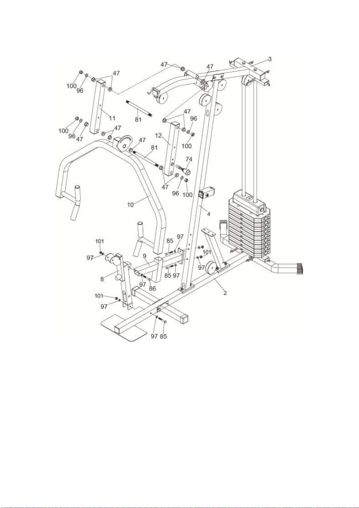
STEP 4
1. Attach the Left and Right Connect Frame (11&12) to the Upper Cross Beam (3), using six
Oil Bushings (47), Shaft (81), two M16 Washers (96) and two M16 Nylon Nuts (100).
2. Attach the Press Arm (10) to the Left and Right Connect Frame (11&12), using six Oil
Bushings (47), Shaft (81), two M16 Washers (96) and two M16 Nylon Nuts (100).
3. Insert the Quick Knob (long) (74) through the single hole on the Press Arm (10) to any
one of the holes on the fan-type plate.
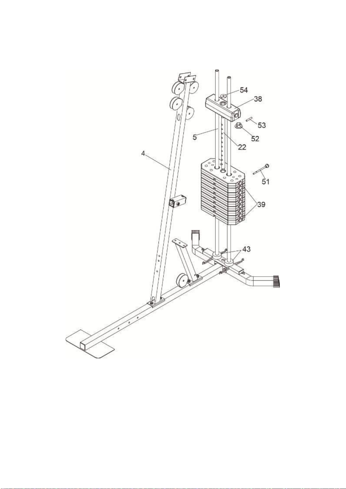
4. Attach the Seat Support Frame (9) to the Support Frame (4), using two M10X70mm Hex
Bolts (85), four M10 Washers (97) and two M10 Nylon Nuts (101).
5. Attach the Front Support Frame (8) to the Seat Support Frame (9) and the Base Frame
(2), using one M10X65mm Hex Bolt (86), one M10X70mm Hex Bolt (85), four M10
Washers (97) and two M10 Nylon Nuts (101).