OMX 333UNI
SETTING PROFI
OMX 333UNI
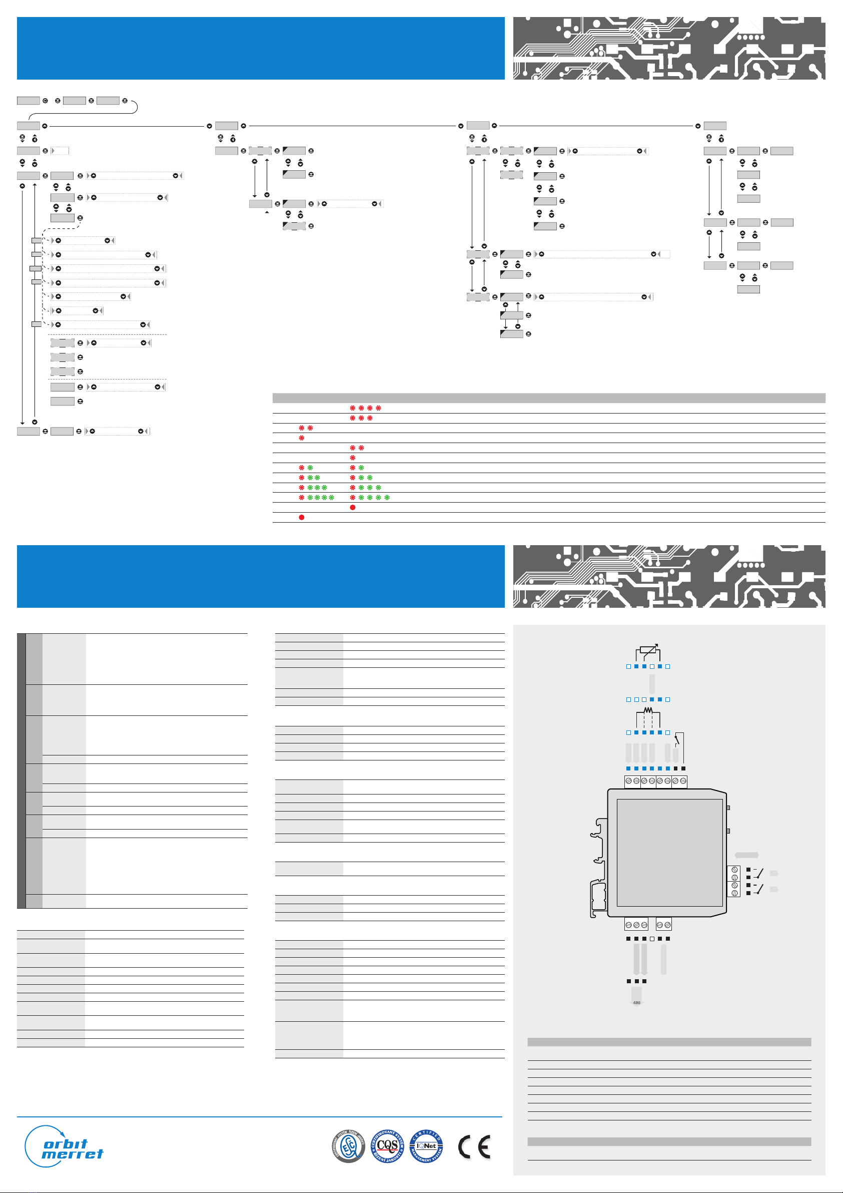
CONNECTION AND CONTROLLING OF INSTRUMENT / TECHNICAL DATA
142. 8 +PAS . 0
INP.CHA .SER.
OUT.
LI M . L. 1 RES .
SAV.
CLR.C. TA.
CFG .
C. A. MI N . 1
FI L .MOD.
CO N . 0
NO EXP.. RND.
MAX. 1
N.PA.
FI R .
USR.
YES
P. PR.
P. LI . 0
Zeroing of tare
Setting of measuring rate
Setting of instrument’s measuring mode
Setting for beginning of range
Setting the filtration constant
Setting the digital filters*
Setting for end of range
EXT. EX .1 OFF HLD. TAR..
Selection of auxiliary input function
Setting of baud rate
T.1 0
H.1 0
L.1 25
TYP.CLO. OPE. rDY. Err.
Setting of limit’s time delay
Setting of limit’s hysteresis
Setting of limit value
Selecting output mode**
Setting access passwords
Restoring manufacturer’s settings
CAL.
C.HI .
C.LO . 0
Calibratin of the range (DU)
M.P.S. 0.5 1.2 2.5 5.0 10.0 20.0
DC
PM
RTD
MOD
TYP DC PM T/C DU
I 0. I 4. E4. U 2. U 5. U10.
E0.1 E0.5 E1.0 U0.1 r.0.5 r0.1
T/C BEJ KN R S t L
30n 60m U.1
CO N .
R.AD . 0
LEA .
T. C.J . 0
2-u 3-u 4-u
CO N .IN.1 IN.2 EX.1 EX.2
0
Cu.1 Cu..2 Cu.3 Cu.4
Ni.5 Ni.6
E0.1 E0.5 E1.0 U0.1 r.0.5 r0.1
OHM
Selection of input and range
Setting for RTD
Setting for T/C
SET.
ADD. 0
DAT.DAUB 600 1200 2400 115200 230400
100A.Hi
0A.Lo
A. O. TYP.AV.i 20 E. 4. i 4. i 5. u 2 u 5 u10
Setting of address
Setting maximum for analogue output
Selecting output type
Setting minimum for analogue output
L. 2
ERROR MESSAGES
ERROR LED “LO” LED “HI” CAUSE SOLUTION
E.D. U . number is too low (or high negative) to be displayed (less than -99999) change setting of channel constant
E.D. O . number is too high to be displayed (greater than 99999) change setting of channel constant
E.T. U . number is out of table range (lower) widen values in table (add first line), change input setting (channel constants)
E.T. O . number is out of table range (greater) widen values in table (add last line), change input setting (channel constants)
E.I . U. input value is lower than permitted input range change value of input signal or change settings of input range
E.I . O. input value is greater than permitted input range change value of input signal or change settings of input range
E.HW.a part of the instrument is not functioning properly send to manufacturer to be serviced
E.E. E. data in EEPROM corrupted restore manufacturer’s settings, if error message reoccures, send to manufacturer to be serviced
E.D. T. data in EEPROM out of range restore manufacturer’s settings, if error message reoccures, send to manufacturer to be serviced
E.CL.memory was empty (pre-setting had taken place) if error message reoccures, send to manufacturer to be serviced, possibilty of corrupted calibration data
E.IN.input leads disconnected check leads and their connection
E.OU.output leads disconnected check leads and their connection
S+ S-E+ E-
ES-
E-
ES+
ES+
DC, PM
RTD, OHM, Ni
DU
T/C
S-
L2
L1
OM Link
123 45
1234
JKLMNONO
AO - current
AO - voltage
GND
Power supply
+
+
+
--
Rx/Tx-
Termination
Rx/Tx+
485
-
+
EXT.1
GND
+
+
INPUT 1
+
-
+
+
INPUT 2
INPUT 3
INPUT 4
INPUT 5
GND
+
-
INPUT 4
-
+
MEASURING RANGES - CONNECTION
TYPE INPUTS 1 INPUTS 2 INPUTS 3 INPUTS 4 INPUTS 5
DC ±20/±40/±80 V ±30/60 mV
±1 V ±80/±180 mA
PM ±2/±5/±10 V 0/4…20 mA
OHM 0…300 Ω/0…1,5 kΩ/0…3 kΩ/0…30 kΩ
RTD-PT Pt 100/Pt 500/Pt 1 000
RTD-CU Cu 50/Cu 100
RTD-NI Ni 1 000/Ni 10 000
T/C J/K/T/E/B/S/ R/N/L
DU Linear potentiometr (min. 500 Ω)
EXTERNAL INPUT
DESCRIPTION ACTION
EXT. 1 control input, functionality according to
setting in the menu (see Menu > EXT.1) upon contact, terminal (no. N + O)
Instrument‘s power supply leads should not be in vicinity of low level input signals. Contactors, medium and high power electrical motors must not be used in vicinity of the instrument.
Input signal leads (measured value) need to be separated from all high power leads and devices. Instruments are tested in accordance with standards for industrial use, however we
strongly advise you to adhere to the above mentioned precaution measures.
In order to ensure proper functionality of this instrument it is absolutely essential to connect the input leads shielding to the junction box‘ frame.
MEASURING INPUT
INPUT
DC Ranges
±80 mA < 1 V Input 5
±180 mA < 2 V Input 5
±30 mV > 10 MΩ Input 4
±60 mV > 10 MΩ Input 4
±1 V > 10 MΩ Input 4
±20 V 1 MΩ Input 1
±40 V 1 MΩ Input 1
±80 V 1 MΩ Input 1
PM Ranges
±20 mA < 200 mV Input 5
4...20 mA < 200 mV Input 5
±2 V > 10 MΩ Input 1
±5 V 1 MΩ Input 1
±10 V 1 MΩ Input 1
OHM Ranges
0…100 Ω
0...300 Ω
0...1,5 kΩ
0...3 kΩ
0…24 kΩ
0...30 kΩ (only for 2- or 4-wire)
Connection 2-, 3- or 4-wire
RTD Type
EU > 100/500/1000 Ω, w.3 850 ppm -50°…450°C
US > 100 Ω, with 3 920 ppm/°C -50°…450°C
RU > 50/100 Ω with 3 910 ppm/°C -200°…1 100°/450°C
Connection 2-, 3- or 4-wire
Ni Type Ni 1000/ Ni 10000 w.5 000 ppm/°C -50°…250°C
Ni 1000/ Ni 10000 w.6 180 ppm/°C -200°…250°C
Connection 2-, 3- or 4-wire
Cu Type Cu 50/Cu 100 with 4 260 ppm/°C -50°…200°C
Cu 50/Cu 100 with 4 280 ppm/°C -200°…200°C
Connection 2-, 3- or 4-wire
T/C Type
J (Fe-CuNi) -200°...900°C
K(NiCr-Ni) -200°...1 300°C
T (Cu-CuNi) -200°...400°C
E (NiCr-CuNi) -200°...690°C
B (PtRh30-PtRh6) 300°...1 820°C
S(PtRh10-Pt) -50°...1 760°C
R (Pt13Rh-Pt) -50°...1 740°C
N (Omegalloy) -200°...1 300°C
L (Fe-CuNi) -200°...900°C
DU Supply of linear
potentiometer 2,5 VDC/6 mA, min. resistance of potentiometer is 500 Ω
INSTRUMENT’S ACCURACY
TK 50 ppm/°C
Accuracy ±0,05 % of the range + 1 digit
±0,05 % of the range + 1 digit
Accuracy of cold
junction measurement ±1,5°C
Rate 0,5…80 measurements/s
Overload capacity 10x (t < 30 ms), 2x
Digital filtres exponencialn filter, rounding
Function Hold - “freezing the measured value”, Tare (upon contact)
External input 1, with the possibility of assigning various functions in
the instrument’s menu
OM Link Company communication interface for operating,
setting and updating of instruments
Watch-dog reset after 500 ms
Calibration at 25°C and40% r.h.
COMPARATOR
Type digital, setting in vmenu
Limits 0…999999
Hysteresis 0…999999
Delay 0…99,9 s
Outputs
up to 2x relays with switch-on contact (Form A),
(250 VAC/30 VDC, 3 A)*
2x open collector, (30 VDC/100 mA)*
Reaction speed < 50 ms
Relay 1/8 HP 277 VAC, 1/10 HP 125 V, Pilot Duty D300
* values apply to resistive load
DATA OUTPUT
Protocol ASCII
Data format 8 bit + no parity + 1 stop bit
Rate 600…230 400 Baud
RS 485 isolated, adressing (max. 31 instruments)
ANALOG OUTPUT
Type isolated, programmable with 12-bit D/A converter,
type and range are selectable in menu
Non-linearity 0,1 % of range
TK 15 ppm/°C
Rate response to change of value < 1 ms
Output 0…2/5/10 V, ±10 V, 0…5 mA, 0/4…20 mA
(comp. < 500 Ω/12 V), Detection of broken loop
Ripple 5 mV residual ripple at output voltage of 10 V
POWER SUPPLY
10…30 VDC/24 VAC, ±10 %, 3 VA, PF ≥ 0,4,
ISTP< 40 A/1 ms, isolated
MECHANIC PROPERTIES
Material PA 66, incombustible UL 94 V-0, blue
Dimensions 90,5 x 79 x 25 mm
Installation to DIN rail, wide 35 mm
OPERATING CONDITIONS
Connection connector terminal board, cross section < 1,5/2,5 mm2
Stabilization period within 15 minutes after switch-on
Working temperature -20°…60°C
Storage temperature -20°…85°C
Cover IP20
Execution safety class I
El. safety EN 61010-1, A2
Dielectric strength
2,5 kVAC after 1 min between supply/input
2,5 kVAC after 1 min between supply/outputs
4 kVAC after 1 min between input/relays output
Insulation resistance*
for pollution degree II, measuring cat. III.
power supply > 300 V (PI), 255 V (DI)
input/output > 300 V (PI)
input/output - relay > 300 V (DI)
EMC EN 61326-1 (Industrial environment)
* PI - Primary insulation, DI - Double insulation
ORBIT MERRET, spol. s r. o.
Vodňanská 675/30, 198 00 Prague 9, Czech republic
tel.: +420 281 040 200, fax.: +420 281 040 299
*Setting the digital filters
OFF filters are off
EXP. exponential filter
rnd. rouding
COn. setting of the calibration constant
**Selecting output mode
CLO. closing relay (normally open)
OPE. opening relay (normally closed)
rnY. all OK
Err. error indication
MINI-TECHDOK - OMX 333UNI - 2012 - 1v1 - en


