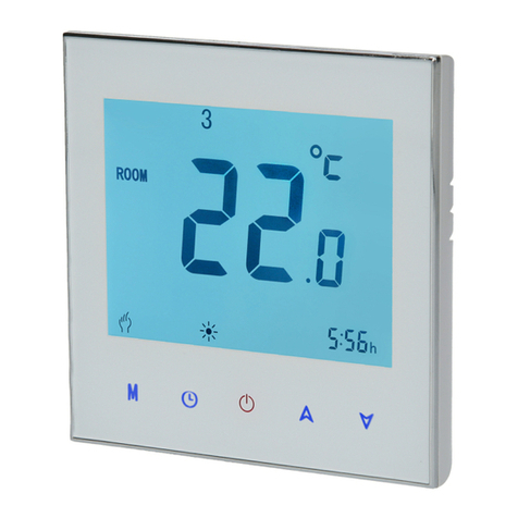
Orcomm ORC-24F-RS485 User manual

M_V1.0 –ORC-HC2-24
Manual for Local Room Controller Thermostat
ORC-24F-RS485, ORC-24C-RS485, ORC-24D-RS485
86 x 86 x 15mm
Contents
Introduction......................................................................................................................................................... 2
Versions........................................................................................................................................................... 2
Home Screen ....................................................................................................................................................... 3
Adjusting LRC....................................................................................................................................................... 3
Desired Room temperature............................................................................................................................. 3
Fan speed......................................................................................................................................................... 3
Lock Mode (optional) .......................................................................................................................................... 3
Enter Lock mode.............................................................................................................................................. 3
Exit Lock Mode ................................................................................................................................................ 3
Installer Mode ..................................................................................................................................................... 4
Installer Options .............................................................................................................................................. 4
Enter Installer Menu........................................................................................................................................ 4
Cabling................................................................................................................................................................. 4

M_V1.0 –ORC-HC2-24
Introduction
The ORC-HC2-24-RS485 Local Room Controller (LRC) is available in multiple versions.
Designed to work with Modbus addressed controllers or Gateways. The ORC-HC2-24-RS485 cannot work
stand alone. The LRC is designed to allow the User to see what state the climate controller is in. For example
Local Ambient temperature, desired temperature “set point”, Fan speed and other user changeable
features.
Installation of the LRC uses a standard UK single electrical box 45mm deep supplied separately.
Versions
Part code →ORC –HC2 –24C –RS485 –WH
Brand
LRC version
Technology control
Communication
Colour
ORC-HC2-24C-
RS485-WH
ORC-HC2-24D-
RS485-WH
ORC-HC2-24D-
RS485-WHF
ORC-HC2-24F-
RS485-WH
Screen
LCD
LCD
LCD
24V DC
(100mA)
Power
24V DC
(100mA)
24V DC
(100mA)
24V DC
(100mA)
24V DC
(100mA)
Data
RS485/Modbus
RS485/Modbus
RS485/Modbus
RS485/Modbus
LRC Ver
HC2
HC2
HC2
HC2
Bus filter
12v p-p
12v p-p
4v p-p
4v p-p
Sensors
Internal
Internal / External
Internal
Internal
Fan control
YES
YES
YES
YES
UFH Control
YES
YES
YES
YES
Local Control
NO
NO
NO
NO
Cabling
2x 2 pair
(Belden 9842)
Or
(Belden 9841 + 2
core power 0.3mm)
2x 2 pair
(Belden 9842)
Or
(Belden 9841 + 2
core power 0.3mm)
2x 2 pair
(Belden 9842)
Or
(Belden 9841 + 2
core power 0.3mm)
2x 2 pair
(Belden 9842)
Or
(Belden 9841 + 2 core
power 0.3mm)
Colour
White / Silver Frame
White
White / Silver Frame
External Sensor
N/A
10K NTC
10K NTC
N/A
Baud Rate
9600,19200,38400
9600,19200,38400
9600,19200,38400
9600,19200,38400

M_V1.0 –ORC-HC2-24
Home Screen
Adjusting LRC
Desired Room temperature
When you select on the Home screen will now show the desired SET point. Adjust using until
the correct temperature is displayed (SET point).
After 3 seconds the Home display will show the Ambient room temperature.
Depending on configuration of the controls equipment the system will start to operate the controls. The
change may take up to 3 minutes before operation starts.
Fan speed
The Home screen will display the current Fan speed [OFF,LOW,MID,HIGH,AUTO]
To change the Fan speed, press the symbol until the option on the Home screen is correct.
NOTE: If you manually take control of the fan speed it will stay at the speed irrelevant of temperature
difference.
Lock Mode (optional)
Enter Lock mode
Press and hold for 3 Seconds to lock the screen.
The icon will display on the Home Screen
Exit Lock Mode
Press and hold for 3 Seconds to lock the screen.

M_V1.0 –ORC-HC2-24
Installer Mode
Installer Options
Function
Setting / Option
Default
1
Offset / calibration
-1
2
Not available
00
3
Lock
00 = All the buttons are locked except power
01 = All the buttons are locked
01
4
Not available
01
5
Min set Temp
5 –15’C
18
6
Max set Temp
5 –35’C
32
7
Time Format
00 = 12 hour, 01 = 24 hour
01
8
Display Mode
00 = Set and Room Temperature
01 = only Set Temperature
00
9
Not available
1
A
Address
Modbus address (HEX)
01
B
Baud Rate
1
Enter Installer Menu
To Enter installer menu
1. Turn off the LRC (Home screen blank)
2. Press and hold and then until display changes (3 seconds)
3. Now choose option to change by using to toggle through options (note 3 sec time out)
4. Change the Default value using
5. Then move to next option using M
6. Setting will auto save when timed out
Best practice when finished setting up the LRC, turn all power OFF and ON again to allow controls to reset.
Cabling
2 versions of cable entry on rear of unit
Version 1 flying lead (RED/WHITE) to connect to for RS485 connection
Version 2 terminal on rear for A B [A = RS485+, B = RS485 -]
Version 1 Version 2
Additional notes
Long cable runs on Modbus will require 120 ohm ¼W end of line resistor.
BIAS Resistors can be used at the beginning of the bus to help control higher than normal voltages.
Example 120 ohm across A & B, 1K across A and 12VDC, 1K across B and GND –NOTE turn off before
installing resistors.
This manual suits for next models
2
Other Orcomm Thermostat manuals