OREC HRC663 User manual

INSTRUCTION MANUAL
HRC663/673/813
Grassland walk behind flail mower
Read this instruction manual carefully before any use of the machine, keep it as a reference.For any
question about this manual, please report to your OREC dealer or to the distributor of your country or
to : http://www.orec-jp.com.
Update : June 2020

2
“Only the English version of this manual can be used as a reference.”
INTRODUCTION
Forward to the user
Read this manual before any use of your mower, only the herein instructions shall help you to achieve
an efficient and safe work.
A safe use will only result from the manner you will use the machine in accordance with the
restrictions described in this manual. Thus, you must know and follow all the safety measures in this
manual and those relating to the use of your mower.
The MOWER that you have just bought has been designed and manufactured for your entire
satisfaction. As any other mechanical machine, it requires a proper maintenance and must be kept
clean. Grease the machine like indicated. Follow the rules and safety indications as described in this
manual and as showed on the preventive instruction stickers.
About maintenance, always mind that your OREC dealer has the skills, the genuine parts and the
necessary tools to solve the possible problems.
Use only the OREC original parts : “ non genuine ” parts will not assure you of a correct and safe
working and are likely to make the guarantee null and void. Write the name and the serial number of
your machine hereunder :
MODEL :.......................................................................................
SERIAL NUMBER (refer to the pictures herein) :.........................
Always mention these information to your dealer in order to obtain the right parts.
Concerned about constant progress, OREC keeps the right to modify the machines without being
compelled to modify those already sold.
The illustrations and characteristics in this manual might lightly differ from your machine because of
the constant improvements made by our production department.
In this manual, the left and the right hand or the rear and the front position are determined according
to the mower handlebar.
All along this manual the word IMPORTANT is used to indicate that a fault might cause damage to
the machine. The words WARNING, CAUTION and DANGER are used with the “ safety/warning ”
pictogram (triangle with an exclamation mark) in order to indicate a hazard for your safety.
This symbol indicates that you must be very attentive because your safety is at stake. It reminds that
you must follow the safety instructions and pay attention to hazardous operations that might cause
injuries.
WARNING
Reminds the safety rules that might cause injury if they are not respected.
CAUTION
Remembers to pay attention to a real danger that is likely to cause injury or even death if no proper
precaution is taken.
DANGER
Indicates a major hazard that is most likely to cause irremediable injury or death if the right
precautions are not taken.

3
CONTENTS
INTRODUCTION ................................................................................................................................................2
CONTENTS ........................................................................................................................................................3
SPECIFICATIONS ..............................................................................................................................................3
CHECK LIST .......................................................................................................................................................4
SAFETY RULES .................................................................................................................................................5
DIFFERENT PARTS OF THE MOWER .............................................................................................................6
SAFETY INSTRUCTION STICKERS .................................................................................................................7
CONTROLS ........................................................................................................................................................9
OPERATION.....................................................................................................................................................12
MAINTENANCE OPERATIONS TO BE CARRIED OUT BY THE USER ........................................................14
BREAKDOWNS AND SOLUTIONS .................................................................................................................21
TIGHTENING TORQUES (Nm)........................................................................................................................22
EC CONFORMITY DECLARATION .................................................................................................................23
MEASUREMENT OF VIBRATIONS .................................................................................................................23
EC CONFORMITY DECLARATION .................................................................................................................24
MEASUREMENT OF VIBRATIONS .................................................................................................................24
EC CONFORMITY DECLARATION .................................................................................................................25
MEASUREMENT OF VIBRATIONS .................................................................................................................25
LIMITED WARRANTY ......................................................................................................................................26
NOTES..............................................................................................................................................................26
SPECIFICATIONS
Model
HRC663 HRC673 HRC813
Engine
HONDA GX270 HONDA GX270 HONDA GX340
Engine power(HP)
8.45Hp 8.45Hp 10.7Hp
Transmission
Mechanical Mechanical Mechanical
Forward speed(km/h)
(1) 0.95, (2) 1.99, (3) 3.50 (1) 0.95, (2) 1.99, (3) 3.50 (1) 0.95, (2) 1.99, (3) 3.50
Reverse speed(km/h)
0.95 0.95 0.95
Cutting width (mm)
650 650 800
Height of cut (mm)
50 to 110 50 to 110 50 to 110
Weight (kg)
170 170 190
Fuel tank(liters)
5.3 4.1 4.7
Blade transmission
belts belts belts
Blade engagement
belt tension belt tension belt tension
blade speed (rpm)
3075 3075 3075
Over all width (mm)
810 810 940

4
CHECK LIST
INSTRUCTIONS TO THE DEALER
• The assembling, the installation and the first application of the machine is under the OREC dealer’s
responsibility.
• Read the instruction manual as well as the safety measures. Check that all the before delivery and
at delivery check points specified in the following lists have been verified and possibly modified before
delivering the machine to its owner.
CHECKS BEFORE DELIVERY
• Check that all the shields, grids and safety guards are in place and in a good condition.
• Check that the hydraulic hoses are in place and in a good condition. Replace them if necessary.
• Check that there is no oil leak, repair if necessary.
• Check that the safety instruction stickers are in place and in a good condition. Replace them if
necessary.
• Check that all the bolts and screws are properly tightened with the right torque (refer to torque chart).
• Protect the grease nipples by coating them with grease and lubricate the machine.
• Check that the machine can work properly.
CHECKS ON DELIVERY
• Show the user how to perform the adjustments.
• Explain to the user the importance of the lubrication and show him the different greasing points on
the machine.
• Show him the safety devices, grids, guards and the optional equipment.
• Give the instruction manual to the customer, ask him to read it carefully.

5
SAFETY RULES
CAUTION
Some of the illustrations show the machine with no guard, no shield. Never use the machine
without these devices.
•Learn to stop the machine in case emergency.
•Read this manual.
•Do not let anybody use the machine before having read and understood this
manual.
•Do not let children use the machine.
•Do not wear loose clothes. They might be grasped by moving parts.
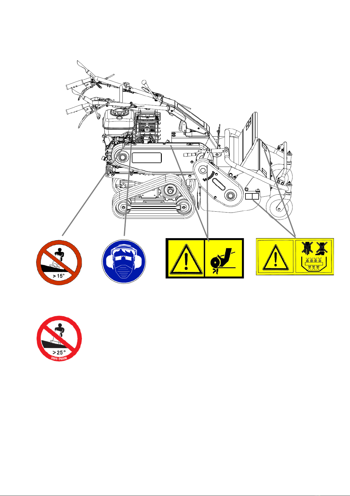
•Always wear protection equipment when using the machine.
•Only work during daylight or with good artificial light.
•Check that the safety instruction stickers are in place and in a good condition.
•Keep the machine free from debris or mud.
•Check that the machine can work properly before any use.
•Check that all the shields, grids and safety guards are in place and in a good state.
•It is strictly forbidden to carry persons or animals onto the machine during the work or during the
transportation.
•Never stop or start roughly when working on a slope. Never use the machine to work on a stepping
terrain.
•Reduce the ground speed when running on a slope and when turning
straight in order to prevent from any risk of losing control.
•Be very careful when bordering ditches.
•Stop the engine, and remove the sparking plug ignition cover before any
intervention on the machine.
•Never work under the machine or its parts when lifted, unless they are
blocked and maintained into position with sufficient security.
•When running on a slope, basically work going up or down. In case of
going across the slope, respect the limit angle on slope.
•Steer clear of unsteady embankments, holes or rocks. They might be dangerous during manoeuvres
or transport.
•Keep away from electric wires and obstacles. A contact with electric wires causes electrocution and
death.
•Stop the engine when lifting or transporting the machine.
•When stopping the work, stop the engine and remove the sparking plug ignition cover before leaving
the mower.
•Engage all the safety equipment.
•Move the controls only when correctly sat down in the mower
•Visually check hydraulic leaks and if some parts are faulty or missing. Repair before use.
•Never change the adjustment of the regulator, it is set in the factory. Unsetting this valve would
cause failures.
•Ensure that the user of the machine has already read and understood this
manual and is aware of all the safety instructions before any use.
•Always use a chuck and bronze hammer when replacing or intervening
on the pins and bolts at the end of rams, rod … etc. in order to avoid the
projection of metal fragments.
•Clear the mowing path from foreign objects, stones, woods, cans, bottle,
pieces of steel, which can be thrown by the mower.
•Gasoline is highly flammable :
- Refuel outside, never smoke when refueling
- Never refuel when the engine is running, stop the engine before refueling
- Allowed the engine to cool down before refueling
- If gasoline has spilled, do not try to start engine before the spilled gasoline has been wiped.
- Check that the fuel cap is correctly installed after refueling
•

6
DIFFERENT PARTS OF THE MOWER
Side clutch
lever
Handlebar
adjustment
UP/DOWN
Cutting
height
adjustment
Rotary cover
Safety cover
Front
Driving clutch
lever
Left
Right
Rear
Throttle
Air filter
Starter
Fuel cock
Blade clutch
locking lever
Fuel tank
Handlebar
adjustment
(L /R)
Blade tension
lever

7
SAFETY INSTRUCTION STICKERS
Note their location and replace them immediately in case of damaged or when missing
Unplug the spark plug
wire before performing
maintenance, read
owner’s manual
Beware of thrown objects
Keep away from the
machine
Read owner’s manual
No hands or feet under the
mowing deck
Read owner’s manual to be aware of the risks such as
burns, breathing intoxication, and fire

8
SAFETY INSTRUCTION STICKERS (continued)
Do not exceed 15°
slopes (HRC663)
Do not exceed 25°
slopes (HRC673, 813)
Always wear
protective equipment
against dust, noise
and wear glasses
Beware of rotative belt under the
shield
No hands or feet under
the mowing deck

9
CONTROLS
DRIVING CLUTCH LEVER
Push the lever (1, Figure 1) down to the
handlebar to make the machine move. Release
the lever, then the machine stops.
BLADE CLUTCH LEVER
Blade clutch lever makes the engine drive the
blade to mow. Push the lever (2, Figure 1) then
pull up the lever (3, Figure 1) to make the blade
spin.
Release the lever, then the rotor stops.
WARNING
Never try to start or stop the engine with
blade engaged.
SPEED LEVER
This lever (4, Figure 1) allows to select 3 forward speeds (1, 2, 3), 1 reverse speed (R) or 1 neutral
position(N).
WARNING
Be sure to change speed only when driving clutch is disengaged and machine is stopped.
THROTTLE LEVER
Push the throttle lever (5, Figure 1) to left to increase engine speed, push the throttle lever to right to
decrease engine speed to idle rpm. Always operate mower at full engine speed.
SIDE CLUTCH LEVERS
The side clutch levers (6, Figure 1) are used to change the direction of the machine. Grip right lever to
turn right and left lever to turn left. To move the machine when engine is cut off, grip the both levers.
DANGER
Do not grip two levers on slopes when engine is running.
HANDLEBAR ADJUSTMENT LEVERS
Grip the lever (7, Figure1) to move handlebar right and
left. And grip the lever (8, Figure 1) to move handlebar
up/down.
CHOKE LEVER (1,FIGURE 2)
Push this lever to X to operate the choke to start engine
cold, when engine has start release it to Y.
IMPORTANT
There is no need to choke when the engine is hot.
Figure 1
1
3
4
2
6
8
6
Y
X
1
7
5
2
Figure 2
X
Y
1
2

10
FUEL COCK (2, FIGURE 2)
Open fuel cock before using the machine. Close fuel cock when machine is not in use. Push the lever
to Y to open fuel cock and to X to close cock.
HEIGHT OF CUT CONTROL
Height of cut can be adjusted by turning the crank-lever
(1, Figure 3) clockwise to increase the height of cut and anti-
clockwise to lower the height of cut.
WARNING
Always perform this adjustment with engine off and
sparking plug cover unplugged. When cutting low, more
power is needed and more objects are thrown. Cutting low
can cause damage to the machine and injuries.
ENGINE ON/OFF SWITCH
This switch is located on the left side of the handlebar. It allows
to run the engine when positioned on « ON » and stop the
engine when positioned on “OFF”. (Figure 4) Use this switch to
start or stop the engine.
ENGINE :
Refer to engine manual delivered with the machine.
CRAWLER LOCK LEVER ( HRC673 / 813 ONLY)
This lever is located on the left side of handlebar.
It is used to function for uplift prevention of machine by locking both crawlers.
Grip the lever (1, Figure 5) until it clicks into place and is locked by lever (2, Figure 5). In this moment,
crawler is unlocked.
Grip lever (1, Figure 5) again with lever (2, Figure 5) and release it. Then crawler kit pin should fit into
one position. Then crawler is locked.
CAUTION
When crawler is locked, turning radius would be
slightly bigger than normal operation.
Figure 5
1
2
Figure 3
1
Figure 4

11
ROTARY COVER (1, FIGURE 6)
The blade spins at a high speed inside the cover. This cover
prevents cut grass and foreign objects from scattering.
FRONT COVER (2, FIGURE 6)
This opens and closes automatically depending on the quantity of
grass. This prevents cut grass and foreign objects from scattering
forward.
SAFETY COVER (3, FIGURE 6)
This prevents cut grass and foreign objects scattering from
coming at the mower.
WARNING
The covers are the really important parts to protect from thrown objects.
Do NOT attempt to operate the machine if the covers are in abnormal conditions. Make sure to
follow the instruction below.
1. If Rotary cover, Front cover or Safety cover is damaged or deformed, have it repaired or
replaced.
2. Do NOT attempt to operate the machine without Front cover and Safety cover.
3. Do NOT attempt to operate the machine with Front cover fixed. Fix Front cover ONLY when
replacing the blade or cleaning inside of the cover.
Figure 6
2
3
1

12
OPERATION
CAUTION
Check the tightening of bolts, referring to the tightening torque chart
The safety is one of our main worries when designing and manufacturing this machine. Negligence in
the use of the machine spoils our efforts. The prevention strictly depends on the care and on the skill
of the user when applying and maintaining the machine. The best safety method remains a careful
and skilled user ; we hope you to be this kind of user.
The user of this machine is responsible for its safe use. He must be a skilled user specially trained for
the use of this machine. Read the safety instructions. This machine has been designed to mow grass.
It is not designed for any other operation. It is not designed to transport other tools or materials that
might damage it and cause injuries to the user. It must not be used to carry persons.
DANGER
Never use the machine without having priory carried out all the maintenance operations as
described in the daily maintenance chapter.
CAUTION
Never let children or unskilled persons use the machine. Check that nobody or no objects
stands near the machine when at work. They could be hit by the moving parts. Nobody must
stand on the machine except the driver. Never put your hands under moving parts.
STARTING OF THE ENGINE
•Turn the fuel cock to "ON".
•Check that cutting blade is disengaged, and Driving lever range is in neutral position « N ».
•Push choke lever if engine is cold or push throttle lever half of his stroke if the engine is hot.
•Pull the starter rope.
•When the engine has started, pull back the choke lever.
•Select a speed ratio and travel to the mowing path.
DRIVING ON SLOPES
Driving on a slope is very dangerous. For your safety,
never work on a more than 15°(HRC663) / 25°
(HRC673 / 813) slope. Also, be careful even when
you work on a slope of less than the limited degree.
The unit might tip over depending on field condition.
Ii
Basically, drive up or down.
In case of driving across the slope, it is safe to turn
from low level to high level(Figure 7). If machine is
turning from high level to low level, it is difficult to turn
properly and it is very dangerous.
WARNING
It is very dangerous to disengage the driving clutch on slopes unnecessarily or to shift the
change lever into neutral position.
Figure 7

13
MOWING
•Start the engine
•Adjust the height of cut as needed.
WARNING
Do not forget that it is better to mow grass regularly. Remember that the machine gets
deteriorated rapidly in the hot and dry weather. When cutting height is low, the blade may hit
the ground and get damaged. The user and bystanders are likely to get injured by the thrown
objects. The thrown objects may cause damage to properties.
•Increase engine speed to the maximum.
•Push down the blade clutch lever (1, Figure 8) then
engage the blade tension lever (2, Figure 8) slowly.
•Then go forward in the grass to mow.
•The best cutting speed depends on quantity and the
density of the grass. Usually, it is asked to mow
between 1st and 2nd speed. Tall grass should be cut
slowly and short grass can be cut faster.
CAUTION
Clear the mowing path from foreign objects, stones,
woods, cans, bottles and pieces of steel which can be thrown by the mower. They can cause
injury to the operator or the bystanders.
HOW TO STOP THE MACHINE
•Release drive clutch lever and blade clutch lever.
•Push the throttle lever to “LO”.
•Switch the engine stop on “off”
•Close the fuel cock
•Remove the spark plug wire
CAUTION
Never park the machine on slopes. Park it on a level and flat surface.
STORING THE MACHINE
Thoroughly clean the machine. Use touch up paint to prevent rust. Check for worn and damaged
parts, install new parts as required. Perform the normal maintenance of the machine according to
maintenance chart. Store the machine in a dry protected area. Remove sparking ignition wire from the
sparking plug.
TRANSPORT
•Check that the cutting rotor is disengaged.
•Check that the spark plug cover is disconnected.
•Check that the fuel cock is closed.
CAUTION
Take care of hot surfaces of the machine, especially around the engine.
Figure 8
1
2

14
MAINTENANCE OPERATIONS TO BE CARRIED OUT BY THE USER
DANGER
BEFORE performing any maintenance operation on the machine, stop the engine, and remove
the spark wire from the sparking plug.
If maintenance operation is not realized, the machine can get damaged
easily and cause personal injuries to the user and/or bystanders. These
damages and injuries will not be covered by the warranty.
•Daily maintenance should be performed by the user.
•Maintenance operations for first 20 hours, 100 and 300 should be
realized by the dealer.
•Ask your dealer to check the machine if you find some problems.
•Ask your distributor the name of your dealer.
DAILY MAINTENANCE,BEFORE START MOWING
Transmission oil level : Loosen the bolt of the oil gauge (1 Figure 9), if the
level is correct, the oil level should appear in the gauge.
Transmission oil replacement.
•Gear Oil : SAE90 or API GL-5
•Gear Oil Quantity : 1.60L
Put a container under the right side of the transmisson to receive old oil,
remove the drain plug (3 Figure 10).
Then, fix the drain plug (3 Figure 10).
Put the oil from the oil cap (2, Figure 9)
Oil Exchange Frequency
First : 20 hours
Later : each 100 hours or every year whichever comes first
FUEL (FIGURE 11)
Check tank level is full before start to work. Check that tank cap is fully closed, and check for leaks.
Use only good quality unleaded gasoline.
DANGER
Check fuel tank is closed, wipe fuel spillages before
start the machine. Check there is no fire, electric sparks,
cigarettes near the machine when refueling.
Figure 9
Figure 10
Figure 11
1
2
3

15
SAFETY STICKERS
•Check safety stickers are labeled on their place. Replace
them if they are worn and damaged.
AIR FILTER
- Open the air cleaner cover and remove the dual-filter
elements.
- Remove the foam filter element from the paper filter
element.
- Clean paper filter element with compressed air (read the
engine manual).
- Clean foam filter element with soapy water, and dip in oil
(read the engine manual).
- Install the elements and air cleaner cover referring the
engine manual.
ENGINE OIL LEVEL :
•Refer to engine manual. With the engine cold or stopped at least
for 10 minutes on a level place. Check level with the oil filter cap
(1, Figure 13). Unscrew the plug, wipe it and install without
screwing it. Check the level. That must be between the two marks.
•Engine oil : SAE 10W30 or API SL class
•Engine oil quantity : 1.10L (HRC663)
1.28L (HRC673/813)
Remove oil drain plug (2, Figure 13) in case of changing oil.
Engine oil replacement
BLADE AND BLADE HOLDER CONDITION
CAUTION
You can be cut and injured by cutting flails. Always wear gloves when holding flails.
Check if flails are in good condition. Change worn or
damaged parts.
•Changing flails : unscrew hexagonal bolt on the rotor.
•Check the blade condition. Change it if it is worn, bent or
cracked.
•Reverse flails if the cutting side is worn out in order to use
the other side.
•Check that ALL the flails of the rotor are bolted and in good
condition
•Check tightening of hexagonal screws according to the
chart at the end of the manual.
First : 20 hours.
Later : every 100 hours or every year whichever comes first.
AIR CLEANER COVER NUT
AIR CLEANER COVER
WING NUT
PAPER FILTER ELEMENT
SILENCER NOSE
FOAM FILTER
GASKET
Figure 12
Figure 14
Figure 13
1
2

16
CAUTION
Use only original genuine OREC parts. Other parts may be dangerous for your health and for
the bystanders and the machine. If some flails are missing, big vibrations will occur. If you feel
such vibrations on the handlebar, check the rotor and the flails. Vibrations may loosen the
bolts and nuts and may crack the steel of the machine.
TIGHTENING OF BOLTS AND NUTS
•Check for tightening of bolts and nuts according to the chart. Vibrations of the
machine may loosen bolts and nuts.
LUBRICATION :
•Grease the front wheel axle (1, Figure 15) with grease NLGI N°2.
•Grease the different points (G, Figures 16,17) with light oil.
WIRES GAP :
Transmission wires :
•If the machine does not stop when the drive clutch lever is released, adjust the tension wire as
follow : unscrew the locking screw (A, Figure 18) and unscrew the nut (B, Figure 18). Try the machine
again. Perform the adjustment again if needed. When the adjustment is performed, screw the locking
screw (A, Figure 18) on the nut (B, Figure 18).
•If the machine does not move when driving clutch lever is pressed, adjust the tension wire as
follow : unscrew the locking screw (C, Figure 18) and unscrew the nut (D, Figure 18). Try the machine
again. Perform the adjustment again if needed. When the adjustment is performed, screw the locking
screw (C, Figure 18) on the nut (D, Figure 18).
Figure 15
Figure 16
Figure 17
E
F
A
B
Figure 16
Figure 18
Figure 19

17
Blade wire :
•If the blade does not stop when the blade lever is released, adjust the tension wire as follow :
unscrew the locking screw (A, Figure 19) and unscrew the nut (B, Figure 19). Try the machine again.
Perform the adjustment again if needed. When the adjustment is performed screw the locking screw
(A, Figure 19) on the nut (B, Figure 19).
•If the blade does not move when transmission lever is pressed, adjust the tension wire as follow :
unscrew the locking screw (A, Figure 19) and after screw the nut (B, Figure 19). Try the machine
again. Perform the adjustment again if needed. When the adjustment is performed screw the locking
screw (A, Figure 19) on the nut (B, Figure 19).
Blade brake is connected to the blade wire. Check if the blade brake works correctly when
adjusting blade wire control.
Direction wires :
If the wheel is not locked with side clutch lever engaged, adjust as follows:
•Unscrew locking nut (E, Figures 18,19).
•Screw or unscrew the nuts (F, Figures 18,19) .
•Try the machine.
•Adjust again if it is necessary.
•Screw the locking nut “E” on the adjusting nuts “F”.
Handlebar Control wire adjustment
If the handlebar control doesn’t work correctly, adjust as follow :
- If it is difficult to free the handlebar, unscrew the nut (A, Figure 20,21), then screw the nut B to
increase the wire tension. When the adjustment has been performed, screw the nut A again.
- If the handlebar doesn’t lock properly, unscrew the nut (A, Figure 20,21), then unscrew the nut A to
decrease the wire tension. When the adjustment has been performed, screw the nut B again.
A
A
B
B
Figure 20
Figure 21

18
BELTS ADJUSTMENT:
WARNING
A loosened belt may slip and get worn quickly, a too tightened belt may wear out bearings.
•Check for belt condition, cracks and wear. Replace if necessary.
Belt from engine to counter shaft
•Stop engine and disconnect sparking cover, clutch the blade.
•Unscrew the three bolts of the shield to reach the belts.
•Push the belt with a finger on (A, Figure 22) the belt must
move from 10 to 12 mm. If the belt does not move accordingly,
perform “tension wire” again.
•Check that the belt guides (B, Figure 22) are close 3 or 4 mm
from the tighten belt.
•If it is necessary, adjust the belt guides as follow : unscrew
bolt (C, Figure 22) and adjust belt guides as required and
screw the bolt again.
•Fit the belt cover with the three bolts.
Belt from the counter shaft to the flails
•Stop engine and disconnect sparking cover.
•Unscrew the 2 bolts of the shield to reach the belt.
•Push the belt with a finger on (F, Figure 23) the belt must move
from 3 to 5 mm. If the belt does not move accordingly, adjust with
screws (A, Figure 23) & (B, Figure 23)
•Fit the belt cover with the two bolts.
Belt transmission adjustment
•Stop engine and disconnect sparking cover, clutch the blade.
•Unscrew the three bolts of the shield to reach the belts.
•Push the belt with a finger on (A, Figure 24) the belt must
move from 12 to 14 mm. If the belt does not move accordingly,
perform “tension wire” again.
•Fit the belt cover with the three bolts.
BLADE BRAKE :
WARNING
Check the blade brake every month (1, Figure 25), check the time for
the blade to stop when blade clutch lever is released. If more than 7
seconds are necessary for the blade to stop, ask your dealer
immediately to check the blade brake system.
3-4mm
3-4mm
C
A
10-12mm
Figure 25
1
Figure 23
A
B
F
3-5mm
Figure 24
A
12-14mm
B
Figure 22

19
CRAWLER ADJUSTMENT
WARNING
Crawlers tend to be stretched at first and gradually get suited for the sprocket.
When the tension of crawler is not adjusted correctly, the crawlers might be taken off, or the life time
can be shortened. Adjust crawler tension as follows.
Check crawler tension every 50 hours of use.
1. Remove the crawler cover and bolt.
2. Loosen locknut (A, Figure 27) in the rear part of the machine.
3. Turn the tension bolt (B, Figure 27) clockwise to increase the crawler tension and counterclockwise
to decrease.
4. The free play of the belt should be between 10 to 20 mm by pushing with hand.
5. Adjust crawler tension, both side crawler should be the same tension.
6. After adjusting, fix locknut certainly and crawler cover.
A
B
Figure 27
Bolt
Bolt
Crawler Cover
Axle Pin
Figure 26
Figure 28
10-20mm

20
MAINTENANCE CHART
Accidents or troubles can be caused if you do not inspect and maintain the machine. Inspect and
maintain as below in order to keep the machine work good and safe.
* For engine, refer to engine manual.
Frequency : D / Daily
M / Monthly
Y / Yearly
PART INSPECTION DETAIL
FREQUENCY
D
M
Y
Belt
tension
Tension is right.
○○○
damage, stains and dirt
There are no cracks, damage
or excessive dirt.
○○
Trans-
mission
strange noise and heat
There are no strange noise or heat.
○○
oil gauge and dirt
Transmission oil level is adequate and
the oil is not excessively dirty.
○
oil leakage
There are no visible oil leaks
from oil seal and packing.
○○○
Body
Frame
cracks, deformation
bolts and nuts
There are no cracks or deformation.
Bolts and nuts are in place and tight.
○○
Cover cracks, deformation, corrosion
There are no cracks,
deformation, or corrosion.
○
Flapper
damage, defects and loss
There are no damage, defects or loss.
○○○
Lever
Wire
Crawler
damage, loose
split pins loss
There are no noticeable damage, loosen-
ing.
Split pins are in place.
○○○
tension (crawler)
Tension is right.
○○○
cracks, damage, wear-out
There are no cracks, damage or wear-out.
○○○
stuck metal pieces,
stones or etc.
There are no metal pieces,
stones or etc. stuck.
○○○
loosening or loss
of bolts and nuts
Bolts and nuts are in place and tight. ○○○
strange noise and loosening
There are no loosening or strange noise.
○○
Blade
Rotary
damage and balance of blade
Blades are not broken, chipped,
cracked or bent.
Blades are balanced.
○○○
loosening of blade setting bolt
Blade setting bolts are in place and tight.
○○○
rotary cover
There are no cracks,
deformation, or corrosion.
○○
Label
damage
All safety stickers are in place and legible.
○○
This manual suits for next models
2
Table of contents
Other OREC Lawn Mower manuals