OREC RM83G User manual

INSTRUCTION MANUAL
GRASSLAND MOWER RABBIT
RM83G / RM830
Read this instruction manual carefully before any use of the machine, keep it as a reference.For any
question about this manual, please report to your OREC dealer or to the distributor of your country.
OREC CO LTD
548-22 HIYOSHI HIROKAWA-MACHI YAME-GUN JAPON
http://www.orec-jp.com
UPDATE : December 2020

OREC RM83G - © SAT 03/2015
2
“only the English version of this maual can be used as a reference.”
INTRODUCTION
Forword to the user
Read this manual before any use of your mower, only the herein instructions shall help you to achieve
an efficient and safe work.
A safe use will only result from the manner you will use the machine in accordance with the
restrictions described in this manual. Thus, you must know and follow all the safety measures in this
manual and those relating to the use of your tractor.
The MOWER that you have just bought has been designed and manufactured for your entire
satisfaction. As any other mechanical machine, it requires a proper maintenance and must be kept
clean. Grease the machine like indicated. Follow the rules and safety indications as described in this
manual and as showed on the preventive instruction stickers.
About maintenance, always mind that your OREC dealer has the skills, the genuine parts and the
necessary tools to solve the possible problems.
Use only the OREC original parts : “ non genuine ” parts will not assure you of a correct and safe
working and are likely to make the guarantee null and void. Write the name and the serial number of
your machine hereunder :
MODEL :.......................................................................................
SERIAL NUMBER (refer to the pictures herein) :.........................
Always mention these informations to your dealer in order to obtain the right parts.
Concerned about constant progress, OREC keeps the right to modify the machines without being
compelled to modify those already sold.
The illustrations and characteristics in this manual might lightely differ from your machine because of
the constant improvements made by our production department.
In this manual, the left and the right hand or the rear and the front position are determined according
to the tractor seat.
All along this manual the word IMPORTANT is used to indicate that a fault might cause damage to
the machine. The words WARNING, CAUTION and DANGER are used with the “ safety/warning ”
pictogram (triangle with an exclamation mark) in order to indicate a hazard for your safety.
serial
number
SERIAL NO.

OREC RM83G - © SAT 03/2015
3
This symbol indicates that you must be very attentive because your safety is at stake. It reminds that
you must follow the safety instructions and pay attention to hazardous operations that might cause
injuries.
WARNING
Reminds the safety rules that might cause injury if they are not respected
CAUTION
Remembers to pay attention to a real danger that is likely to cause injury or even death if no proper
precaution is taken.
DANGER
Indicates a major hazard that is most likely to cause irremediable injury or death if the right
precautions are not taken.
CONTENTS
INTRODUCTION ................................................................................................................................................2
SPECIFICATIONS..............................................................................................................................................3
CHECK LIST .......................................................................................................................................................4
SAFETY RULES .................................................................................................................................................4
MACHINE DESCRIPTION..................................................................................................................................6
SAFETY INSTRUCTION STICKERS .................................................................................................................7
CONTROLS ........................................................................................................................................................9
OPERATION.....................................................................................................................................................13
MAINTENANCE OPERATIONS TO BE CARRIED OUT BY THE USER ........................................................15
BREAKDOWNS AND SOLUTIONS .................................................................................................................22
TIGHTENING TORQUES (Nm)........................................................................................................................22
EC CONFORMITY DECLARATION .................................................................................................................23
MEASUREMENT OF VIBRATIONS .................................................................................................................23
EC CONFORMITY DECLARATION .................................................................................................................24
MEASUREMENT OF VIBRATIONS .................................................................................................................24
LIMITED WARRANTY ......................................................................................................................................25
NOTES..............................................................................................................................................................25
SPECIFICATIONS
Model
RM83G
RM830
Engine
HONDA GXV 390
HONDA GXV390
Transmission
Mechanical
Hydrostatic
Forward speed (km/h)
4 position 1.9/3.1/5.1/7.9
0 - 10
Reverse speed (km/h)
2.2
0 - 4.5
Cutting width (mm)
820
820
Height of cut (mm)
50 - 110
50 – 110
Weight (kg)
248
240
Fuel Tank (liters)
11
11
Blade transmission
belt
belt
Steering
gears
gears
Blade engagement
Belt tension
Belt tensio
Blade speed (rpm)
1300
1353
Width (mm)
990
990

OREC RM83G - © SAT 03/2015
4
CHECK LIST
INSTRUCTIONS TO THE DEALER
The assembling, the installation and the first application of the machine is under the OREC dealer’s
responsability.
Read the instruction manual as well as the safety measures. Check that all the before delivery and at
delivery check points specified in the following lists have been verified and possibly modified before
delivering the machine to its owner.
CHECKS BEFORE DELIVERY
• Check that all the shields, grids and safety guards are in place and in a good state.
• Check that the hydraulic hoses are in place and in a good state. Replace them if necessary.
• Check that there is no oil leak, repair if necessary.
• Check that the safety instruction stickers are in place and in a good state. Replace them if necessary.
• Check that all the bolts and screws are properly tightened with the right torque (refer to chart).
• Protect the grease nipples by coating them with grease and lubricate the machine.
• Check that the machine can work properly.
CHECKS ON DELIVERY
• Show the user how to perform the adjustments.
• Explain to the user the importance of the lubrication and show him the different greasing points on
the machine.
• Show him the safety devices, grids, guards and the optional equipments.
• Give the instruction manual to the customer, ask him to read it carefully.
• Explain to the customert that drive on the public roads is forbidden.
SAFETY RULES
CAUTION
Some of the illustrations show the machine with no guard, no shield. Never use the machine
without these devices.
CAUTION
Never go on public roads with the machine. The mower is not allowed to go on public roads.
Always use a truck or a trailer to go from a mowing area to another.
•Learn to stop the machine in case emergency.
•Read this manual.
•Do not let anybody use the machine before having read and understood this
manual.
•Do not let children use the machine.
•Do not wear loose clothes. They might be
grasped by moving parts.
•Always wear protection equipments for when
using the machine.
•Only work during daylight or with a good artificial light.
•Check that the safety instruction stickers are in place and in a good
state.
•Keep the machine free from debris or mud.

OREC RM83G - © SAT 03/2015
5
•Check that the machine can work properly before any use.
•Check that all the shields, grids and safety guards are in place
and in a good state.
•It is strictly forbidden to carry persons or animals onto the
machine during the work or during the transportation.
•Check that nobody stands behind the machine before moving
back.
•Never stop or start roughly when working on a slope. Never
use the machine to work on a
stepping terrain.
•Reduce the ground speed when
running on a slope and when turning
straight in order to prevent from any risk of losing control.
•Be very careful when bordering ditches.
•Stop the engine, put on the handbrake and remove the ignition key
before any intervention on the machine.
•Never work under the machine or its parts when lifted, unless they are
blocked and maintained into position with sufficient security.
•When running on a slope, always work going up or down but never across the slope.
•Steer clear of unsteady embankments, holes or rocks. They might be dangerous during maneuvers
or transport.
•Be careful when working on slopes.
•Keep away from high-tension lines and obstacles. A contact with
a high-tension line cause electrocution and death.
•Stop the machine progressively when lifting or lowering the
machine.
•When stopping the work, stop the engine and put on the
handbrake before leaving the mower.
•Check that the perform rests on its stands on a flat and hard soil
when it is uncoupled.
•Engage all the safety equipments.
•Move the controls only when correctly sat down in the mower
•Visually check hydraulic leaks and if some parts are faulty or missing. Repair before use.
•A hydraulic oil jet due to a leak can penetrate under the skin causing serious injuries. In this case
you must immediately consult a doctor.
•Never change the adjusment of the safety valve, it is set in the
factory. Unsetting this valve would cause failures.
•Ensure that the user of
the machine has already
read and understood this
manual and that he is
aware of all the safety
instructions before any use.
•Always use a chuck and bronze hammer when replacing or
intervening on the pins and bolts at the end of rams, rod …
etc in order to avoid the projection of metal fragments.

OREC RM83G - © SAT 03/2015
6
MACHINE DESCRIPTION
<<RM83G / RM830>>
Figure1
Figure2
Steering wheel
Fuel tank
Blade clutch lever
Height of cut lever
Seat
Cutting deck
Front hood
Throttle lever
Brake pedal
Speed lever
Diff-lock lever

OREC RM83G - © SAT 03/2015
7
SAFETY INSTRUCTION STICKERS
Note their place and replace them immediately in case of damage or when missing
Do not exceed 15°
slope
Read owner’s manual
Beware of thrown objects Remove th
e spark plusg
wire before maintenance
Figure 3
Beware of rotating
parts under the
shields
Keep hands and feet away
from rotating blades
Stay away from the machine
Always wear protective
equipment against noise, dust

OREC RM83G - © SAT 03/2015
8
Beware of hot surfaces near
engine
Beware of the flamable fuel
Beware of the toxic exhaust gazes
Figure 4
Beware of rotating parts under
the shields
Keep away from the machine
Keep away hands and feet from
rotating blades

OREC RM83G - © SAT 03/2015
9
CONTROLS
« RM83G » « RM830 »
SPEED CONTROL LEVER (4 SPEED GEAR)<<RM83G>>
This lever (1,Fig 5a) is used for running of this unit, stop operation, running direction and speed
adjustment.
Shifting is R "reverse" , N "neutral" , "Advance" has four stages of speed of 1, 2, 3, and 4. The speed
changes in the order of "low speed" 1→2 →3 →4 "high speed". 4th gear is for only moving, so
please DO NOT use it for mowing work. The speed is too fast and unsuitable to work. Switch to
forward / reverse after the machine has completely stopped.
If you switch it while driving, the transmission mechanism will be damaged.
SPEED CONTROL LEVER (HST) <<RM830>>
This lever (2, Fig 5b) is used to go forward, reverses and stop the machine. When the lever is placed
rear to « R » the machine is going on reverse. When lever is placed in front of « N » to « F » the
machine is going forward. When lever is placed in « N » position the machine is stopped.
Travel speed is increased by push the lever from « N » to « F » or « R ». Travel speed is decreased
by push the lever from « F » or « R » to « N ».
Push or release lever gradually (except on an emergency) to avoid sudden stop and go.
THROTTLE LEVER
Push the throttle lever (3,Fig 5a,b) forward to increase engine speed, pull the throttle lever rearward to
decrease engine speed to idle rpm. Always operate mower at full engine speed.
CHOKE
Push the throtle lever completely to the front to activate the choke to start cold engine, and release it
gradually when engine become hot.
DIFFERENTIAL LOCKING LEVER
This lever(4, Figure 5a,b) allows the rear wheels to be driven together in slipping areas. Apply the diff lock lever
when one wheel is slipping in straight line. Release the lever as soon as the machine leaves the slipping area.
The diff lock shoud be used in straight line only : never use the diff lock lever when turning. The
damage to the transmission will not be covered by the warranty
1
3
2
Figure 5a
Figure 5b
4

OREC RM83G - © SAT 03/2015
10
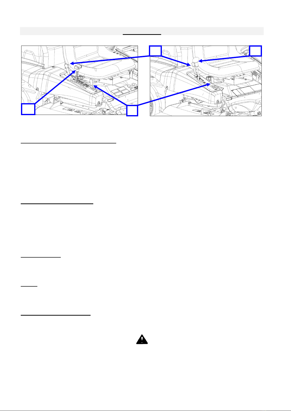
BRAKE PEDAL &LOCKING LEVER
Brake pedal is used in case of emergency or when parking brake
is locked (1,2, Figure 6).
To lock parking brake, press brake pedal, then push locking lever
(2) to the right. Depress the pedal, and after, the lever. To unlock
parking brake, press and depress brake pedal.]
(RM83G only)
Press the brake pedal (1, Figure 6) each time to change the
speed. When the brake pedal is pressed, brake works to stop
machine.
For your safety, always press the brake pedal first, then change
the speed lever position after the machine is stopped.
(RM830 only)
In the normal operation, use speed lever to stop the machine at
N position.
In case of emergency, press the brake pedal (1, Figure 6) to stop
machine, then speed lever returns to N position.
WARNING
Always inspect the brake before each use. If the brake is not properly adjusted, it may lead to
serious accident such as collision or fall. Press the brake pedal, then brake works to stop ma-
chine. When the brake pedal is pressed, it is possible to use locking lever (2, Figure 6) to lock
the parking brake. When brake pedal is further pressed, parking brake is unlocked. Engine
cannot be started when brake pedal is not pressed(locked).
WARNING
When leaving the machine be sure parking brake is locked, cutting blades are in off position
and ignition key is removed.
IGNITION KEY
Ignition key (3, Figure 6) is used to start and stop the engine.
When the key is in "stop", position the engine is stopped, the key can be removed. Turn the key
in this position when you want to stop the engine.
When the key is in "operation", position the engine can run, the key cannot be romoved in this
position
When the key is in "start", position the electric starting motor is engaged. When the engine has
started, release the key wich return in "operation", position.
STEERING WHEEL
The steering wheel(4, Figure 6) is used to allow the direction of the machine. Turn the steering wheel
to the right (clock wise) to go right and to the left to go to the left (anti-clockwise) Adjust the steering
wheel height (3 positions) by removing the pin (5, Figure 6). Adjust the steering wheel, and secure the
pin (5, Figure 6).
CAUTION
Always remove the key when machine is not used. When the engine is stopped, check than
the key is on "stop" position. Do not engage the electric starting motor more than 10 seconds.
If the engine has not start after 10 seconds, wait for 30 seconds before engage the electric
starting motor again.
WARNING
Use brake pedal in case of emergency only or to lock parking brake. If brake pedal is used at
high speed, the machine will stop suddenly.
1
5
2
4
3
Figure 6

OREC RM83G - © SAT 03/2015
11
WARNING
Do not let park the machine in slopes, do not move the travel lever when parking brake is
locked, this will damage the transmission. When leaving the machine be sure parking brake is
locked, cutting blades are in off position and ignition key is removed.
HEIGHT OF CUT CONTROL LEVER
The highest position of the lever (1, Figure
7) match to the transport position.
You can adjust the cutting height freely by
pressing the push button (2) and the lever
(1). When the lever position is high, the
height of cut is high, when lever position is
low, the height of cut is low.
WARNING
When cutting height is in low position, the machine needs stronger power, and spread more thrown
objects. Cutting low can cause damage to the machine and injury.
BLADE CLUTCH LEVER
Blade Clutch lever (3, Figure 7) make the engine drive the blade to mow. Pushing the lever forward
make the blade turning. Pulling the lever on reverse to stop the blade.
When using blade clutch lever, check that height of cut lever is in mowing position.
MOWING DECK SIDE SHIELDS
The mowing deck side shields should be unlock only to allow the machine to be loaded on a truck or a
trailer. This shields should be locked for mowing.
DANGER
The mowing deck side shields should be locked by bolt and nuts when mowing with the
machine. Check if guards and shield are locked by bolt and nuts before mowing with the
machine. If they are not locked, thrown object will cause injury and damage.
ENGINE
The mower is delivered with the owner’s manual of the engine. Read the engine manual before using
the machine.
DRIVING CLUTCH LEVER (RM830ONLY)
This lever (1, Fig 8) is used when the operator needs to move the
machine without the engine. The lever is located at the right front
side of operator sheet.
Put down the lever then move to neutral position « N » (Figure 8).
When machine pushed, the brake pedal must be released.
SAFETY SWITCHES
The OREC mower is equipped with safety switches :
To start the engine, followin 3 points need to be satisfied
- An operartor is seated
- Height of cut lever is in transport position.
- Blade clutch lever is disengaged.
When the engine is running, the operator leave the seat, the engine is cut off.
2
3
1
Figure 7
Figure 8
1
ON
OFF

OREC RM83G - © SAT 03/2015
12
WARNING
Never start the engine when operator is not seated in his place.
Do not dismount, cut off, unplug or shunt the safety switches.
If the engine is cut off by a safety switch put the ignition key in
"stop" position to avoid unloading of the battery
FUEL COCK
The machine is equipped with a fuel cock. This one is closed when the
lever is to the right and open when it is pushed to the left. (Figure 9, 1).
1
Figure 9

OREC RM83G - © SAT 03/2015
13
OPERATION
CAUTION
Check the tightening of bolts before use the machine, refering to the tightening torque charts.
The safety is one of our main worry when designing and manufacturing this machine.
Therefore, negligence in the use of the machine should reduce our efforts to nothing.
The prevention strictly depends on the care and on the skill of the user when applying
and maintening the machine.The best safety method remains a careful and skilled
user ; we wish you to be this kind of user.
The user of this machine is responsible for its safe use. He must be a skilled user specially trained for
the use of this machine. Read the safety instructions. This machine has been designed to mow grass.
It is not designed for any other operation. It is no designed to transport other tools or materials that
might damage it and cause injuries to the user. It must not be used to carry persons.
Never use the machine without having priorly carried out all the maintenance operations as
described in the daily maintenance chapter.
CAUTION
Never let children or unskilled persons use the machine. Check that nobody or no object
stands near the machine when at work. They could be hit by the moving parts.Nobody must
stand on the machine except the driver. Never put your hands under moving parts.
STARTING OF THE ENGINE
Turn the fuel cock "ON" and seat down at operator’s place.
Check that the cutting blade is disengaged, height of cut lever in transport position and speed
lever in neutral position « N ».
Push the throttle lever to the [ ] if engine is cold or push the throttle lever to [ ] if engine is hot.
Press the brake pedal and turn the key clockwise in start position. When the engine has started,
release the key and pull back the throttle lever to [ ]
MOWING
1. Adjust the height of cut control lever as needed.
WARNING
Do not forget that it is better to mow grass in several times. Cutting result is clear and efficient.
Remember that the machine is deteriorated rapidly in hot and dry weather. When the cutting
height is low, the blade may hit the ground and it causes damage to the blade. The user and
bystanders are likely to be injured by the thrown object, The thrown object cause damage to
their properties.
2. Push the throttle lever to have the engine running in the fastest speed. Then, slowly engage the
blade clutch lever in mowing position and go forward in the grass to mow.
3. Push slowly cutting blade control lever in engage position and go forward in the grass to mow.

OREC RM83G - © SAT 03/2015
14
WARNING
Engage the blade with engine at full speed gradually to avoid
damage to the belt.
The best cutting speed depends of quantity and the density of the grass.
Usually it is asked to mow in low speed. A tall grass will be cut slowly
and a low grass will be cut faster.
It is very dangerous to work in slope. Never work in slopes more than
15°.
WARNING
Check if there is nobody in the mowing path and especially in the thrown object zone (Figure 10).
Stop the machine immediatly when hitting something. Let the machine get cold, clean the machine from
dust and debris. Check the machine or ask your dealer to check if the machine is not damage.
HOW TO STOP THE MACHINE
Pull cutting blade clutch lever to the top in disengage position, pull height of cut lever to the top on
travel position.
(RM830) Hold down the lever to neutral position « N »
Press the brake pedal to stop the machine..
Turn off ignition key to stop position and remove it.
Lock the parking brake, and close fuel cock.
WARNING
Avoid parking the machine in slopes, park the machine in a flat hard area.
HOW TO CARRY THE MACHINE
Use a trailer or a truck which is enough for the load of the
machine. When loading the machine, use ramps able to resist
to 500 kg, 30 cm wide and equipped with unslipping surface.
Check the slope is not more than 16° (Figure 11).
LOADING :
Check cutting deck is disengaged and in travel position.
Lock the differential locking.
Approach the machine of the parralel ramp adjusted to the
track and locked to the truck.
Load the machine with engine at full rpm, slowly and with care.
When the machine is loaded, Turn off ignition key to stop position and remove it. Lock the parking
brake, and close fuel cock. Trim the machine with straps designed according to the weight of the
machine.
STORING THE MACHINE
Thoroughly clean the machine. Use touch up paint to prevent rust.
Check for worn and damaged parts, install new parts as required
Preform the normal maintenance of the machine according to maintenance chart.
Store the machine in a dry protected area
Remove ignition key.
Figure 10
Figure 11

OREC RM83G - © SAT 03/2015
15
MAINTENANCE OPERATIONS TO BE CARRIED OUT BY THE USER
IMPORTANT
BEFORE perform any maintenance operation on the machine, cut off the engine, disengage
the cutting blade. Lock the parkink brake and remove the ignition key. Do not let anybody
approach the driving place
If maintenance operation is not realized, damages can occur to the machine and personnal injuries to
the user and/or spectators. These damages and injuries will not be covered by the warranty.
Daily maintenance will be performed by the user.
Maintenance operations for first 20 hours, 100 hours and 300 hours should be realized by the
dealer.
Ask your dealer to check the machine if you meet some problems.
Ask your distributor the name of your dealer.
Daily maintenance
Transmission (gear) oil level (Figure 12a,b)
Check level with the machine cold on a flat surface. Oil level should reach the middle of the window (A). If
needed, add oil by this window. Drain oil by « B » plug.
Transmission Oil : “SAE 90” or “API Gl-5”
Quantity : 1.60L (RM83G) ,1.00L (RM830)
Transmission oil replacement frequecy
First replacement:
After 20 hours of operation
Later replacement:
Each 100 hours or Every year whichever comes first.
Figure 12a
Figure 12b
HST oil level (Figure 13)(RM830 ONLY)
Check level with the machine cold on a flat surface. Oil level should
reach the upper level "UP". If needed, add “VG46” or “SAE 10W30”.
Oil capacity: 0.50L
Check for oil leak.
Do not exceed upper level.
HST oil replacement (RM830 ONLY))
HST oil is clean when the unit is delivered. But when the unit is used
for a long time, the inside of HST unit will be dirty because there are
some sludges, and the oil is degraded. And dirty oil might disturb the
smooth working.
Replace HST oil frequently for your safety and smooth working.
Also replace oil filter when HST oil is replaced.
Figure 13
B
A
<<RM83G>>
<<RM830>>
B
C
A

OREC RM83G - © SAT 03/2015
16
Drain the used HST oil (RM830 ONLY)
1. Place the suitable container below the HST unit to catch the oil, then
remove the oil drain plug (A Figure 14).
2. Allow the used oil to drain completely, then reinstall the oil drain plug,
and tighten the oil drain plug securely.
3. With the HST unit on a flat surface, refill to the upper limit mark with
the recommended oil. (Refill same oil if possible.)
When oil is added, please pay high attention not to mix dust with oil.
Tighten the cap securely to prevent leakage.
Never loose the bolt (B Figure 14). Otherwise, it might influence for
machine driving. To do so is considered misuse, and damage caused
by misuse is not covered by Warranty.
Breeding the hydrostatic transmission system : (RM830 ONLY)
•After replacing the HST oil, some air can go in the
hydrostatic system. If there is air in the transmission
system, the driving is not perfect. Please do as following.
•Tilt the change lever by half to FORWARD and
BACKWARD for 10 seconds and then, return the
change lever to neutral position.(Figure 15)
*Please do above 2 works 5 times.
When tilt the change lever, throttle must be kept idling.
•And then, please make sure if there is no bubbles in the
HST oil tank.
•After working, please make sure if the oil level reaches
"High level position" in oil tank.
If not, please add oil up to "High level position" in oil tank.(figure 18)
HST oil replacement frequency
First replacement:
After 20 hours of operation
Later replacement:
Each 200 hours or Every year whichever comes first.
References: (The color of HST oil)
Color
Smell
Status
To do
Clean and no changing color.
Good
No foreign object
Use as usual
Clean, but there are some black points.
Good
Some foreign object
Use after filtering
Milky white
Good
Some water.
Change the oil
Black
Bad
Oxidated and degrade.
Change the oil
Fuel (Figure 16 and Figure 17)
•Check that the fuel tank level is full(1, Figure 1). Fuel level is full when the needle of the gauge
indicated « F ». Fuel level is emprty when needle of gauge indicate « E ». If fuel is empty, need to
load the fuel. Check that tank cap is fully closed, and check for leaks. Use only a good quality
gasoline(11.00L).
A
B
Forward
\
Backward
Throttle(Idling)
Figure 14
Figure 15
Figure 17
Figure 16

OREC RM83G - © SAT 03/2015
17
DANGER
Check that the fuel tank cap is closed properly, wipe leaky fuel before to start the machine.
Check there is no fire, electric sparks, cigarettes near the machine when refuelling.
When the machine is used on slopes, work with the fuel tank half full to avoid fuel leaking.
Remove flammable materials :
Remove flammable materials espacially near hot parts such as mufflers or engines.
It might cause fire.
Tires (Figure18)
Check the tires are not cutted, cracked or worn.
Check the pressure of the tires : 1,2 bar front and 1,4 bar
rear.
Safety stickers
Check the safety stickers are sticked at their location. Replace
them if they are worn and damage.
Latelal guards and shields
Check that the lateral guards and the shields are bolted.
Electrolyte battery level (Figure 19)
Check that the telectrolyte level is between the upper and
the lower level. Add distilled water as requiered.
DANGER
Be carefull when maintening the battery. Avoid flames, and
sparks. Always wear gloves and glasses. Wash with water
if you are hit by electrolyte.
Blade and blade holder condition
Check that the rotary blades are in a good condition, change
worn or damaged parts.
How to replace blades :
1. Remove the Blade by loosening the Hard Lock Nut.
Remove the Upper nut, and then remove the Lower nut.
2. After changing a new Blade (or to the reversed blade)
It also should be changed to a new Blade Bolt, Hard Lock Nut
and Nut Guard as shown by Figure 20.
CAUTION
The cutting blade can cut user’s hand. You can be cut and
injuried by cutting blade. Always wear gloves when holding
blades.
F
Too
high
OK
Too
low
Figure 18
Figure 19
Upper
Level
Lower
Level
Battery
TIRES PRESSURE
Upper
Nut
Lower
Nut
Hard Lock Nut
Nut guard
Blade
Stay
Blade
Blade set bolt
Knife collar
Figure 20

OREC RM83G - © SAT 03/2015
18
CAUTION
Only use the OREC original parts : “ non genuine ” parts will not assure you of a
correct and safe working. It is likely to make the warranty null and void.
Check the Blade Stay. Even if you do not see any bend or any abrasion on Blade Stay,
it should be replaced at every 100 hours or every 2 years of use.
Please check Blade frequently because it abrades early when you work at a place
including dry soil or sand.
We duly recommend you to purchase a spare Blade and a spare Blade Set Bolt in
advance and keep them at your hand.
When the Blade Set Bolt is worn on its head(1, Figure 21), it can cause a serious
accident with the blade thrown away. Replace the Blade Set Bolt immediately when
the dent disappeared. Also, Replace(or reverse) the blade when it is worn up to 30%
(Figure 21)
Lubrication :
Refer to Figure 22 to libricate the machine, Do not leave too much grease around the parts,
particularly when working in a sandy soil. Clean the grease nipples and lubricate the machine properly
(use a grease pump). Only use NLGI N°2 molybdenium bisulphide grease.
Air filter
Loosen the wing nut A, then remove the air filter (Figure 23). Blow the cartrige with low air pressure
from the inside to the outside oposite to the normal air flow. Change the cartridge if it is to dusty or
after some cleaning. Clean the foam with water and soap, dry it and oil with engine oil. Press it to
remove the oil in excess without squeezing it.
①
②
Figure 21
Figure 24
Figure 22
30%
30%
Figure 23
A

OREC RM83G - © SAT 03/2015
19
IMPORTANT
Do not blow at big pressure, and maintain a safe distance between the air nozzle and the
cartrige to avoid damage on it
Engine:
Refer to the engine manual delivered with the machine.
Oil level: check that the oil level and the engine is not hot by unscrew the
gauge A (Figure 25). The oil must be between the two marks “on the stick.
Drain the oil by the screw B.
Engine Oil: “SAE 10W30” or “API SL class”
Oil Quantity: 1.10L
Fuel filter
Check for water and dust in the fuel cartridge filter cock (C,
Figure 26). Clean if needed the filter inside the fuel cook.
Replace the filter if it is dirty.
Belt tension
Check for belt condition. If they are worn or cracked,
change by new one. (Figure 27)
If the blade brake tension is not enogh, move the
adjust nut in the direction of “A”
If the blade brake tension is too tight, move the
adjust nut in the direction of “B”
IMPORTANT
A bad tension belt makes sleeping and worning out very quickly. A too high tension of the belt
will damage the bearings.
C
A
Figure 25
Figure 26
Figure 27
A
B
Lock nut
Adjust nut

OREC RM83G - © SAT 03/2015
20
Brake
If the brake is not worked efficiently, tighten it with the nut
(B, Figure 28 / RM83G, C Figure 12b / RM830).
Tightening bolts
Check that the bolts, nuts…are properly tightened. The
vibrations tend to loosen the bolts.
Adjust safety switches
Ajust the screws for pushing the safety switches so they can
push switches from 3 to 5 mm.
Speed lever adjustment
Ajust the control link (A, Figure 29) in order to have the
machine staying still when the lever is at neutral.
DIFF LOCK LEVER ADJUSTMENT
Ajust the control wire (B, Figure 29) until the lever has
a free play of 1 to 3 mm before activate the diff lock.
Figure 28
Figure 29
B
A
This manual suits for next models
1
Table of contents
Other OREC Lawn Mower manuals