Origio Titan User manual

Titan Workstation
User Manual

Version 2.3 March 2019 • 2
INDEX
How To Use This Manual.......................................................................................................................................... 3
Introduction............................................................................................................................................................... 4
SAFETY INSTRUCTIONS........................................................................................................................................ 5
Before operation of the workstation.................................................................................................................... 5
INSTALLATION ........................................................................................................................................................ 6
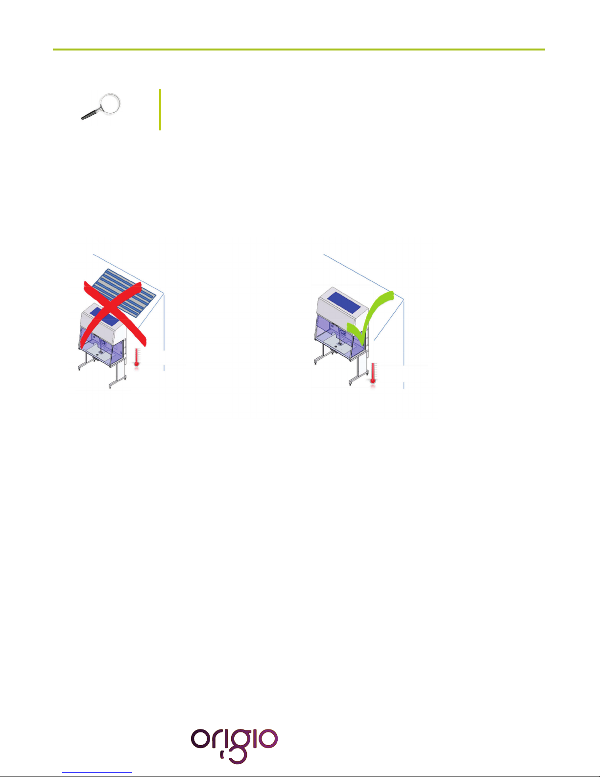
Device Placement .............................................................................................................................................. 6
AIR FLOW WORKING PRINCIPLE.......................................................................................................................... 7
CONTROL PANEL.................................................................................................................................................... 8
GENERAL OPERATING PROCEDURES ................................................................................................................ 9
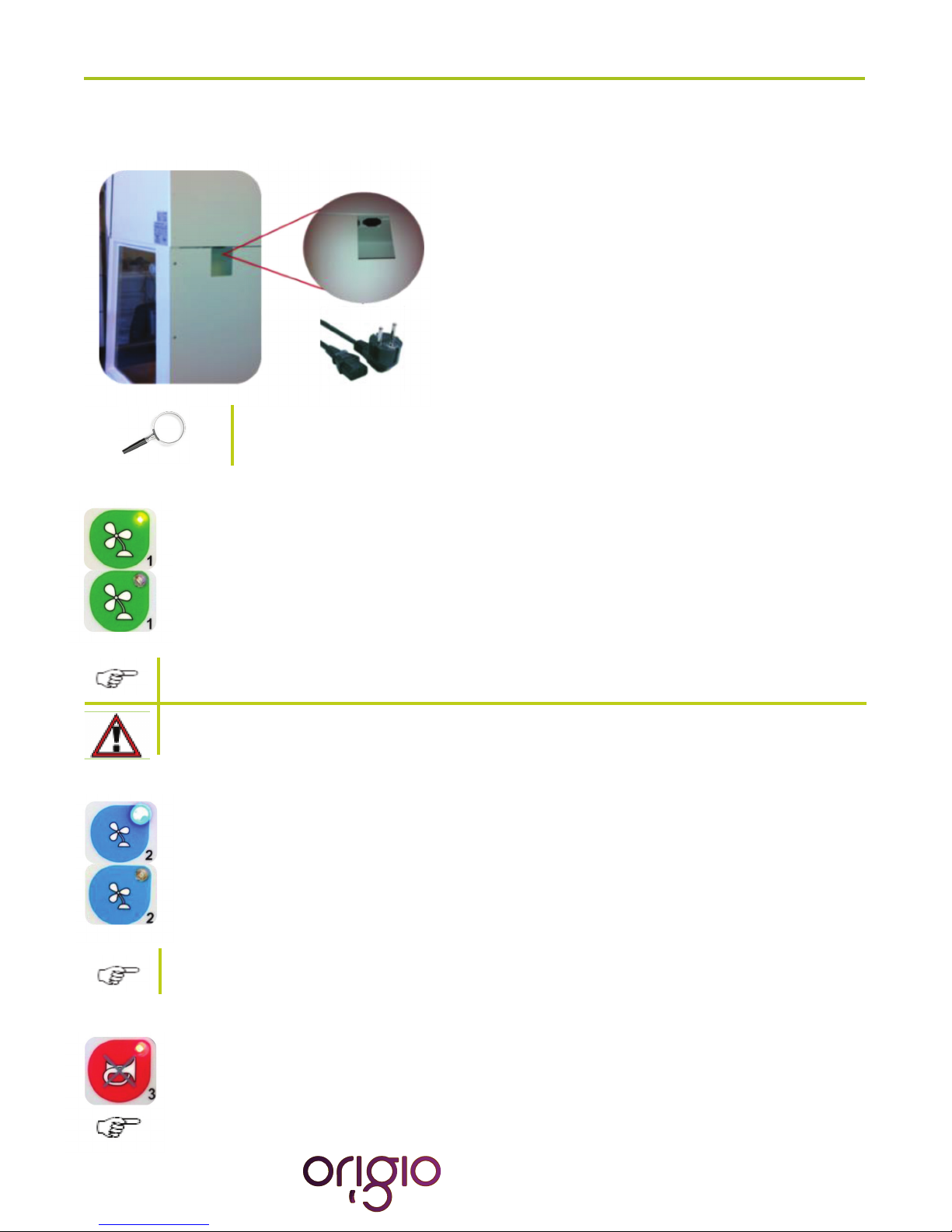
Connecting the power cord ................................................................................................................................ 9
Switching the Fans ON / OFF at Normal Speed ................................................................................................ 9
Switching the Fans ON / OFF at Reduced Speed.............................................................................................. 9
Alarm .................................................................................................................................................................. 9
Internal Light..................................................................................................................................................... 10
UV Light............................................................................................................................................................ 10
Working Heated Surface .................................................................................................................................. 10
CONTROL & PROGRAMMING.............................................................................................................................. 11
Overview of the Control Panel Menu................................................................................................................ 12
Generalairowinformation&counter ............................................................................................................. 12
Adjusting the level intensity of the internal light................................................................................................ 13
Programming and Controlling the UV light tlmer . ............................................................................................ 13
Programming Time and Date ........................................................................................................................... 16
Display Mode Functions ................................................................................................................................... 19
HEATED SURFACE ............................................................................................................................................... 21
Operational Characteristics .............................................................................................................................. 21
Temperature Controller..................................................................................................................................... 22
User Setup ....................................................................................................................................................... 23
Accessing the parameters and information menu ............................................................................................ 23
Resetting the THI and TLO recordings............................................................................................................. 23
Channel 1 set point .......................................................................................................................................... 23
Standby ............................................................................................................................................................ 24
Keypad lock...................................................................................................................................................... 24
Operating the heated areas.............................................................................................................................. 24
Normal Operation ............................................................................................................................................. 24
Checking the temperature ................................................................................................................................ 24
TROUBLESHOOTING Your Workstation ............................................................................................................... 25
TECHNICAL SPECIFICATIONS............................................................................................................................. 29
SPARE PARTS....................................................................................................................................................... 30
OPERATING THE STEREO MICROSCOPE HEATED GLASS AND LIGHT SOURCE CONTROLLER............... 31
OPERATING THE LCD MONITOR ........................................................................................................................ 36
WARRANTY AND LIABILITY ................................................................................................................................. 37
CUSTOMER SERVICE CONTACT INFORMATION .............................................................................................. 38

Version 2.3 March 2019 • 3
HOW TO USE THIS MANUAL
Warning, Cautions and important Notes
Throughout this manual, blocks of text may be accompanied with a pictogram. These blocks are WARNINGS,
CAUTIONS, and IMPORTANT NOTES and they are used as follows:
Symbols used in this Manual:
NOTE
Used to direct attention to a special item.
WARNING
DANGER
UV light radiation hazard. Use only with shielding in
place. Protect eyes and skin from exposure to UV light.
FURTHER INFORMATION
Further information is provided in other sections or
manuals.

Version 2.3 March 2019 • 4
INTRODUCTION
You are now in possession of a high quality microprocessor-controlled TITAN workstation
and it is designed to provide:
• Protection of the processed product against particle /microbiological contamination
• Heating control of the heated work area for sample handling
•GassingandHumidicationcontrol(Optional)
•Heatingcontrolofthelightopeningformorphologystudyundermicroscopy(Optional)
This user manual covers the following models:
• TITAN IVF
• TITAN LAF
The TITAN workstation has a built-in microprocessor controller featuring:
• LCD display indicating fan and alarm status.
• Air velocity sensors
•Clock(7days)andhour-counter.
• Pre-setting of automatic start-up and UV timer.
• Alarm for any deviation from safety conditions.
Furthermore, the TITAN workstation has the following characteristics:
• Negative pressure plenum for highest sample safety.
• Adjustable fan speeds.
•Workchamberwithtabletopinstainlesssteel(AISI304).

Version 2.3 March 2019 • 5
SAFETY INSTRUCTIONS
To avoid unintended or improper operation of the workstation, please read
this manual carefully
Before operation of the workstation
Before operating your workstation, please note the following:
The work chamber is to be carefully cleaned and/or disinfected. Use only hydrogen peroxide
(H2O2Solutions)orproductssuitabletobeusedinanIVFlab.NEVERuseammoniaor
chlorinated cleaners. It is recommended to use special lint-free wipes.
To ensure that the working area is clean and sterile the workstation fan must be run at normal
speed for at least 30 minutes prior to working inside the Workstation.
Objects and instruments must be carefully cleaned and/or disinfected before bringing them into
the work chamber.
Necessary instruments for use during work must be placed within reach to avoid unnecessary
movement inside the Workstation.
Forreliableoperationitisimportantthattheair-owconditionsareasunobstructedasmuchas
possible. Therefore, never overload the work chamber.
Putonnecessarypersonalclothingforreducingparticleemissionfromoperator(i.e.gloves,
masksandgeneralcleanroomclothing).Specialattentionshouldbegiventohandsandlower
parts of the arms, as these are the parts of the operator most likely to emit particles near the
product.
All work in the workstation must be performed with slow movements. Rapid arm movements in
the chamber may cause slipstreams, which will draw contaminated air into the work chamber.
Transportofpossiblycontaminatedmaterialmaycreateairowswhichcancontaminatethe
product.
The safety cabinet must not be used for working with materials which can cause allergic
reactions, or any harm to the health of the operator or the personnel. Attention is drawn to the
riskassessmentrequirementsoftheControlofSubstancesHazardoustoHealth(COSHH)
Regulations1999.(UK)
The cabinet is not suitable for HIGH-RISK biological agents. HIGH RISK biological agents
include all etiologic agents designated Class 4 by CDC, and oncogenic viruses classed high risk
byNCI.(USA)
Never operate the workstation cabinets if the fan compartment cover is removed. If this cover is
removed, the cabinet will give no protection of the operator or the environment and the fan will
run with openly rotating blades.
The workstation will not provide any protection for operator or environment against harmful
gases or vapors.

Version 2.3 March 2019 • 6
INSTALLATION
Please see the installation manual
Device Placement
The device should be placed on a level secure surface, away from heaters, coolers and air-conditioning outlets.
The device may only be operated at temperatures ranging between 15 °C and 35°C, with a maximum
80% relative humidity, and at normal air pressure.
Do not place under a HVAC outlet

Version 2.3 March 2019 • 7
AIR FLOW WORKING PRINCIPLE
Theverticalcleanaircabinetisaturbulence-free(laminar)verticaldisplacementowofclean
air in the work chamber protecting the product against particle contamination.
Filters:TheTITANworkstationmainlterisahigh-eciencyHEPAlterclass(H14)andthe
pre-lterofTITANisEU-3typetocapturedustparticlesforincreasedlifetimeoftheHEPA
lter.
Airvelocitymonitoring:Theturbulence-freeverticalowcanbemonitoredbymeansofanair
velocity sensor. Any deviation from safe conditions will be indicated visually and acoustically.

Version 2.3 March 2019 • 8
CONTROL PANEL
During normal use, the LED display shows the time and the day and the “Control and programming keys”
to navigate through the menu program. The numbers 0 to 9 in the control and programming keys are
for programming purposes.

Version 2.3 March 2019 • 9
GENERAL OPERATING PROCEDURES
Connecting the power cord
Connect the power cord to the mains power inlet.
The power inlet is located at the back of the workstation.
The power outlet must be grounded.
As soon as the device is connected an audible alarm will be
activated, an LED light will turn on and a message with
POWER UP ERROR will be activated on the control panel.
Pressthe“enter”buttontoswitchothealarmandtoreturn
to safe mode.
Please see the installation manual for further information.
Switching the Fans ON / OFF at Normal Speed
Press the “1- Fan Velocity” button to turn the fans ON. When activated a small green light on top
of the button will switch on.
Press the “1- Fan Velocity Button” to turn the fans OFF. When activated the small light on top of
the button will be OFF.
Topreventanyaccidentalswitchingonoroofthefan,thebuttonsfornormaland
reducedvelocitymustbeactivatedforatleast15secondsbeforetheytakeeect.
DO NOT WORK IN THE WORK SPACE AREA WHEN THE FANS ARE SWITCHED OFF
Switching the Fans ON / OFF at Reduced Speed
Press the “2- Fan Reduced Velocity” button to turn the fans ON. When activated a small blue
light on top of the button will switch on.
Press the “2- Fan Velocity Reduced Button” to turn the fans OFF. When activated the small light
on top of the button will be OFF.
WhenturningONthereducedspeedvelocity,theinternallightwillturnotoalert
the user. The internal light can be switched on again if needed.
Alarm
When an alarm is activated an audible acoustic signal is activated. On the control panel a small
red light is activated on the Alarm button. Press the Alarm Button to mute the acoustic alarm
signal.
The error causing the alarm will be explained on the LED display.

Version 2.3 March 2019 • 10
Whentheerrorhasbeenxedtheaudiblealarmandthesmallredlightareswitchedo.
MUTING THE ACOUSTIC SIGNAL WILL NOT SOLVE THE PROBLEM THAT
CAUSED THE ERROR
Internal Light
To switch ON the illumination light of the work chamber, press the “4-Internal Light” button.
When activated, a small blue light on top of the button will switch on.
To switch OFF the illumination light of the work chamber, press the “4-Internal Light” button
again. The small light on top of the button will be OFF.
To adjust the light intensity, refer to the section “Adjusting the level intensity
of the internal light”.
UV Light
The UV light and UV light timer are optional features.
For increased safety against unintended UV radiation which will harm eyes
and skin, use the timer to start the UV decontamination when no personnel
is present in the room where the workstation is located. Use the front shield
cover (Optional) to contain the radiation
To program the UV light time, refer to the section “Programming
and Controlling the UV light timer”.
To switch OFF the illumination light of the work chamber, press the “4-Internal Light” button
again. The small light on top of the button will be OFF.
To switch ON the UV light for decontaminating the work chamber, press the “5- UV Light” button.
When activated a small yellow light on top of the button will switch on
Working Heated Surface
To operate the heated work area, refer to the section “Heated Surface”.
ToswitchONtheORIGIOLightSourceandtheworkingheatedsurface(s),pressthebutton.
When activated a small blue light on top of the button will switch on. This button simultaneously
activatestheworkingheatedsurface.(NotethisfeatureisnotavailableontheFORTUNAICSI
models)
ToswitchOFFtheworkingheatedsurface(s),pressthebuttonagain.Thesmalllightontopofthe
button will be switched OFF.

Version 2.3 March 2019 • 11
CONTROL & PROGRAMMING
Thissectiondescribeshowtoaccessthedierentmenusandhowtocontrolandtoprogramsomethefeatures
oeredwithyourworkstation.TheControl&Programmingmenuofyourworkstationcontainsthefollowing:
Standard display
Adjusting the intensity of the internal light
Programming and controlling the UV light timer
Setting the internal clock
Adjusting display settings
Programmingandcontrollingtheautomaticstartandshut-oofthefan
Entering the service mode

Version 2.3 March 2019 • 12
Overview of the Control Panel Menu
CONTROL PANEL MENU
General air ow information & counter
This section describes how to access information about the running hours of the fan. The fans are designated
FLOW 1, FLOW 2.
To learn how to enable and disable these functions refer to the section
“Programming the Air Flow to Auto Start”.
Standard display

Version 2.3 March 2019 • 13
Press the right or left arrow button to navigate towards the FLOW information.
SCANLAF with FLOW 1 will be displayed together with a value. This value is for
internal service information.
Press the right or left arrow button to navigate towards the FLOW information.
SCANLAF with FLOW 2 will be displayed together with a value. This value is for
internal service information.
Press the right or left arrow button to navigate towards the FLOW information.
SCANLAF with FLOW 3 will be displayed together with a value. This value is for
internal service information.
Press the right or left arrow button to navigate towards the FLOW information.
SCANLAF with FAN HOUR will be displayed together with a value. This value is the
number of hours the fan has been running.
Standard display
Press the “enter” button to enter the menu.
The USER MODE with the “LIGHT LEVEL” will be displayed together with a
representationofthe“Control&ProgrammingKeys”.Therstlinewiththearrow
symbol “ ”enables the user to go back to the previous menu or to move to an-
other function. The symbol “o” represents the “ENTER” button.
Press the “enter” button to validate your choice.
The LIGHT LEVEL and “NIVEAU: 100 % will be displayed together with a
representation of the Control & Programming Keys
Press the up or down arrow. The level of intensity will go up or down. Repeat
pressing the arrow until you reach the level of intensity desired. If you hold down
the arrow, the light intensity will change more rapidly.
Press the “enter” button to validate and to return to the MENU or wait a few seconds
and the display will return by itself to the standard display
Adjusting the level intensity of the internal light
This section covers how to adjust the light intensity of the internal light of the workstation.
Programming and Controlling the UV light timer
This section describes how to program the UV light timer.

Version 2.3 March 2019 • 14
Note:Forthisfeaturetoworkcorrectly,youmustsetupthedateandtimerst.
This is described in the section “Programming Time and Date”
Unintended UV Radiation will harm eyes and skin. For protection, use the tim-
er to start the UV decontamination when not present in the workstation area.
Use the front shield cover (optional) to contain the radiation.
Standard display
Press the “enter” button to enter the menu.
Press on the right arrow button to enter the next menu.
The USER MODE with the “UV CONTROL” will be displayed together with a repre-
sentationofthe“Control&ProgrammingKeys.Therstlinewiththearrowssym-
bol “ ”enables the user to go back to the previous menu or to move to another
function. The symbol “o” represents the “enter” button.
Press the “enter” button to validate your choice.
The UV AUTOSTART with START: OFF will be displayed.
Press the up or down arrow to change the settings between START: OFF, TODAY
and START: AUTO.
If you wish to program the UV light to start today, use UV AUTOSTART TODAY.
IfyouwishtoprogramtheUVlighttostartonadierentday,useUVAUTOSTART
START: AUTO.
Press the “enter” button to enter the menu.
The UV AUTOSTART and “ON TIME: 00:00” will be displayed. This is the time at
which the UV light should start
Press the “enter” button to validate your choice.
Therstdigitofthehourwillbeblinking.Toenterthehourpresstheappropriate
number found on the control panel. Continue this operation for the hours and the
minutes. This will indicate the Time when the UV Light will switch ON automatically.
Press the “enter” button to validate your choice.
UV Autostart Option Selected: “TODAY”

Version 2.3 March 2019 • 15
The UV AUTOSTART and “OFF TIME: 00:00” will be displayed. This is the Time at
whichtheUVLightwillswitcho.
Press the “enter” button to validate your choice.
Therstdigitofthehourwillbeblinking.Toenterthehourpresstheappropriate
number found on the control panel. Continue this operation for the hours and the
minutes. This will indicate the time when the UV light will turn OFF automatically.
Press the “enter” button to validate your choice.
Note:Forthisfeaturetoworkcorrectly,youmustsetupthedateandtimerst.How
to do this is described in the section “Programming Time and Date”
Press the “enter” button to enter the menu.
The UV AUTOSTART and “ON TIME: 00:00” will be displayed. This is the time at which
the UV light should start.
Press the “enter” button to validate your choice.
Therstdigitofthehourwillbeblinking.Toenterthehourpresstheappropriate
number found on the control panel. Continue this operation for the hours and the
minutes. This will indicate the time when the UV Light will switch ON automatically.
Press the “enter” button to validate your choice.
The UV AUTOSTART and “OFF TIME: 00:00” will be displayed. This is the Time at
whichtheUVLightwillswitcho.
Press the “enter” button to validate your choice.
Therstdigitofthehourwillbeblinking.Toenterthehourpresstheappropriate
number found on the control panel. Continue this operation for the hours and the
minutes. This will indicate the time when the UV light will turn OFF automatically.
Press the “enter” button to validate your choice.
The Week display will appear “ M T W T F S S”
Press the “enter” button to validate your choice.
The Monday option will be blinking.
UV Autostart Option Selected: “AUTO”

Version 2.3 March 2019 • 16
Press on the UP arrow to select Monday. Press the right and left arrows to navigate
between the days,
In this example the Monday option will be marked with an “X” to indicate that the
UV light will be ON on Monday at the desired time and will be switched OFF at the
desired time programmed earlier in this section.
Pressonthe“enter”buttontoconrm
Press the “enter” button to enter the menu.
Press the right or left arrow button to reach the menu displaying “SET WATCH”.
The USER MODE menu with SET WATCH will be displayed together with a
representation of the “Control & Programming keys”.
Press the “enter” button to enter the menu.
The SET WATCH menu with FORMAT: 12H or 24H will be displayed together with a
representation of the “Control & Programming keys”
Press on the DOWN or UP arrows to change the settings from 12H to 24H and
vice versa.
Press the “enter” button to enter the menu.
The SET WATCH menu with TIME will be displayed.
Therstdigitofthehourwillbeblinking.Toenterthehourpresstheappropriate
number found on the control panel.
Example: Setting up the watch at 16:39
Press the button that has the number 1 and it will be registered on the display.
The second digit of the hour will be blinking.
Press the button that has the number 6 and it will be registered on the display.
Continuethistolloutalldigits.
Press the “enter” button to enter the menu, and press the right or left arrow buttons to
reach the menu displaying “SET WATCH”
Programming Time and Date
This section describes how to set the time and the date.

Version 2.3 March 2019 • 17
TheSETWACHmenuwiththeday’srstletter“MTWTFSS”willbedisplayed.
Press on the RIGHT or LEFT arrow button to navigate to the correct day.
Press the “enter” button to validate your choice.
The SET WACH menu with DATE will be displayed. The Date has the format of
DD / MM/ YY.
Press the RIGHT arrow button to navigate to the day, month or year section. Use the
same method for setting the time to enter the date.
Press the “enter” button to enter the menu.
Press the RIGHT or LEFT arrow button to reach the menu displaying
“FAN CONTROL”
The USER MODE menu with FAN CONTROL will be displayed together with a repre-
sentation of the “Control & Programming Keys.
Press the “ENTER” button to enter the menu.
The FAN AUTOSTART and “START: OFF” will be displayed.This indicates that the
auto start function is disabled.
Press Down or UP to change the settings. Two options can be selected FAN
AUTOSTART: TODAY, or, FAN AUTOSTART: START:AUTO.:
The FAN AUTOSTART and “TODAY” indicate the auto start function can be
programmedforthecurrentdayataspecictime.
The FAN AUTOSTART and “START: AUTO” indicate the auto start function can be
programmed any given day and time.
Press the “enter” button to enter the menu.
Programming the Air Flow to auto start (Weekly or Daily)
Thissectiondescribeshowtoenableandprogramtheairowtoautostartonaspecicdateandtime,andhow
to disable that feature.
Option selected: TODAY

Version 2.3 March 2019 • 18
The FAN AUTOSTART and “ON TIME: 00:00” will be displayed. This is the time at
which the fans should start.
Press the “enter” button to enter the menu.
Therstdigitofthehourwillbeblinking.Toenterthehourpresstheappropriate
number found on the control panel. Continue this operation for the hours and the
minutes. This will indicate the time when the fan will turn ON automatically.
Press the “enter” button to validate your choices.
The FAN AUTOSTART and “OFF TIME: 00:00” will be displayed. This is the time at
whichthefanswillturno.
Press the “enter” button to enter the menu.
Therstdigitofthehourwillbeblinking.Toenterthehourpresstheappropriate
number found on the control panel. Continue this operation for the hours and the
minutes. This will indicate the time when the fan will turn OFF automatically.
Pressthe“enter”buttontoconrmyourchoices.
Note:Forthisfeaturetoworkcorrectly,youmustsetupthedateandtimerst.How
to do this is described in the section “Programming Time and Date”
Press the “enter” button to enter the menu.
The FAN AUTOSTART and “ON TIME: 00:00” will be displayed. This is the time at
which the fans should start.
Press the “enter” button to enter the menu.
Therstdigitofthehourwillbeblinking.Toenterthehourpresstheappropriate
number found on the control panel. Continue this operation for the hours and the
minutes. This will indicate the time when the fan will turn ON automatically.
Press the “enter” button to validate your choices.
The FAN AUTOSTART and “OFF TIME: 00:00” will be displayed. This is the time at
whichthefanswillturno.
Option selected: AUTO

Version 2.3 March 2019 • 19
Press the “enter” button to enter the menu.
Therstdigitofthehourwillbeblinking.Toenterthehourpresstheappropriate
number found on the control panel. Continue this operation for the hours and the
minutes. This will indicate the time when the fan will turn OFF automatically.
Pressthe“enter”buttontoconrmyourchoices.
The Week display will appear “ M T W T F S S”
Press the “enter” button to validate your choice.
The Monday option will be blinking.
Press on the UP arrow to select Monday or press the right and left arrows to navigate
between the days,
In this example the Monday option will be marked with an “X” to indicate that the fan
will be ON, on Monday at the desired time and will be switched OFF at the desired time
programmed earlier in this section.
Pressonthe“enter”buttontoconrm
Press the “enter” button to enter the menu.
Press the RIGHT or LEFT arrow button to reach the menu displaying
“DISPLAY MODE”
The USER MODE menu with DISPLAY MODE will be displayed together with a
representation of the “Control & Programming Keys”.
Press the “enter” button to enter the menu.
The DISPLAY MODE and “FLOW: ON” will be displayed together with a representation
of the Control & Programming Keys.
Press the up or down arrow to select the between up or on mode. This feature will
disable the view of the information on FLOW 1, FLOW 2 AND FLOW 3
Display Mode Functions
This section describes how to enable and disable the Flow and Fan information presented in the overview of the
control panel menu.

Version 2.3 March 2019 • 20
Press Enter to validate. The display will return to DISPLAY MODE.
Press the “enter” button to enter the menu.
Press the DOWN or UP arrow to reach the following display:
The DISPLAY MODE and “TIME OUT” will be displayed together with a
representation of the Control & Programming Keys.
Press the “ENTER” button to enter the menu to turn this function ON or OFF.
Turning this function OFF will disable the following display and return to
DISPLAY MODE.
Press the “enter” button to enter the menu.
Press on the DOWN or UP arrow to reach the following display:
The DISPLAY MODE and “TIME OUT: 005 SEC” will be displayed. This
feature indicates that any information or changes will remain displayed for
5 seconds before returning to the Standard Display. The display time is of a
minimum of 5 seconds and therefore can only be increased. To increase the
duration of the displayed information use the UP and DOWN arrows.
Table of contents
Other Origio Desktop manuals
Popular Desktop manuals by other brands

Commodore
Commodore Plus/4 Unpacking and Setting Up

kupper
kupper 70425-2 Assembly instruction

Kontron
Kontron KBox B-202-CFL user guide

Dell
Dell INSPIRON 530s Series Setting up

Dell
Dell OptiPlex 780 SFF Setup and Features Information Tech Sheet

Lenovo
Lenovo IdeaCentre Q200 Hardware hardware replacement guide