8 IM0973290 R1-3
Installation manual
5. Disposal
Disassembly, removal and disposal. Local regulations for
dealing with waste must be followed when disposing of
disassembled components or entire units.
6. General terms and conditions
Orlaco Products BV is not liable for damage resulting from
inadequate servicing, incorrect usage or alterations made
to the equipment without informing the manufacturer in
writing.
This installation manual has been made available by Orlaco
Products BV. All rights reserved. No part of this manual
may be reproduced and/or made public in printed form, in
photocopy form or on microfilm, or in any other way, with-
out the prior written permission of Orlaco. This also applies
to the associated drawings and figures.
Orlaco reserves the right to make changes to components
at any time without informing customers beforehand or
directly. All dimensions given are for commercial purposes.
For information regarding repairs that is not covered in
this manual, please contact the Orlaco Products BV service
department.
This manual has been prepared with all due care and
attention. However, Orlaco Products BV cannot be held
responsible for any errors in this manual or any conse-
quences thereof.
7. Version details
Version R1-0. First issue, February 2013
Version R1-1 Chapter 4, Table “orange wire” changed, June 2013.
Version R1-2 Chapter 1, text changed and denomination added, December 2013.
Version R1-3 Barcode added, September 2015.
IM0973290 R1-3 5
PART A
1
16
5
4
7
16
7
8
013
12 16
PART B
PART C PART D
12 12
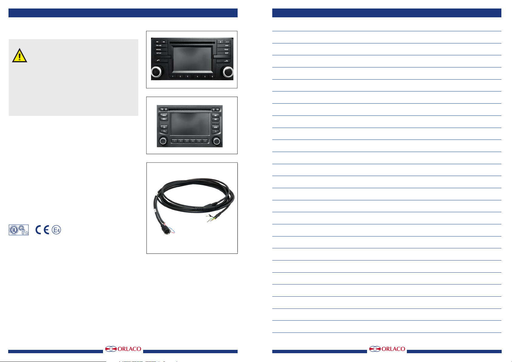
Fit the supplied Orlaco cable, crimp contacts are pre-
assembled.
Please ensure that these contacts are pressed into the
plastic plug correctly; so that the locking clicks.
White -- Coax core on D3
Blue -- Shielding coax on D4
For DAF and Scania ensure that the control wire to D6 is
connected!
Orange-- Control camera on/off at D6(reverse)
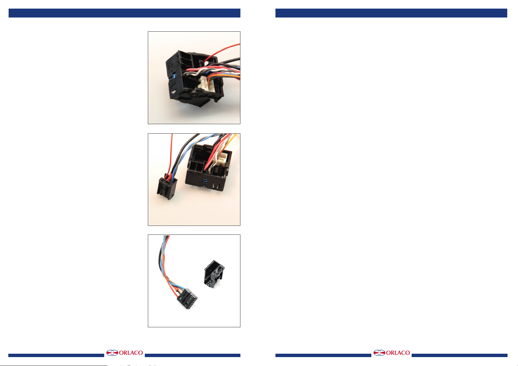
For MAN ensure that the control wire runs through the CTS
connector.
This is in C connector on pin 1, C1 (CTS).
The method is equal to the previous one.
The cable Art. No.: 0303090 is useful on any vehicle,
providing that the switching voltage is 7 volts.
The cable is only suitable for rear view.
3. Multi camera system
If a multi camera system is used; please contact Orlaco
Products BV.
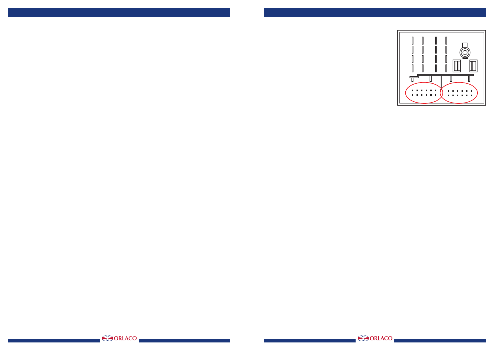
Figure 7
Installation manual