IG-136-EN version 13; 23/04/2020 3
General Instructions
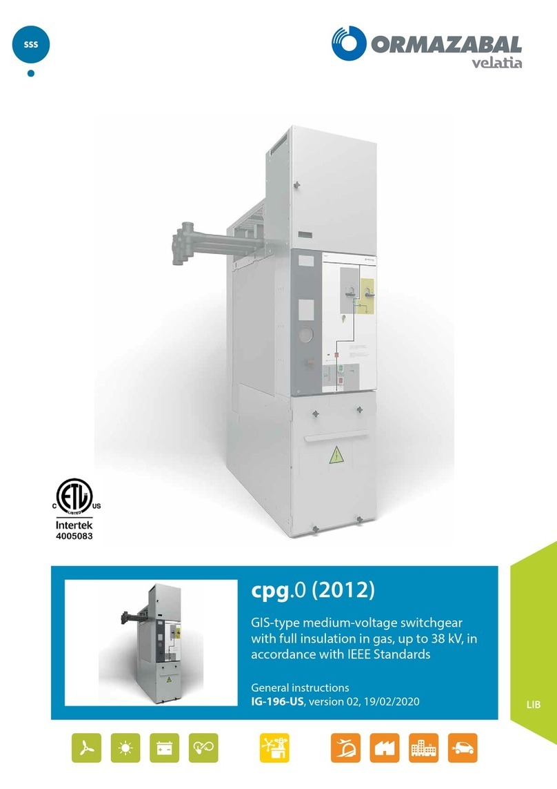
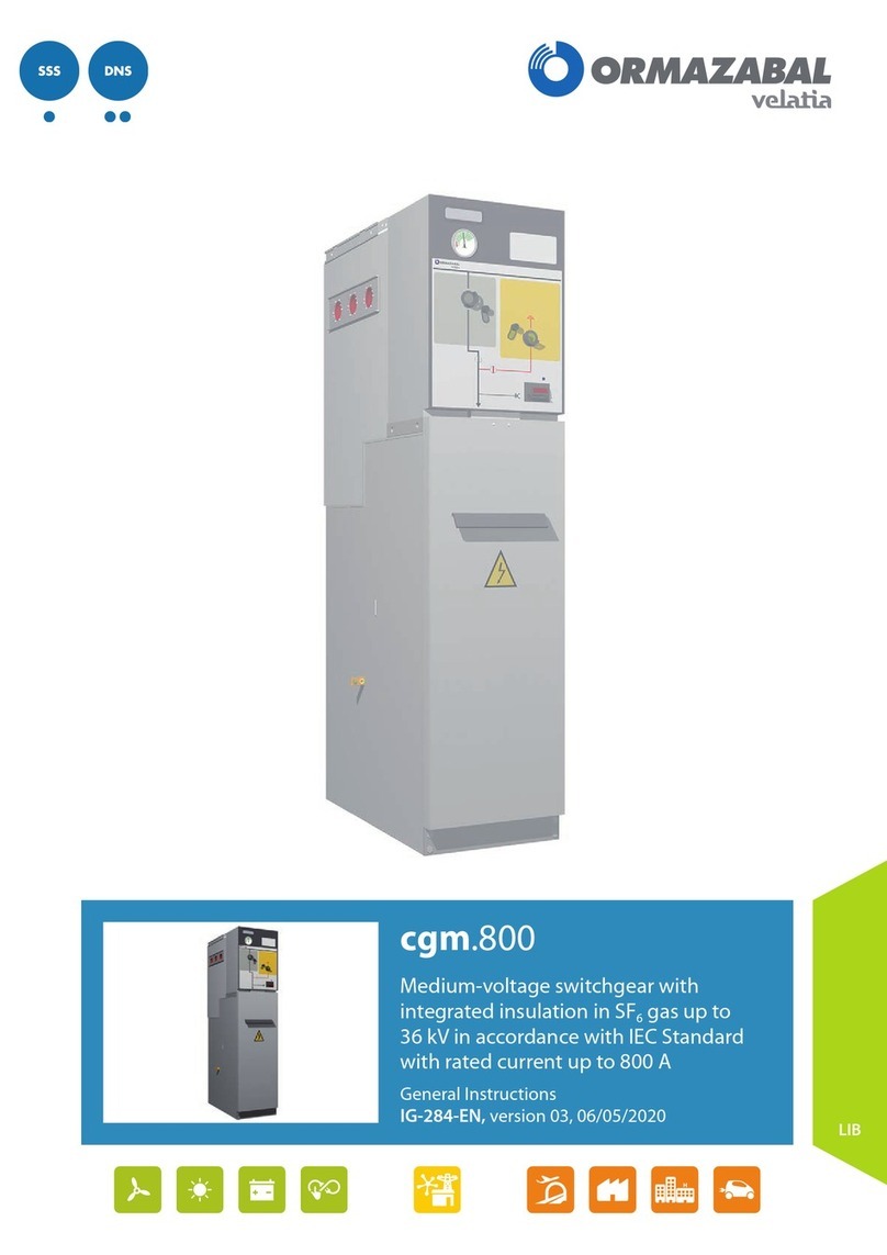
cgm.3 system: Medium-voltage cubicles with integrated
insulation in SF6gas up to 40.5 kV in accordance with
IEC Standard with rated current up to 630 A.
Contents
Contents
1. General description ...................................................5
1.1. Models ......................................5
1.2. Standards applied............................5
1.3. Main components ...........................6
1.3.1. Gas tank .....................................7
1.3.2. Driving mechanisms compartment ...........7
1.3.3. Base .........................................8
1.3.4. Name plate ..................................9
1.4. Ratings table................................10
1.5. Dimensions and weights ....................11
1.6. Operating conditions .......................12
2. Handling and transport...........................................13
2.1. Lifting methods.............................13
3. Storage......................................................................15
4. Installation ...............................................................16
4.1. Unpacking the equipment ..................16
4.2. Positioning accessories during transport.....16
4.3. Minimum installation distances..............17
4.4. Recommended cable connection trenches...18
4.4.1. Cubicles with internal arc in tank up to
20 kA - 0.5 s .................................18
4.4.2. Cubicles with Internal arc classification
IAC up to 25 kA - 1 s .........................21
4.5. Floor fastening..............................26
4.5.1. Floor fastening on profile....................26
4.5.2. Floor fastening by anchoring ................26
4.6. Connecting the cubicles.....................31
4.7. Earthing the switchgear .....................31
4.8. Cable connections ..........................32
4.8.1. Horizontal front connection .................33
4.8.2. Cable connection in fuse protection
function 1400 mm high .....................35
4.9. Assembling and connecting metering
transformers in cgm.3-m . . . . . . . . . . . . . . . . . . . .37
4.10. Assembling and connecting metering and
auxiliary services transformers in cgm.3-ma..37
5. Recommended sequence of operations.................38
5.1. Checking the gas pressure ..................38
5.2. Live voltage indicator .......................39
5.3. Phase concordance check ...................40
5.4. Feeder function.............................41
5.4.1. Mimic diagram..............................41
5.4.2. Actuating levers ............................41
5.4.3. Opening operation from earthing position...42
5.4.4. Switch closing operation from isolating
position ....................................43
5.4.5. Opening operation from closed position.....44
5.4.6. Earthing operation from open position ......45
5.4.7. Cable test...................................46
5.5. Busbar switch function ......................47
5.5.1. Mimic diagram..............................47
5.5.2. Actuating lever .............................47
5.5.3. Switch closing operation from isolating
position ....................................48
5.5.4. Opening operation from closed position.....49
5.6. Busbar switch function with earth
connection .................................50
5.6.1. Mimic diagram..............................50
5.6.2. Actuating lever .............................50
5.6.3. Opening operation from earthing position...51
5.6.4. Connecting the switch-disconnector from
isolating position ...........................52
5.6.5. Opening operation from closed position.....53
5.6.6. Earthing operation from open position ......54
5.7. Busbar rise function with earth connection ..55
5.7.1. Mimic diagram..............................55
5.7.2. Actuating lever .............................55
5.7.3. Earthing switch opening operation ..........56
5.7.4. Earthing switch closing operation ...........57
5.8. Fuse protection function ....................58
5.8.1. Mimic diagram..............................58
5.8.2. Actuating lever .............................58
5.8.3. Opening operation from earthing position...59
5.8.4. Spring charge operation and closing of the
switch-disconnector from isolating position .60
5.8.5. Opening operation from switch-disconnector
closed position .............................61
5.8.6. Earthing operation from open position ......62
5.9. Fuse replacement sequence .................63
5.9.1. Selection of recommended fuses ............66
5.10. Circuit-breaker function with AV/RAV driving
mechanism .................................67
5.10.1. Mimic diagram..............................67
5.10.2. Spring charge and actuating levers ..........68
5.10.3. Opening operation from earthing position...68
5.10.4. Closing operation from isolating position ....70
5.10.5. Opening operation from closed position.....72
5.10.6. Earthing operation from open position ......74
6. Safety elements........................................................76
6.1. Acoustic earthing prevention alarm .........76
6.2. Interlocks ...................................76
6.2.1. Locking with a padlock......................77
6.2.2. Locking with a lock..........................77
