1. Applicable documents
All available documents on the product www.festo.com/pk
Motor operating instructions
Shaft operating instructions
2. Safety instructions and notes on mounting
Switch off power supply before mounting work.
Observe the safety information (Applicable documents).
Clean shafts. The spring pins 3/4only grip efficiently on dry and grease-
free drive shafts.
Each time after disconnecting or turning the motor, perform a homing
procedure.
Observe tightening torques. Unless otherwise specified, the tolerance is
±20 %.
3. Intended use
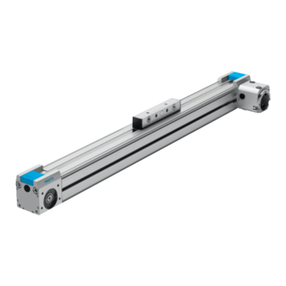
Parallel kit EAMM-U-...-D...-...A/P/R-S1:
Connection of an axis to a motor in a parallel configuration that fulfils degree
of protection IP65 (Section 14).
4. Further information
Accessories www.festo.com/catalogue
5. Scope of delivery
5a. Parallel kit EAMM-U-...-D...-...A/P/R-S1
15980d_1
1Lower part
2Screw
3Axis clamping sleeve
4Motor clamping
sleeve
5Toothed belt
6Toothed belt pulley
7Upper part
8Screw
9Square nut1)
aJ Screw
aB Blanking plug2)
aC Adapter plate3)
aD Screw3)
aE O-ring axis4)
aF Sealing ring for aJ
aG Motor seal
aH Seal for aC5)
aI Sealing ring for 2
bJ Seal for 7
bB Seal for aC3)
bC O-ring motor3)4)
(1x)
(4x)
(1x)
(1x)
(1x)
(2x)
(1x)
(7x)
(4x)
(4x)
(1x)
(1x)
(4x)
(1x)
(4x)
(1x)
(1x)
(4x)
(1x)
(1x)
(1x)
1)2)
1) For EAMM-U-...-42A-S1, the mounting direction of the screws 2differs. Attach the lower
part 1to the motor by using the screws 2and sealing rings aI. The square nuts 9are not
required.
2) For EAMM-U-110/-145, the blanking plug aB is included in the scope of delivery
5b. Accessories (not included in delivery)
15346d_13
dA Lubricating grease
LUB-KC1
(silicon-free)
dB Clamping element6)
EADT-E-U1-110
(1x)
(1x)
6. Mounting the lower part
1598
0d_2
0
Push the O-ring aE onto the
centring collar on the drive
cover of the axis.
1598
0d_2 Place sealing rings aF onto
the screws aJ.
Fasten the lower part 1to
the axis by using the
screws aJ7).
1598
0d_3
0
With seal aH5):
Place the seal aH in the
recess of the lower part 1.
Check: The notches (X) in the
seal aH are located over the
drill holes (Y).
1598
0d_3
6
With adapter plate aC3):
Place O-ring bC into the slot
of the adapter plate aC.
Fasten the adapter plate aC
to the motor with the
screws 2.
1598
0d_3
7
Position the seal bB on
the adapter plate aC.
Attach the motor to the
lower part 1via the
adapter plate aC and the
seal bB by using the
screws aD.
Check: The motor can be
moved in the elongated holes.
1598
0d_2
7
Without adapter plate aC3):
Place the seal aG onto the
motor flange.
15980d_3
Place sealing rings aI onto
the screws 2.
Attach the motor to the
lower part 1by using the
screws 2and square
nuts 91).
Check: The motor can be
moved in the elongated holes.
3)4)5)6)7)
3) For EAMM-U-...-67A, the adapter plate aC, screws aD, seal bB and O-ring bC are included
in the scope of delivery.
4) To distinguish between the O-rings aE and bC:Section 13.
5) The seal aH is included in the scope of delivery for motor interface 100A.
6) For EAMM-U-110/-145, the clamping component dB is needed as a tool.
7) If the tightening torques are exceeded, the cover screws of the axis will loosen during
disassembly.
7. Mounting the toothed belt
15980d_4
Move the motor in the
direction of the axis as far as
its stop.
Grease the spring
pins 3/4on the thread
and the outside of the cone
with lubricating grease dA.
Greased spring pins 3/4 can
be tightened evenly.
Screw the spring pins 3/4into the threads of the toothed belt
pulleys 6. Do not tighten.
Insert the toothed belt pulleys 6into the toothed belt 5.
Place the spring pins 3/4onto the drive shafts.
Information
The position of the surface (A) depends on the size.
50/60 70/86 110/145
15346d_9
15980d_19
Position surfaces (A) approx. 1 mm above the reference surface (B).
Background: The tooth belt pulley 6moves inwards when tightening.
15980d_5
Select the required tightening torque for the toothed belt pulleys 6
(Section 10).
Tighten the toothed belt pulleys 6. Apply counter pressure to the
spring pins 3/4.
Check: The surfaces (A) of the toothed belt pulleys 6are flush with the
reference surface (B) (tolerance: ± 0.5 mm).
15980d_8
Note
Comply with the tolerance.
If the toothed belt 5or one of the toothed belt pulleys 6is grinding against
the housing:
Unscrew the spring pin 3/4slightly.
Readjust the toothed belt pulleys 6.
8. Tensioning the toothed belt
Note
A low toothed belt pretension is recommended.
Excessive toothed belt pretension can cause:
–impermissible radial loads/breaking of the shafts
–increased wear of the toothed belt 5and the bearings of the axis and
motor.
Avoid excessive toothed belt pretension.
The toothed belt 5is tensioned when the strands (C) run approximately
parallel.
Untensioned: y ,x Tensioned: y L1 … 1.05 x
15346d_22
8a. For EAMM-U-50/-60/-70/-86
Move the motor by hand until the clamping force Fv is exerted on the
toothed belt 5(Table).
Tighten screws 2.
8b. For EAMM-U-110/-145
1534
6d_1
8
Place the clamping
element dB into the drill
hole (D) in the lower part 1.
Tighten the clamping
element dB with a hex
wrench (ß8). Observe the
recommended torque
(Table).
Tighten screws 2.
1534
6d_1
7
Press the blanking plug aB
into the drill hole (D).
EAMM-U- Recommended torque Clamping
force Fv
dB [Nm] 5[N]
15346d_24
15346d_25
15346d_23
50 −−−15 … 35
60 −−−40 … 70
70 −−−60 … 110
86 −−−70 … 130
110 0.2 … 0.6 0.4 … 0.8 0.6 … 1.0 120 … 300
145 1.0 … 1.5 1.5 … 2.0 2.0 … 2.5 200 … 450
Continuation on the reverse side!
Assembly instructions (Original instructions)
8064090
1704d
[8064092]
†‡
Parallel kit
EAMM-U-...-D...-...A/P/R-S1
Festo AG & Co. KG
Ruiter Straße 82
73734 Esslingen
Germany
+49 711 347-0
www.festo.com

