Orsys MICRO-LINE C6713Compact-2 Operating and maintenance manual

HARDWARE REFERENCE GUIDE
MICRO-LINE®C6713Compact-2
Date : 11 April 2012
Doc. no. : C6713Cpt-2_hrg
Iss./Rev : 1.0
Page : 1
Orsys Orth System GmbH, Am Stadtgraben 25, 88677 Markdorf,Germany http://www.orsys.de
Hardware Reference Guide
micro-line®C6713Compact-2
High performance DSP / FPGA / IEEE 1394 board

HARDWARE REFERENCE GUIDE
MICRO-LINE®C6713Compact-2
Date : 11 April 2012
Doc. no. : C6713Cpt-2_hrg
Iss./Rev : 1.0
Page : 2
Contents
1PREFACE......................................................................................................................6
1.1 History ..................................................................................................................................... 7
2HARDWARE OVERVIEW ............................................................................................. 8
2.1 Block Diagram of the C6713Compact-2 ............................................................................... 8
2.2 Connectors ............................................................................................................................. 9
2.2.1 micro-line®Connector............................................................................................................ 9
2.2.2 JTAG Connector..................................................................................................................10
2.2.3 IEEE1394 Connectors......................................................................................................... 10
2.3 Interfaces and Hardware Components............................................................................... 10
2.3.1 FPGA................................................................................................................................... 10
2.3.2 IEEE1394 Interface .............................................................................................................12
2.3.3 External Memory (on-board SDRAM).................................................................................. 12
2.3.4 Flash Memory...................................................................................................................... 13
2.3.5 DDR3 memory.....................................................................................................................13
2.3.6 PLD ..................................................................................................................................... 13
2.3.7 UART / RS-232 Interface .................................................................................................... 13
2.3.8 Serial EEPROM...................................................................................................................13
2.3.9 Temperature Sensor ........................................................................................................... 14
2.3.10 Reset Generator and Watchdog........................................................................................ 14
2.3.11 External Flags (XF signals) ...............................................................................................14
2.3.12 Power Supply of the Board................................................................................................ 14
2.4 Status LED's ......................................................................................................................... 15
2.4.1 User Programmable LED's (PLD) ....................................................................................... 15
2.4.2 User Programmable LED's (FPGA)..................................................................................... 15
2.4.3 IEEE1394 Status LED's....................................................................................................... 15
2.5 DSP peripherals.................................................................................................................... 15
2.5.1 Multichannel Audio Serial Ports (McASP) ........................................................................... 16
2.5.2 External Memory Interface (EMIF) ...................................................................................... 16
2.5.3 Inter Integrated Circuit (I2C) Interfaces................................................................................ 16
2.5.4 General Purpose Input / Output Peripheral (GPIO)............................................................. 17
2.5.5 Multi-channel Buffered Serial Ports (McBSP)...................................................................... 17
2.5.6 Timers ................................................................................................................................. 17
2.5.7 Host Port Interface (HPI) ..................................................................................................... 18
2.5.8 Interrupts ............................................................................................................................. 18
2.5.9 DMA .................................................................................................................................... 19
3MEMORY MAPS AND DESCRIPTION OF THE REGISTERS.................................... 20
3.1 TMS320C6713 Memory Map ................................................................................................ 20
3.2 C6713Compact-2 Address Map........................................................................................... 21

HARDWARE REFERENCE GUIDE
MICRO-LINE®C6713Compact-2
Date : 11 April 2012
Doc. no. : C6713Cpt-2_hrg
Iss./Rev : 1.0
Page : 3
3.3 Internal RAM ......................................................................................................................... 21
3.4 DSP Peripherals ................................................................................................................... 21
3.5 External RAM ........................................................................................................................ 21
3.6 Flash Memory ....................................................................................................................... 21
3.7 Endianness ........................................................................................................................... 22
3.8 EMIF Configuration ..............................................................................................................22
3.8.1 Default EMIF configuration.................................................................................................. 22
3.9 Description of the Board Registers .................................................................................... 23
3.10 Description of the PLD Registers ..................................................................................... 25
3.10.1 Hardware Configuration Register (HWCFG) ..................................................................... 25
3.10.2 Flash Segment Register (FSR) ......................................................................................... 26
3.10.3 FPGA Control Register (FCR)........................................................................................... 27
3.10.4 Red LED Source Select Register (LEDSRC) .................................................................... 27
3.10.5 Module Control Register (MCR) ........................................................................................ 28
3.10.6 UART Registers ................................................................................................................ 28
3.10.7 I2C Bus Control Register (I2C) .......................................................................................... 30
3.10.8 External Flag Register (XF)............................................................................................... 30
3.10.9 Watchdog Enable and Phy Reset Register (WDG_PHRST)............................................. 31
3.10.10 UART Clock Control Register (UART_CLK).................................................................... 31
3.10.11 Version Register (VERSION) .......................................................................................... 32
3.10.12 EXT_INT6 Enable and Line Status Register (EXT_INT6_EN_ST) ................................. 32
3.10.13 EXT_INT7 Enable Register (EXT_INT7_EN).................................................................. 33
3.10.14 EXT_INT7 Line Status Register (EXT_INT7_ST) ........................................................... 33
4BOOT PROCESS AND DEFAULT SETUP OF THE C6713COMPACT-2 .................. 35
5USING THE FLASH FILE SYSTEM ............................................................................36
6SOFTWARE DEVELOPMENT SUPPORT .................................................................. 37
7DESCRIPTION OF THE MICRO-LINE®BOARD CONNECTORS.............................. 38
7.1 Location of the Connectors................................................................................................. 38
7.2 Connector Overview ............................................................................................................ 39
7.3 Pinout Tables of the micro-line®Connector ...................................................................... 39
7.4 Pinout of the JTAG Connector............................................................................................ 42
7.5 Pinout of the IEEE1394 Connectors ................................................................................... 43
7.6 Function of the Pins............................................................................................................. 43
7.6.1 Connector A ........................................................................................................................ 43
7.6.2 Connector B ........................................................................................................................ 43

HARDWARE REFERENCE GUIDE
MICRO-LINE®C6713Compact-2
Date : 11 April 2012
Doc. no. : C6713Cpt-2_hrg
Iss./Rev : 1.0
Page : 4
7.6.3 Connector BB ...................................................................................................................... 43
7.6.4 Connector D ........................................................................................................................ 44
7.6.5 Connector E ........................................................................................................................ 45
7.6.6 Connector P ........................................................................................................................ 50
7.6.7 Connector X ........................................................................................................................ 51
7.6.8 EGND Connector ................................................................................................................ 51
8ENVIRONMENT .......................................................................................................... 52
8.1 Minimal Connections ........................................................................................................... 52
8.2 Changing the Board Configuration..................................................................................... 53
8.2.1 Location of the components ................................................................................................ 53
8.2.2 Factory Default Configuration.............................................................................................. 54
8.2.3 Configuring micro-line®Pin E16 Termination ...................................................................... 54
8.2.4 Configuring micro-line®Pin D30 Termination ...................................................................... 54
8.2.5 Configuring for HPI or McASP Usage ................................................................................. 54
8.2.6 Configuring the IEEE1394 Power Supply............................................................................ 55
8.2.7 Configuring the IEEE1394 Cable Shield ............................................................................. 55
8.2.8 Configuring for Using the Alternative IEEE1394 Connectors .............................................. 55
8.2.9 Configuring the DSP Clock Frequency................................................................................ 56
8.2.10 Configuring for micro-line®Master or Slave Usage ........................................................... 56
8.2.11 Configuring the default state of the FPGA I/O pins ........................................................... 57
8.2.12 Configuring Board Supply Voltage .................................................................................... 57
8.3 Signal Levels and Loads ..................................................................................................... 58
8.3.1 Input Voltage Levels for non-FPGA Signals........................................................................ 58
8.3.2 Output Voltage Levels for non-FPGA Signals ..................................................................... 58
8.3.3 Signal Levels for FPGA Signals .......................................................................................... 58
8.3.4 Allowed Loads ..................................................................................................................... 58
8.4 Supply Voltage ..................................................................................................................... 58
8.5 Power Consumption ............................................................................................................ 59
8.6 Reset Timing......................................................................................................................... 59
8.7 Ambient Temperature .......................................................................................................... 59
8.8 Ambient Humidity................................................................................................................. 59
8.9 Dimensions of the Board..................................................................................................... 60
8.10 Spare micro-line®Connectors........................................................................................... 62
9DIFFERENCES BETWEEN C6713COMPACT AND C6713COMPACT-2..................63
10 REFERENCE DOCUMENTS..................................................................................... 64
11 LIST OF ABBREVIATIONS USED IN THIS DOCUMENT ........................................65

HARDWARE REFERENCE GUIDE
MICRO-LINE®C6713Compact-2
Date : 11 April 2012
Doc. no. : C6713Cpt-2_hrg
Iss./Rev : 1.0
Page : 5
List of tables
PLD interrupt sources of the C6713Compact-2 .............................................................................. 18
Memory map of the TMS320C6713 DSP........................................................................................ 20
Memory map of the C6713Compact-2 ............................................................................................21
default initialization values for the FPGA related CE space registers ............................................. 23
CE2 default configuration ................................................................................................................ 23
CE3 default configuration ................................................................................................................ 23
PLD, UART and LLC registers of the C6713Compact-2 ................................................................. 25
PLD register quick reference........................................................................................................... 25
UART register quick reference ........................................................................................................ 29
Possible configurations for UARTCLK ............................................................................................32
Version register encoding................................................................................................................ 32
Default setup of the C6713Compact-2 ............................................................................................ 35
Flash File System Commands ........................................................................................................ 36
Pinout of connectors A, B, BB, C, D and E ..................................................................................... 39
Pinout of connectors P, X, alternative 1394 port 1 & 2 and EGND ................................................. 40
Pinout summary for the McBSP interfaces...................................................................................... 40
Pinout summary for the timers ........................................................................................................ 40
Pinout summary for the I2C interfaces ............................................................................................ 41
Pinout summary and signal routing for the McASP interfaces ........................................................ 41
Pinout of the JTAG connector ......................................................................................................... 42
IEEE1394 connector pin assignment ..............................................................................................43
Factory default configuration summary ...........................................................................................54
Voltage limits for the C6713Compact-2...........................................................................................59
Power consumption of the C6713Compact-2.................................................................................. 59
Reset timing .................................................................................................................................... 59
Main differences between C6713Compact and C6713Compact-2 ................................................. 63
List of figures
Block diagram of the C6713Compact-2 ............................................................................................8
Component side of the C6713Compact-2 ......................................................................................... 9
Bottom side of the C6713Compact-2 ................................................................................................ 9
FPGA connections overview ........................................................................................................... 11
Block diagram of the IEEE1394 interface........................................................................................ 12
C6713Compact-2 interrupt routing .................................................................................................. 19
Data representation in memory in little endian configuration .......................................................... 22
Divisor settings for commonly used baud rates............................................................................... 29
Connector locations......................................................................................................................... 38
JTAG adapter for the C6713Compact-2.......................................................................................... 42
IEEE1394 connector socket; front view...........................................................................................43
Supplying the C6713Compact-2 with power ................................................................................... 52
Connecting the serial interface (RS-232) to a PC ........................................................................... 52
Component locations for configuration (top side)............................................................................ 53
Component locations for configuration (bottom side)...................................................................... 53
Block diagram of the IEEE1394 interface........................................................................................ 55
Board stack example where the C6713Compact-2 is configured as master................................... 56
Board stack example where the C6713Compact-2 is configured as slave ..................................... 57
Dimensions of the C6713Compact-2 (in millimeters) ...................................................................... 60
Complete micro-line®footprint......................................................................................................... 61

HARDWARE REFERENCE GUIDE
MICRO-LINE®C6713Compact-2
Date : 11 April 2012
Doc. no. : C6713Cpt-2_hrg
Iss./Rev : 1.0
Page : 6
1 Preface
The micro-line®C6713Compact-2 is a high performance DSP board that combines several key
technologies for high speed data processing:
•a TMS320C6713 DSP with 256K internal RAM and 300 MHz (2400 MIPS / 1800 MFLOPS
at 300 MHz)
•a Xilinx Spartan-6 FPGA, available devices: LX45 … LX150
•a 1394a chipset for communication with up to 400Mbit/s
•64MB memory for large data buffers
•up to 32MB flash memory for non-volatile storage
•separate 256 MB DDR3 memory connected to the FPGA
The C6713Compact-2 is available in different versions, regarding processor speed and memory
size. Please contact ORSYS for the newest product list.
For proper operation of the micro-line®C6713Compact-2 ORSYS recommends the desk carrier
micro-line®PowerSupply board which provides:
•3.3 V or 5 V DC power supply for the C6713Compact-2
•isolated 15V supply for the IEEE1394 transceiver
•a 9-Pin SUB-D connector for the RS-232 interface
•a reset button
•Two isolated ±15 V supplies for peripheral I/O components (optional)
ORSYS furthermore offers complete development packages including Code Composer Studio,
XDS510 JTAG emulator/debugger or equivalent types and all necessary accessories like cables,
power supplies and software libraries.
This documentation describes the basic features of the C6713Compact-2, not including the details
of FPGA programming and details of other devices on the board, such as the DSP. For information
about the DSP, please refer to Texas Instruments [1]. A good starting point is also the chapter
"documentation support" in [3]. All features described in this manual can be used without any
FPGA design loaded.
Additional features are available through board support packages (BSP's). They use a FPGA
design that implements these features. Please contact ORSYS for a list of available board support
packages.
The FPGA of the C6713Compact-2 can be used either with board support packages from ORSYS
or with custom designs using the FPGA development option.
Reference documents that contain further information are listed in chapter 10, "Reference
Documents". References to these documents are given in square brackets throughout this
document.
HARDWARE REFERENCE GUIDE
MICRO-LINE®C6713Compact-2
Date : 11 April 2012
Doc. no. : C6713Cpt-2_hrg
Iss./Rev : 1.0
Page : 7
1.1 History
Revision Changes
1.0 First public release, adapted from C6713Compact with the following changes:
- references to FFS v3 removed
- section explaining FPGA loading revised
- temperature sensor resolution modified to sensor's native resolution
- data file access from user application mentioned
- GPIO usage for polling interrupt state mentioned
- Hint about FFS usage vs. RS-232 output added
- configuration of 1394 cable shield and alternative connectors added
- FFS command boardinfo added
- list of spare connectors revised
- literature references updated
- adapted to C6713Compact-2 hardware, see chapter 9
HARDWARE REFERENCE GUIDE
MICRO-LINE®C6713Compact-2
Date : 11 April 2012
Doc. no. : C6713Cpt-2_hrg
Iss./Rev : 1.0
Page : 8
2 Hardware Overview
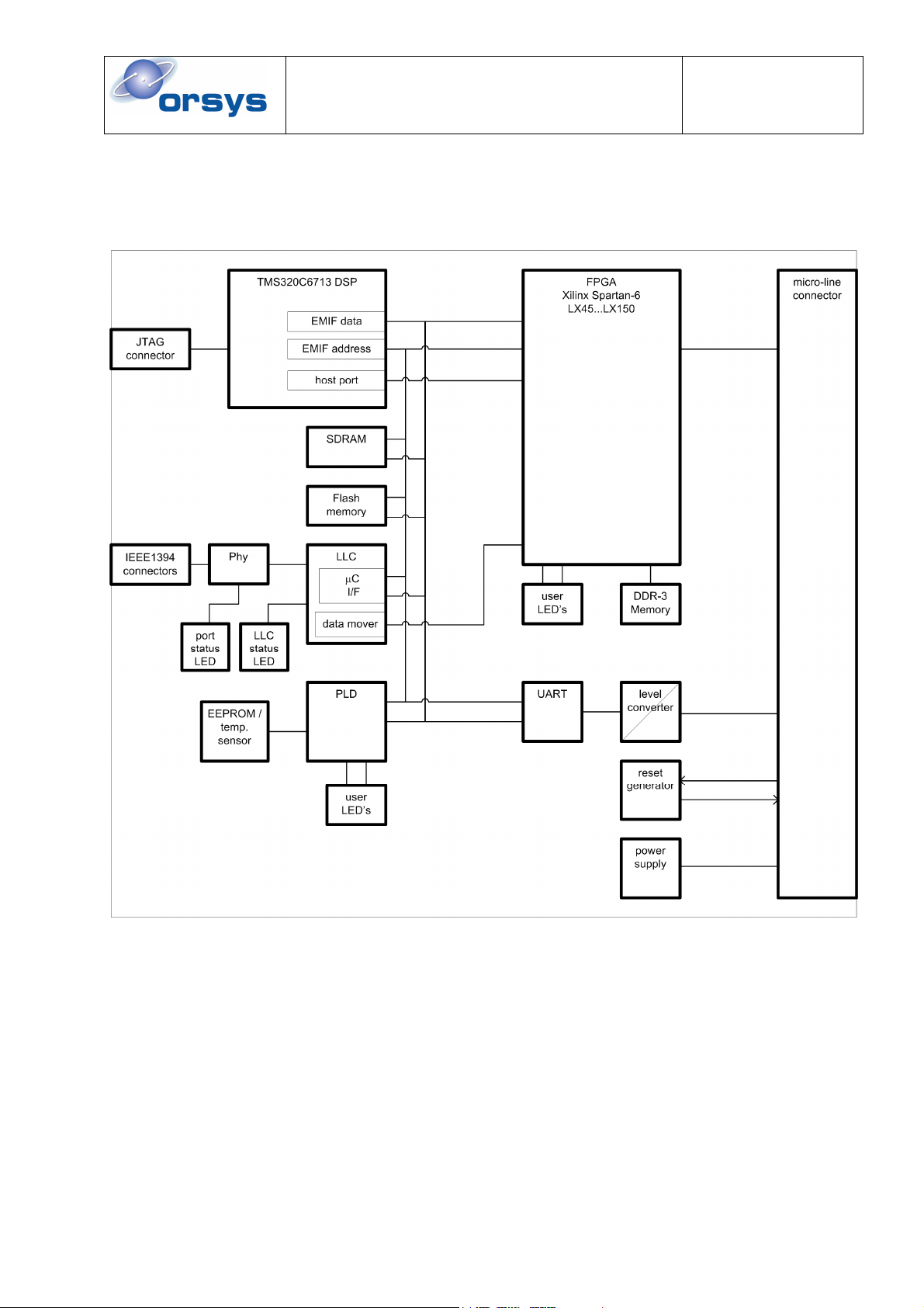
2.1 Block Diagram of the C6713Compact-2
Figure 1: Block diagram of the C6713Compact-2

HARDWARE REFERENCE GUIDE
MICRO-LINE®C6713Compact-2
Date : 11 April 2012
Doc. no. : C6713Cpt-2_hrg
Iss./Rev : 1.0
Page : 9
JTAG
emulator
connector
red LED (FPGA)
micro-line connectors
green LED (FPGA)
red LED (PLD)
green LED (PLD)
DSP SDRAM IEEE1394
physical layer transceiver (Phy)
Flas
h
memory
FPGA DDR
3
memory
IEEE1394
port active LED (yellow)
LLC status LED
IEEE1394
connectors
UART
Figure 2: Component side of the C6713Compact-2
EEPROM / temperature sensor IEEE1394 link layer controller (LLC)
SDRA
M
PLDmicro-line connector
s
Figure 3: Bottom side of the C6713Compact-2
2.2 Connectors
2.2.1 micro-line®Connector
The micro-line®connector is the main connector of the C6713Compact-2. It provides access to all
signals that are needed during operation. The signals on the micro-line®connector can be grouped
into the following categories:
•power supply
•DSP and board interfaces
•FPGA specific signals (their function depends on the respective FPGA design)

HARDWARE REFERENCE GUIDE
MICRO-LINE®C6713Compact-2
Date : 11 April 2012
Doc. no. : C6713Cpt-2_hrg
Iss./Rev : 1.0
Page : 10
Historically the micro-line®connector carried two groups of signals:
•power supply
•the micro-line®peripheral interface which allows a straightforward access to peripherals
•Processor and board specific interfaces, such as timers and serial ports
Nowadays, with the FPGA technology of the C6713Compact-2, most of the micro-line®signals can
be freely used for nearly any interface by using an appropriate FPGA design. However, the micro-
line®peripheral interface is still available. It now consists of an FPGA design, which is available as
a separate board support package.
The pinning of the micro-line®connectors is described in chapter 7.
2.2.2 JTAG Connector
The JTAG connector is used during application development. It contains the JTAG interface of the
DSP and the FPGA.
For the DSP, the JTAG interface is used for debugging and loading applications to the DSP.
However, for permanent storage of an application, the RS-232 interface in conjunction with the
Flash File System is used.
The DSP JTAG interface is used together with an emulator (from Texas Instruments or other
vendors) and Code Composer Studio (from Texas Instruments).
For the FPGA, the JTAG interface can be used to quickly load and test FPGA designs during the
development phase of a project and for debugging FPGA designs using Xilinx chipscope.
However, in end application environment, the FPGA is usually loaded by DSP software in one of
two ways:
•By application software during runtime. In this case the FPGA code must be linked to the
application code. This is useful e.g. for test software that must use a specific FPGA version.
•By the Flash File System during system startup. The FPGA code must have been stored to
Flash memory previously using the Flash File System utilities. Please refer to the Flash File
System User's Guide, which comes as a separate document. This method is typically used
for system deployment.
In order to connect the standard DSP emulators and FPGA download cables, an adapter is
delivered with the C6713Compact-2. This adapter is described in chapter 7.4.
2.2.3 IEEE1394 Connectors
The C6713Compact-2 has two IEEE1394 connectors. They can be used with the standard 6-pin
cables. The C6713Compact-2 can be factory configured for using alternative IEEE1394 connectors
for situations where the cable connectors can't be used (e.g. routing IEEE1394 to a carrier board).
2.3 Interfaces and Hardware Components
2.3.1 FPGA
The FPGA on the C6713Compact-2 can be used for a predefined application using one of the
board support packages provided by ORSYS, or it can be programmed by the user to any
customized design by using the FPGA development package. Using FPGA technology allows
flexible interfacing to nearly any hardware over the micro-line®connector. The user is no longer
restricted to a fixed pinning of the micro-line connector. Instead, the required signals can be routed
to nearly any pin on the micro-line®connector. Programmable interface standards allow a wide
range of interface standards, such as LVTTL or LVDS.
HARDWARE REFERENCE GUIDE
MICRO-LINE®C6713Compact-2
Date : 11 April 2012
Doc. no. : C6713Cpt-2_hrg
Iss./Rev : 1.0
Page : 11
The FPGA has access to the following signal groups:
•DSP EMIF (data bus, address bus, control signals)
•signals of the micro-line®connector
•DDR3 memory
•data mover port of the IEEE 1394 Link Layer Controller
•DSP peripherals (such as HPI, McASP, GPIO)
•JTAG interface
•DSP interrupts
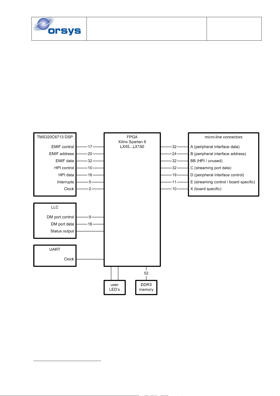
The figure below gives an overview, how the FPGA is connected on the C6713Compact-2. The
description of the micro-line®connectors in parentheses show the classic functions, as they are
implemented by previous micro-line® CPU and peripheral modules. The user is not restricted to this
scheme. Instead, the signals may be routed freely by custom FPGA designs.
Figure 4: FPGA connections overview1
After power up or a hardware reset, the FPGA is cleared. The FPGA can then be loaded over
JTAG, by application software or by the Flash File System. Details on FPGA loading can be found
in the application examples that are delivered together with the C6713Compact-2. The FPGA can
be loaded at any time and it is also possible to load it again at some later time with a different
design. For a detailed description of the signals available at the FPGA, please refer to the FPGA
development documentation. A complete list of available signals is included in the FPGA
development kit documentation and as a user constraints (UCF) file.
1The DDR3 memory is only available with LX75…LX150 FPGA devices.

HARDWARE REFERENCE GUIDE
MICRO-LINE®C6713Compact-2
Date : 11 April 2012
Doc. no. : C6713Cpt-2_hrg
Iss./Rev : 1.0
Page : 12
2.3.2 IEEE1394 Interface
The C6713Compact-2 uses the Texas Instruments TSB12LV32 general purpose link layer
controller (LLC) and a TSB41AB2 physical layer transceiver (Phy). This chipset provides
•400Mbit/s communication according to IEEE1394a
•32,768,000 bytes/s continuous isochronous data transfer
•two independent data paths: the micro-controller interface and the data mover port
•two 1394 ports to build up networks without the need for repeaters or hubs
Figure 5: Block diagram of the IEEE1394 interface
For IEEE1394 operation, transaction layer software runs on the DSP and accesses the LLC over
the micro-controller interface. The transaction layer allows incoming and outgoing asynchronous
transactions with up to 2048 bytes per packet.
The LLC can generate interrupts which are routed through the PLD. Please see chapter 3.10 and
2.5.8 for details.
Isochronous data streaming is usually routed to the datamover port of the LLC. The datamover port
can only be accessed by the FPGA. From the FPGA, the data stream can be routed to either the
DSP, or to the micro-line®bus, using a board support package or a customized FPGA design. The
FPGA can receive or control the cycle clock for isochronous transfers and it has access to the LLC
status line STAT1.
2.3.2.1 IEEE1394 Power Supply
Between the LLC and the Phy, there is isolation barrier, which is implemented using Texas
Instrument's bus-holder isolation. Therefore, the Phy must be supplied by a separate voltage. This
can be done locally over the micro-line®connector pins P6 and P7 (e.g. using an appropriate
PowerSupply board), or remote over the IEEE1394 cable.
Further, the C6713Compact-2 can be hardware-configured to supply voltage to the IEEE1394
cable. Please refer to chapter 8.2 for details.
2.3.3 External Memory (on-board SDRAM)
The C6713Compact-2 uses 32-bit wide SDRAM with 64MByte. This provides a large space for
storage of data as required e.g. for image processing. The memory access timings are based on
the EMIF clock which is set up to 90MHz or 100MHz by the Flash File System, depending on the
board version.
Compared to the internal memory of the DSP, the external memory is slower and it must share the
same EMIF with other peripherals, such as the UART. Therefore it is strongly recommended to use
the DSP's cache where possible. Further, time critical code and or data can be placed in internal
memory for fast access.

HARDWARE REFERENCE GUIDE
MICRO-LINE®C6713Compact-2
Date : 11 April 2012
Doc. no. : C6713Cpt-2_hrg
Iss./Rev : 1.0
Page : 13
2.3.4 Flash Memory
The C6713Compact-2 uses an S29GL064 (8Mbyte) or an S29GL256 (32Mbyte) flash memory for
non-volatile storage. The flash memory is 16 bit wide and can hold up to 32Mbytes of data. It is
used for permanent storage of application code.
After reset or power up, the DSP boots from the first address in flash memory. The DSP internal
boot loader copies the first 1K byte to internal memory at address 0 and executes it. Further
loading requires a secondary loader program.
On the C6713Compact-2, the flash memory is managed by the Flash File System. The Flash File
System is booted after reset or power up. It first looks for commands from a host on the RS-232
interface (See chapter 5for a description of the host side utilities) and then loads the user program
that is selected for auto-boot. Future versions of the Flash File System may have a more complex
startup process, including loading FPGA code. Please refer to the separate documentation, if
available.
2.3.5 DDR3 memory
The C6713Compact-2 has 256 MB of DDR3 memory which is directly connected to one of the
FPGA's memory controller blocks (MCBs). To use this memory, an appropriate FPGA design is
required. Actual access speed of the DDR3 memory is defined by the respective FPGA design, but
is limited to 400MHz which corresponds to DDR3-800. Bus width of the DDR3 memory is 16 bits.
The DDR3 memory is only available on boards with an LX75 FPGA or higher.
2.3.6 PLD
The PLD contains the glue logic of the board. It provides all necessary signals to access the board
hardware. It also contains some register that configure board operation. See chapter 3.10 for a
description of the PLD registers,
2.3.7 UART / RS-232 Interface
The RS-232 interface is realized by the UART device TL16C550 from Texas Instruments which is
connected to a RS-232 line driver. The RS-232 interface can be used as general purpose
communication interface. Functions like printf(), getch(), putch() etc. are executable by the
application program on the micro-line®C6713Compact-2, using the RS-232 interface as a
communication channel, e.g. to transfer measurement results to a host system or to control a
connected peripheral device. Another common usage of the RS232 interface is to output
debugging information during testing.
The interface consists of the signals TxD (transmit data), RxD (receive data), RTS (request to
send) and CTS (clear to send). These signals are available at the micro-line®connector. Please
refer to chapter 7.1 for details. The CTS signal can be configured as additional reset input of the
board.
The UART TL16C550 can operate at data rates of up to 230400 baud at even multiples of 115200
baud or up to 691200 baud at odd multiples[17].
The UART can generate various interrupts which are routed over the PLD. Please see chapter
3.10 and 2.5.8 for details.
The RS-232 line driver can be switched into shutdown mode to reduce power consumption. Please
see chapter 3.10.5 for details.
2.3.8 Serial EEPROM
The C6713Compact-2 board provides a 256 byte EEPROM storage which is integrated into the
board's temperature sensor. In this EEPROM the device serial number or other application specific
parameters can be stored. Software drivers for the EEPROM are shipped together with the
C6713Compact-2. Further information can be found in [18].
The EEPROM is connect to the PLD by a separate I2C interface. It does not use the I2C interfaces
of the DSP. The EEPROM can be accessed by the I2C bus control register (see chapter 3.10.7).
HARDWARE REFERENCE GUIDE
MICRO-LINE®C6713Compact-2
Date : 11 April 2012
Doc. no. : C6713Cpt-2_hrg
Iss./Rev : 1.0
Page : 14
2.3.9 Temperature Sensor
The C6713Compact-2 board provides a temperature sensor with a serial I2C-Bus interface in order
to determine the board temperature during operation. The sensor can measure a temperature
range from –55 degrees Celsius up to +125 degrees Celsius with a resolution of 0.03125 degree. If
the C6713Compact-2 is operated in an environment where it is exposed to high temperatures, the
temperature sensor can be used to detect over-temperature conditions. The CPU-internal
temperature is roughly 15 degrees Celsius above the temperature measured by the sensor.
Software drivers for the temperature sensor are shipped together with the C6713Compact-2.
Further information can be found in [18].
The temperature sensor is connected to the PLD by a separate I2C interface. It does not use the
I2C interfaces of the DSP. The temperature sensor can be accessed by the I2C bus control register
(see chapter 3.10.7)
2.3.10 Reset Generator and Watchdog
The C67123Compact CPU board provides a triple voltage supervising reset generator which
generates a defined reset pulse in case of one or more of the following events:
•power up
•software reset (via the module control register; see chapter 3.10)
•the /RESETIN pin is active (low)
•one of the supply voltages drops below a certain limit
•the reset generator's watchdog timer is enabled and has expired
•The reset function of the CTS line is activated and CTS is active.
During the reset pulse the micro-line®signals /RESETOUT and RESETOUT are activated.
The reset generator circuit has a watchdog timer, that causes a reset if it is not reset periodically by
software. The watchdog timer is disabled by default, thus no resets will be generated and the
watchdog timer does not need to be reset by software.
Enabling the watchdog timer is described in chapter 3.10.9; resetting the watchdog timer is
described in chapter 3.10.6.
2.3.11 External Flags (XF signals)
The C6713Compact-2 provides two dedicated general-purpose pins that can be configured as
either inputs or outputs. When configured as an output, the user can write to a PLD register to
control the state driven on the output pin. When configured as an input, the user can detect the
state of the input by reading the state of a PLD register. Please refer to chapter 3.10 for a
description on how to control the XF pins.
2.3.12 Power Supply of the Board
Nominal supply voltage for the C6713Compact-2 is 5 V. If 3.3 V supply is required, please contact
Orsys.
For operation of the IEEE1394 interface, an additional supply voltage of 8…30 V is required which
can be provided over the IEEE1394 cable or locally.
Please refer to the chapters 8.1, 8.4 and 8.5 for further details.
CAUTION:
The C6713Compact-2 is not protected against reversed voltage. Please be careful when
connecting the power supply to the board. Applying reversed voltage will damage the board !

HARDWARE REFERENCE GUIDE
MICRO-LINE®C6713Compact-2
Date : 11 April 2012
Doc. no. : C6713Cpt-2_hrg
Iss./Rev : 1.0
Page : 15
The following voltages are generated internally on the C6713Compact-2:
•1.4 V supply voltage for the processor core
•3.3 V supply for the board-internal logic and I/O
•1.25 V supply voltage for the FPGA core
•1.5 V for the DDR3 memory
2.4 Status LED's
On the C6713Compact-2 are three groups of LED's:
•user programmable LED's controlled by the PLD
•user programmable LED's controlled by the FPGA
•IEEE1394 status LED's
2.4.1 User Programmable LED's (PLD)
These LED's are controlled by PLD registers (see chapter 3.10). They can be used by application
software to display certain events or states. For example, the red LED could be used to indicate
error conditions. Both LED's can be switched on and off by setting the respective bits in the module
control register. Further, the red LED can also be controlled by some hardware sources:
•DSP access to the CE1 address space
•DSP is halted by the ARDY input
•DSP interrupt EXT_INT6 pending
•DSP interrupt EXT_INT7 pending
These hardware sources can be configured by the LED source register. Whenever one of the
selected conditions is true, the LED will light.
Examples for software controlled usage of the LED's are:
•displaying an error condition by the red LED
•check of board activity by toggling one of the LED each time the main loop is executed
•CPU load indicator: enabling the LED during interrupt handlers or calculations
2.4.2 User Programmable LED's (FPGA)
The FPGA can control a red and a green LED. Their function is defined by the respective FPGA
design or board support package and is not documented here.
2.4.3 IEEE1394 Status LED's
Two LED's provide status information of the IEEE1394 interface:
•a yellow LED the shows if there is an active 1394 connection
•a green LED which shows the LLC status
The yellow LED will light whenever
•the Phy is supplied with power (from cable or local supply) and
•there is an active connection to another 1394 device
The green LED is connected to the LLC's STAT 2 line. This LED will light whenever the STAT2 line
of the LLC is low. By default, this happens whenever there is data in the LLC's receive FIFO
waiting to be processed. The STAT2 line can also be configured to display other conditions. Please
refer to [19] for details.
2.5 DSP peripherals
The DSP of the C6713Compact-2 board has a number peripheral interfaces integrated on the chip.
These interfaces are described briefly in this chapter. Hardware and programming details can be
found in the respective literature from Texas Instruments [5] .. [8].

HARDWARE REFERENCE GUIDE
MICRO-LINE®C6713Compact-2
Date : 11 April 2012
Doc. no. : C6713Cpt-2_hrg
Iss./Rev : 1.0
Page : 16
Some of the DSP peripherals share pins with other peripherals. Therefore, care must be taken
when using multiple peripherals, to ensure that all signals are really available.
2.5.1 Multichannel Audio Serial Ports (McASP)
The McASP is a serial port optimized for the needs of multi-channel audio applications. Two
McASP ports are implemented on the TMS320C6713. The McASP interface is described in [3] and
[6].
The signals of the McASP interfaces are shared with signals of other DSP peripherals:
•McBSP 0
•McBSP 1
•Timer 1
•GPIO 5 / EXT_INT5
•GPIO 4 / EXT_INT4
•HPI.
Chapter 7.2 contains a detailed listing of the shared signals that are available at the micro-line®
connector. By default, the McASP functions of shared signals are disabled. Further information can
be found in [3].
On the C6713Compact-2, McASP0 is available at the micro-line®connector, except for the signal
AMUTEIN0, which is connected to the FPGA.
McASP1 is completely connected to the FPGA. Therefore usage of McASP1 requires an
appropriate BSP or a custom FPGA design. Further, McASP 1 is only available if the host port
function is disabled. See chapter 8.2 for details on host port configuration. Please refer to chapter
7.2 for the connector pin assignment.
2.5.2 External Memory Interface (EMIF)
The EMIF is the main interface for external peripherals. It is connected to
•the external memory (on-board SDRAM, flash memory)
•the on-board peripherals (UART, LLC, PLD)
The EMIF can be used to access external hardware by using an appropriate FPGA design. This
can be either a board support package from ORSYS, or a custom FPGA design.
The EMIF is mapped into the DSP's address space, separated into four categories, or CE spaces:
•CE0 which is used for external RAM (on-board SDRAM)
•CE1 which is used for flash memory and the on-board peripherals of the C6713Compact-2
•CE2 and CE3 which can be used by the FPGA
Please refer to chapter 3for a detailed description of the CE space usage and their address
ranges.
2.5.3 Inter Integrated Circuit (I2C) Interfaces
The TMS320C6713 DSP has two I2C interfaces. These interfaces can be used for accessing
peripherals, like temperature sensors, EEPROMS, A/D and D/A converters, etc.. The I2C interfaces
are described in [3] and [8].
On the TMS320C6713 DSP, the signals of I2C interface 1 are shared with signals of the McBSP
interface 1. Chapter 7.2 and Table 18 show the shared signals. Further information can be found in
chapter 7.6.5 and in [3].
On the C6713Compact-2, only I2C interface 1 is available. The I2C interface 0 is not connected.
The I2C function of shared signals is disabled by default.

HARDWARE REFERENCE GUIDE
MICRO-LINE®C6713Compact-2
Date : 11 April 2012
Doc. no. : C6713Cpt-2_hrg
Iss./Rev : 1.0
Page : 17
2.5.4 General Purpose Input / Output Peripheral (GPIO)
On the C6713Compact-2 board, usage of the GPIO peripheral is not recommended, since there
are no direct connections to the micro-line®connector. Instead, the following signals can be used
for GPIO:
•the external flags (XF0, XF1)
•the McBSP signals (see [5], chapter "McBSP Pins as General-Purpose I/O")
•free FPGA pins (requires a BSP or custom FPGA design)
The GPIO signals of the DSP must be kept in their default configuration to prevent signal
contention.
2.5.5 Multi-channel Buffered Serial Ports (McBSP)
The TMS320C6713 DSP provides two independent multi-channel buffered serial ports. Each port
can communicate a full duplex, continuous data stream at rates up to 75 Mbps. These ports can be
used for inter-processor communication as well as for connecting industry standard peripheral
devices like codecs, A/D or D/A devices.
An implemented multi-channel protocol which provides up to 128 channels opens a variety of
applications such as T1/E1 framers, MVIP framers etc.
The multi-channel buffered serial port is similar to the standard synchronous serial interface of the
Texas Instruments TMS320C2000, ’C3x or ’C5000 DSP families and can be programmed to be
compatible with almost any other synchronous serial interface. It consists of the signals DRx (data
receive), DXx (data transmit), CLKRx (clock receive), CLKXx (clock transmit), FSRx (frame sync
receive) and FSXx (frame sync transmit). Additionally the TMS320C6211/6711/6712 processors
support an external McBSP CLKSx (clock source) signal. The 'x' in the signal name stands for the
channel number and is 0 or 1 for McBSP channel 0 and 1 respectively.
The above mentioned signals can also be used as software controllable digital general purpose
inputs or outputs.
Possible general purpose inputs are: DRx, CLKRx, CLKXx, FSRx, FSXx and CLKSx.
Possible general purpose outputs are: DXx, CLKRx, CLKXx, FSRx and FSXx.
On the TMS320C6713 DSP, the McBSP peripherals share signals with
•McASP 0
•I
2C 1
On the C6713Compact-2 board, the McBSP signals are directly routed to the micro-line®
connector. Chapter 7.2 contains a detailed listing of the connector pin assignments as well as a list
of the shared signals in Table 16. The McBSP function of shared signals is enabled by default.
Information on configuring and using the McBSP interface can be found in [3] and [5]. Further
information can be found in chapter 7.6.5.
2.5.6 Timers
The TMS320C6713 DSP provides two independent 32-bit general purpose timers. The timers
support two signaling modes and can be clocked by an internal or an external source. Each timer
has an input pin and an output pin. With an internal clock, for example, the timer can trigger an
external A/D converter to start a conversion, or it can trigger the DMA controller to start a data
transfer. If connected to an external digital signal source, the timer can count external events and
interrupt the DSP after a specified number of events.
Each timer input pin TINP0 / TINP1 can either function as timer clock input or be configured for
general purpose digital input. Each timer output pin TOUT0 / TOUT1 can either function as clock
output or be configured for general purpose digital output.
On the TMS320C6713 DSP, the timer signals are shared with the McASP 0 peripheral.
HARDWARE REFERENCE GUIDE
MICRO-LINE®C6713Compact-2
Date : 11 April 2012
Doc. no. : C6713Cpt-2_hrg
Iss./Rev : 1.0
Page : 18
On the C6713Compact-2 board, the timer signals are directly routed to the micro-line®connector.
Chapter 7.2 contains a detailed listing of the connector pin assignments as well as a list of the
shared signals. The timer function of shared signals is enabled by default. Information on
configuring and using the timers can be found in [3] and [5].
2.5.7 Host Port Interface (HPI)
The TMS320C6713 DSP provides a 16 bit wide host port interface (HPI) which can be used by a
host processor to directly access the memory of the DSP. Here, the host device accesses the HPI
as a master and the DSP acts as a slave. The host processor and the DSP can exchange
information via DSP-internal and on-board memory. The host also has direct access to memory-
mapped peripheral registers. Connectivity to the DSP memory space is automatically provided
through a DMA mechanism. The host device controls the HPI transfers via dedicated HPI address
and data registers which are not accessible for the DSP. Here, the DMA auxiliary channel connects
the HPI to the DSP memory space.
On the TMS320C6713 DSP, the HPI peripherals shares signals with
•McASP 1
•GPIO
Further information about the HPI can be found in [3] and [5].
On the C6713Compact-2 board, the host port is only available with an appropriate FPGA design,
thus by using either an appropriate board support package from ORSYS, or a custom FPGA
design. The HPI function of shared signals is enabled by default (by both, the DSP, and default
hardware configuration of the C6713Compact-2 (see chapter 8.2).
2.5.8 Interrupts
Four maskable and one non-maskable interrupt inputs allow on-board and external hardware
devices to interrupt a running program and jump into a dedicated interrupt service routine. DMA
transfers can also be triggered by interrupts. Interrupt line status can be polled by software.
Detailed information about interrupts can be found in [3], [5] and [4].
On the TMS320C6713 DSP, the interrupt lines are shared with GPIO signals and the McASP
ports.
On the C6713Compact-2 board, two interrupts (EXT_INT6, EXT_INT7) are handled by the PLD
and two (EXT_INT4 and EXT_INT5) are handled by the FPGA. Possible PLD interrupt sources
are:
source DSP interrupt line
LLC interrupt EXT_INT6
LLC STAT0 line
UART interrupts
flash memory ready condition
FPGA I/O power fail condition
EXT_INT7
FPGA EXT_INT6, EXT_INT7
Table 1: PLD interrupt sources of the C6713Compact-2
Detailed information about interrupt handling by the PLD can be found in chapter 3.10.

HARDWARE REFERENCE GUIDE
MICRO-LINE®C6713Compact-2
Date : 11 April 2012
Doc. no. : C6713Cpt-2_hrg
Iss./Rev : 1.0
Page : 19
Figure 6: C6713Compact-2 interrupt routing
Using the interrupt lines with the alternative GPIO function is not recommended except for polling
the state of an interrupt line. For other GPIO purposes, the XF signals or the McBSP signals
should be used.
If the McASP function of the interrupt signals must be used, an appropriate FPGA design is
required, which
•must route the McASP signals to the micro-line®connector or an FPGA-internal source
•must not route any interrupt sources to these signals
Programming note: For proper operation of the on-board interrupt sources the interrupt
configuration of the TMS320C6713 DSP must be kept at its default values. Therefore the following
registers of the DSP must not be programmed: Interrupt multiplexer (MUXH / MUXL) and external
interrupt polarity (EXTPOL).
2.5.9 DMA
The TMS320C6713 DSP provides an enhanced DMA (EDMA) controller with 16 channels and 16
possible synchronization events. It can be used to transfer data between two locations anywhere in
the address range of the C6713Compact-2. EDMA transfers can be triggered by software, internal
events, such as timers or the serial port, or by external events from connected peripherals.
External events are signaled by means of the interrupt lines. DMA operations can be chained, that
means the end of one transfer starts the next transfer. This provides a powerful, flexible way to
perform continuous operation without CPU intervention as well as scatter-gather transfers. The
enhanced DMA can perform element transfers with single cycle throughput in the case that the
source and destination are on two different internal buses and each provides a single cycle
throughput. In this case a maximum data throughput of 300 MWords per second can be achieved.
Furthermore, there is another, more simplified DMA register set available: the QDMA (quick DMA).
QDMA transfers can be set up within five CPU clock cycles register accesses and can be re-
started with one a single register access.
On the TMS320C6713 DSP the DMA is the only way to perform fast block transfers from or to non-
cached locations.
Further information can be found in [3], [5], [11] and [12].

HARDWARE REFERENCE GUIDE
MICRO-LINE®C6713Compact-2
Date : 11 April 2012
Doc. no. : C6713Cpt-2_hrg
Iss./Rev : 1.0
Page : 20
3 Memory Maps and Description of the Registers
3.1 TMS320C6713 Memory Map
The memory map of the TMS320C6713 is divided into several sections:
•internal memory
•DSP peripherals
•EMIF CE spaces CE0 .. CE3
The external devices are located at different CE (Chip Enable) spaces. The timing of each CE
space can be individually set up. The complete memory map is shown in Table 2. For a more
detailed memory map of the DSP please refer to [3].
address range (hex) size (bytes) description
0000 0000 - 0002 FFFF 192K Internal RAM
0003 0000 - 0003 FFFF 64K Internal RAM/Cache
0004 0000 - 017F FFFF 24M - 256K Reserved
0180 0000 -3C1F FFFF 938M flash memory & DSP peripherals
3C20 0000 - 7FFF FFFF 1G + 62M Reserved
8000 0000 - 8FFF FFFF 256M (usable: 128M ) EMIF CE0
9000 0000 - 9FFF FFFF 256M (usable: 128M ) EMIF CE1
A000 0000 - AFFF FFFF 256M (usable: 128M ) EMIF CE2
B000 0000 - BFFF FFFF 256M (usable: 128M ) EMIF CE3
C000 0000 – FFFF FFFF 1G Reserved
Table 2: Memory map of the TMS320C6713 DSP
Table of contents


