ORTAL Wilderness 60H Series User manual

Ortal Installation Manual: Wilderness 60H Series (V1.0)
Installation and Operation Manual
Wilderness 60H Series
Wilderness 60H Series Fireplaces:
Wilderness 60H Front Facing
Wilderness 60H Corner (RS/LS)
Wilderness 60H Three Sided

2
General
Safety Information and Warnings
IMPORTANT NOTE: LOCAL CODE
Local codes and regulations that are more stringent than the requirements in this manual take precedence over Ortal requirements.
WARNING: REVIEW ALL WARNINGS
Be sure to review all safety warnings and installation guidelines contained in this manual. Consider installation location, vent
configuration, clearances, structural requirements, framing and finish materials, and local codes. ALL warnings and instructions apply
to all products manufactured and distributed by Ortal.
WARNING: DO NOT OPERATE FIREPLACE IF:
The glass is NOT properly secured in place; Connection points are not sealed (for fireplaces with glass-to-glass connections);
Glass is cracked; You smell gas; Any part of the fireplace has been under water; You have any doubt about safe operation of the
fireplace; Or if any part has been under water, do not use the fireplace. Immediately call a qualified, professional service technician
to inspect the fireplace and to replace any parts of the control system and any gas controls which have been under water.
WARNING: ELECTRICAL GROUNDING
All electrical connections must be properly installed, insulated, and secured to avoid potential ELECTRICAL SHOCK and FIRE
HAZARD and malfunction of the system. Consult local building code requirements. In the absence of local codes, refer to the National
Electric Code, ANSI/NFPA 70, or the Canadian Electric Code, CSA C22.1.
WARNING: MATERIAL USAGE
All materials and objects used to carry out the installation must be certified/approved or specified by Ortal and are suitable for use.
Do NOT install the system with different materials or objects than those approved for installation by Ortal.
WARNING: INSTALLATION AND SERVICE
Installation and repairs on the fireplace and vent system must be done by an authorized Ortal qualified installer service agency or
gas supplier. If these components are not installed by an authorized Ortal dealer/installer, the warranty of all components will be void
and Ortal will not be responsible for any damage caused by improper installation. The fireplace should be inspected before use and
at least annually by a professional service person. More frequent cleaning may be required due to excessive lint from carpeting,
bedding material, etc. Control compartments, burners and circulating air passageways of the fireplace must be kept clean. Any
alteration to the product can cause soot or carbon to form and may result in damage. This damage and any other damage that results
from not following the instructions outlined in this manual is not the responsibility of Ortal.
WARNING: HEAT BARRIER
A barrier designed to reduce the risk of burns from hot viewing glass is provided with this fireplace and shall be installed. The fireplace
MUST not be used without the heat barrier in place. If the barrier becomes damaged, the barrier shall be replaced with the
manufacturer’s barrier for this fireplace. Any safety screen, guard, or barrier removed for servicing the fireplace must be
replaced before operating.
WARNING: FIREPLACE TEMPERATURE
Due to hot temperatures, the fireplace should be located out of traffic and away from furniture and draperies.
Children and adults should be alerted to the hazards of high surface temperature and should stay away to avoid burns or clothing
ignition. Clothing or other flammable material should not be placed on or near the fireplace. Young children should be carefully
supervised when they are in the same room as the fireplace. Toddlers, young children, and others may be susceptible to
accidental contact burns. A physical barrier is recommended if there are at-risk individuals in the house. To restrict access to a
fireplace or stove, install an adjustable safety gate to keep toddlers, young children, and other at-risk individuals out of the room and
away from hot surfaces.
WARNING: GLASS HANDLING
Only an Ortal certified installer is authorized to remove the glass using an 8-inch glass-handling suction cup.
WARNING: INSTALLATION AND OPERATION
The fireplace and accompanying components must be installed as an OEM installation in manufactured homes (USA only) or an
aftermarket permanently located, or a mobile home, where not prohibited by local codes. The fireplace must be installed in
accordance with the Manufacturer's instructions and the Manufactured Home Construction and Safety Standard, Title 24 CFR, Part
3280, in the United States, or the Standard for Installation in Mobile Homes, CAN/CSA Z240 MH Series, in Canada. Exceeding the
restrictions imposed in these instructions may result in a fire or explosion, causing property damage, personal injury, or
loss of life. Ortal will not be responsible for any damage caused by improper installation. Do not store or use gasoline or
other flammable vapors and liquids near this fireplace.
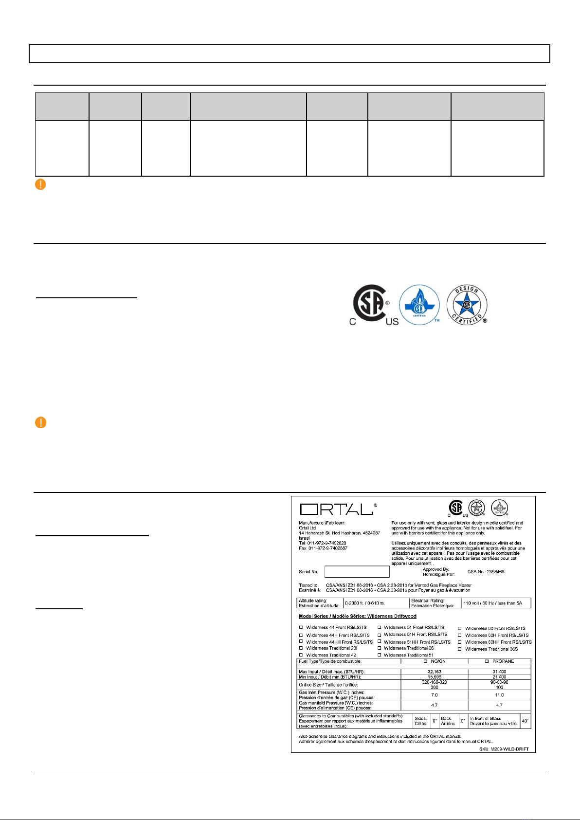
WARNING: GAS FIREPLACE
This fireplace is for use only with the type of gas indicated on the rating plate. These fireplaces are not convertible for use with other
gases unless a certified kit is used, and the conversion is performed by an authorized and qualified technician. Applicable standards
are Vented Gas Fireplace Heaters ANSI Z21.88 / CSA 2.33a and Gas-fired Fireplaces for Use at High Altitudes CAN/CGA 2.17-M91

3
Table of Contents
General 2
Safety Information and Warnings 2
Product Information 5
Models 5
Certification 5
Rating Label 5
Zero-Clearance Stand-Offs 6
Installation 7
Prior to Installation 7
Locate the Fireplace 7
Fireplace Installation 7
First Trip to Site: Planning 7
Second Trip to Site: Installation 7
Third Trip to Site: Startup 8
Post-Installation 8
Initial Burning Period 8
Final Inspection Procedure 8
Final Checks and User Instruction 8
Building Around the Fireplace 9
Building Checklist 9
Framing 10
Framing Requirements 10
5/8” Type X Drywall Requirements 10
Chase Floor/Platform 10
Framing Dimensions 11
General Clearances 14
Heat Release 15
Air Intake 17
Mounting a TV/Artwork 19
Access Panel 21
Chase Area Minimum 21
Recessed Ledge Detail 22
Structural Weight Support 23
Step-by-Step Chase Construction 24
Finishing 25
Flush Installation
25
Recessed Installation 26
Venting 27
General Venting Requirements 27
Vent Configurations 27
Vent Restrictor Sizing Guidelines 29
Clearances 30
Horizontal Termination Clearance Diagram 31
Vertical Termination Clearance Diagram 33
Chimney Shroud 34
Installation 34
Maintenance 35
Gas 35
Gas Pressures 35
Gas Conversion 35
High Altitude Requirements 35
Routing the Gas Line 36
Gas and Electrical Components 37
Electrical 39
Electrical Requirements 39
Pairing the Remote and Receiver 39
Wiring Diagrams 40
Carbon Monoxide Detector Wiring Diagrams 44
Home Automation Wiring Diagram 46

4
Driftwood Firelog Set 47
Firelog Installation Warnings 48
Driftwood Firelog Setup 49
Firelog Base/Tube Position Adjustment 52
Adjustment Instructions 53
Operation 57
10-Button Remote Control Handset 57
Operating Instructions 57
Puck Handset 58
Operating Instructions 59
Wall Switch 60
Operating Instructions 60
MyFire App 61
Operating Instructions 61
MyFire Wi-Fi Box 61
Fireplace Maintenance 62
General Maintenance 62
---

5
Product Information
Models
Series Models Burner Certification Standard Available
Gas Types Venting Power Venting
(Optional Accessory)
Wilderness
60H
60H Front
60H RS
60H RS
60H TS
Driftwood
Firelog
Set
US: ANSI Z21.88 - 2016
Canada: CSA 2.33 - 2016
Natural Gas
or
Propane
Type: Direct Vent
Size: 5”x8”
(co-axial)
Type: Direct Vent
Size: 3”x5” (co-axial)
NOTES:
For more information on Power Venting, please refer to the Power Vent System Installation and Operation Manual.
Venting is not supplied by Ortal with the fireplace. The fireplace is certified to be used with, and can be obtained from, the
vent manufacturers outlined in “General Venting Requirements” section.
Certification
Wilderness 60H series fireplaces have been tested and approved by CSA Group for safety and efficiency for use with Natural Gas
(NG) and Propane (LP) only, and NOT for use with solid fuels.
CSA Group is approved by the American National Standards Institute (ANSI) as an Accredited Standards Developer.
Certification Standard:
US: ANSI Z21.88 – 2016: Vented Gas Fireplace Heaters
Canada: CSA 2.33 – 2016: Vented Gas Fireplace Heaters
Products:
CLASS 2901 84: DOMESTIC HEATERS (GAS) Vented Fireplace: Certified to US Standard
CLASS 2901 04: DOMESTIC HEATERS (GAS) Vented Fireplace
The fireplaces are permitted for indoor use only. “Indoor” is defined as a conditioned space. The fireplaces are not approved for
outdoor or partial outdoor installation. The fireplaces must be installed while maintaining required clearances. Installation is
recommended in living spaces such as bedrooms, living rooms, great rooms, etc. The fireplaces are not approved for closet
installation. The fireplace must be installed according to Ortal requirements in addition to any local codes that may apply, such as
USA: ANSI Z223.1/NFPA 54, Canada: CSA B149.
IMPORTANT:
Consult the authority having jurisdiction to determine the need for a permit prior to starting the installation.
It is the responsibility of the fireplace dealer and installer to ensure that this fireplace is installed and framed in compliance
with these instructions and all applicable codes.
Before starting, take careful note of ALL the WARNINGS in this manual.
Rating Label
The fireplace rating label is found on a metal plate separate
included with the fireplace.
DEALERS/INSTALLERS:
You MUST leave the fireplace’s rating label with the fireplace
in an area easily accessible by the owner (typically near the
access panel, if available).
You must instruct the owner before handing over the
fireplace where this label can be found.
OWNERS:
Make sure the installer leaves your fireplace’s rating label in
an area that is easily accessible for you. This information is
required for servicing and receiving replacement parts.

6
Zero-Clearance Stand-Offs
The fireplace has zero-clearance stand-offs fastened to the body of the fireplace as shown in the figures below. Stand-offs must be
fully extended upon installation.
60H Front Facing
Zero-Clearance Stand-Offs (Isometric View)
Zero-Clearance Stand-Offs (Top View)
60H Corner (RS/LS)
Zero-Clearance Stand-Offs (Isometric View)
Zero-Clearance Stand-Offs (Top View)
60H Three Sided
Zero-Clearance Stand-Offs (Isometric View)
Zero-Clearance Stand-Offs (Top View)

7
Installation
Prior to Installation
Locate the Fireplace
Keep the following factors in mind when selecting a location for the fireplace:
Fireplace clearance requirements (review “General Clearances” sections).
Heat release and air intake requirements (review “Heat Release” and “Air Intake” sections).
Adequate space for servicing.
Access panel recommendations (review “Access Panel” section).
Minimum vertical vent rise, allowed horizontal lengths, and degree of offset (review “Venting” section).
Framing and finishing requirements (review “Framing” and “Finishing” sections).
Front wall installation and finishes to be completed after fireplace and vent installation (review “Step-By-Step Chase
Construction” section).
Floor or Platform requirements (review “Platform” section).
Fireplace Installation
Use the following guidelines to ensure a smooth installation. The installation sequence is divided into three phases: Planning,
Installation, and Startup.
First Trip to Site: Planning
Consult with the contractor and go over all requirements:
Chase framing requirements.
5/8” Type X Drywall (or equivalent) requirements.
Heat release requirements.
Air Intake requirements (if applicable).
Access panel size and location.
Gas and electric specs and location.
Vent configuration.
Finishing details.
NOTE: Provide the contractor with a printed copy of the “Building Checklist” and review requirements with them.
Second Trip to Site: Installation
Confirm the following items are properly located and built to specification:
Framing (with 5/8” Type X Drywall as applicable)
Platform
Gas and electric
Access panel (if applicable)
Heat release
Air intake (if applicable)
Clear a path free of any possible obstruction to carry in the fireplace.
Uncrate the fireplace and set in place.
Make sure all zero-clearance metal stand-offs on the outside of the fireplace are fully extended.
Secure the fireplace to the framing by attaching the nailing flanges to the framing. See “Securing the Fireplace” section
below.
Remove all zip ties.
Optional: Remove gas and electrical components from metal shipping plate if desired.
Move the components to the access panel location. Be mindful of the routing for future service needs.
Connect the light grounding cable to the fireplace leg closest to the access panel.
Install the vent components. See “Vent Installation” section below.
Review the front wall requirements (see “Step-By-Step Chase Construction” section) and finishing details with the contractor.
Protect the fireplace and components from damage.

8
Securing the Fireplace
The fireplace has nailing flanges attached to the face of the fireplace (see figures below). The nailing flanges are to be attached into
the framing upon installation. It is crucial to the finishing that the fireplace is stable, level, and plumb. For added stability (though not
required), re-use the shipping brackets to secure the legs of the fireplace to floor/platform.
Nailing Flanges for 60H Front Facing
Nailing Flanges for 60H Corner (RS/LS)
Nailing Flanges for 60H Three Sided
Vent Installation
Venting must be installed according to the requirements detailed in the “Venting” section of this manual in conjunction with the vent
system manufacturer’s installation instructions. Venting must be supported by the structural surrounding and not by the fireplace.
Each offset (elbow) must be strapped to reduce movement or possible disconnection.
The first section of venting must be secured to the fireplace starter collar with a minimum of 3 sheet metal screws no longer than 1/2”.
DO NOT use silicone to seal the sections. If sealing is required by the vent manufacturer or local code, use Mil-Pac sealant.
Third Trip to Site: Startup
Perform a visual inspection to confirm that all work was completed correctly and per specification.
Confirm that gas and electric are properly connected and live.
Remove the safety barrier and glass and clean the inside of the fireplace.
Install the Firelogs on the burner as specified in “Log Placement” section.
Confirm the log placement is set up per specification.
Confirm the fireplace is operating properly.
Check remote-control setup.
Remove protective layer from glass.
Clean glass.
Reinstall the glass and safety barrier.
Review operation of the fireplace and remote control with the owner.
Set up return visit to clean glass after the Initial Burning Period (see “Post-Installation” section below).
Post-Installation
Complete the following post-installation steps upon 4th trip to site.
Initial Burning Period
There is a 12-hour minimum burning period following installation of the fireplace. This 12-hour period must include a minimum of 4
consecutive hours of continuous burning. During this time, the owner or installer may notice:
The glass developing a white or “cloudy” residue.
An unusual smell
Both the residue and the smell are due to the paint on the fireplace metal heating and “burning off”. This is normal. The cloudiness
and odor will disappear after the 12-hour period elapses and the installer returns to service the fireplace and complete startup.
Final Inspection Procedure
When the 12-hour burning period is complete, the installer must return and perform the final inspection, which includes:
Cleaning the glass with a ceramic glass cleaner (otherwise the white residue will remain)
Checking the interior media setup
Checking for gas leaks
Adjusting the restrictor (if necessary)
Performing an overall check to make sure that everything is working properly.
When these activities are complete, initial startup is concluded and the fireplace may be operated by the owner.
Final Checks and User Instruction
Before releasing the fireplace to the customer for use without installer supervision, the installer must ensure that the fireplace is
burning correctly. In addition, the installer must review and explain the following to the owner:
Safety warnings
Fireplace operation
Warranty requirements
Maintenance requirements
Glass is hot during and after operation.
If any questions or concerns arise, owner must contact the local Ortal dealer/installer for support.

9
Building Around the Fireplace
Building Checklist
The following building checklist is a quick reference for a typical Ortal Wilderness 60H series fireplace
installation. This list is not exhaustive and does not supplement thorough review of the installation manual.
Fireplace Location: Ensure the location allows for min. 40” clearance from viewing area to furniture
and other combustibles. Make sure a clear path is established to allow the fireplace to be safely
transported to installation location.
Venting: Confirm vent size (5”x8”, or 3”x5” for Power Vent), vent clearance (1” on sides and bottom, 3”
on top), vent configuration, and termination location.
Height from Floor: Fireplace leg height is 9 13/16” (to bottom viewing area). Legs cannot be
removed/altered. If desired viewing area location on the wall is higher than 9 13/16”, a platform can be
built for the fireplace to stand on.
Chase Floor/Platform: Fireplace can stand on the chase floor or a platform. Floor or platform must be
able to bear the weight of the fireplace. It can be constructed out of wood, concrete, metal, or any other
solid materials (not required to be non-combustible).
Chase Construction: No materials can be attached directly to the fireplace (exception: 5/8” Type X
Drywall). The area of the chase interior must meet minimum chase area requirements (depending on
the model).
Framing: Adhere to minimum framing dimensions (or greater). The first 101/2” above the top of the
fireplace viewing area must always be non-combustible framing. For recessed fireplaces, do not exceed
12” max. front overhang depth limit. For Corner and TS models, side overhang has no limit. No material
is permitted to extend past the metal lip surrounding the fireplace viewing area.
5/8” Type X Drywall Requirements: One layer of 5/8” Type X Drywall (or equivalent) must be installed
on the exterior of the chase framing. 5/8” Type X Drywall (or equivalent) may be fastened to the top
framing stand-off only, with 1" self-tapping drywall screws 16'' on center.
TV/Artwork: TV/Art must be min. 12” above top of fireplace viewing area. First 10 1/2” min. above the
viewing area must have non-combustible framing (top front metal stand-off + non-combustible studs).
Gas Supply Line and Power Location: Locate gas line with manual shut off according to local code.
Power provided by a duplex outlet receptacle (120V, 15 amp, 60Hz) in same area as gas line.
Access Panel: Access panel highly recommended to access gas and electrical components for
servicing. Depending on the model, access panel can be placed at side or back of the fireplace within
3 feet of the pilot. Access panel or some other form of clear access to the chase is required for power-
vented fireplaces. Size recommendation: as large as possible depending on application. Size
recommendation: as large as possible depending on application. Min. recommended size 10”x10”.
Heat Release: Crucial for Cool Wall Technology. Must start within 6” (max.) from the chase’s ceiling.
Heat release must meet minimum size (depending on the model) of net free air space. Height of the
heat release must not exceed 1/3 of the width.
Air Intake: Only required for double glass heat barrier. Must be located at or below level of double glass
fans. Air intake must meet minimum size (depending on the model) of net free air space.
Finishing: For finishes flush to the fireplace, no clearances are required. For finishes where the
fireplace is recessed to the finish, maintain 1/8" from the finish to the front face of the fireplace.

10
Framing
Framing Requirements
Fireplace chase may be framed with either combustible (typically wood studs) or non-combustible framing (typically metal studs).
Any framing within 10 7/16” from the top of the fireplace glass (viewing area) must be non-combustible. Any framing after that point
may be combustible.
The framing of the fireplace chase must be designed to carry the entire weight of the wall and finish material. Surrounding material
must not transfer weight to the fireplace or be connected in any way to the fireplace, with the exception of 5/8” Type X drywall or its
equivalent.
5/8” Type X drywall may be fastened to the top framing stand-offs only, with 1-inch self-tapping drywall screws 16 inches on
center.
No material is permitted to extend past the metal drywall lip surrounding the fireplace viewing area. This area must be unobstructed
to allow the heat barrier and inside glass panel to be removable.
See next page for “Framing Dimensions” section.
5/8” Type X Drywall Requirements
Exterior of framing must be covered with 5/8” Type X Drywall (or equivalent). Chase interior does not require a layer of 5/8” Type X
Drywall (or equivalent). This applies to both combustible and non-combustible framing.
NOTE: 5/8” Type X Drywall (or equivalent) is not required on the exterior portion of an insulated outside-facing wall.
Chase Floor/Platform
The fireplace must be installed on a flat, solid, continuous surface.
Surface can be wood, concrete, metal, and other typical solid floor types.
Surface material is not required to be non-combustible.
Fireplace leg height is 9 13/16” (measured to bottom of viewing area). Legs
cannot be removed, cut, or adjusted.
Raised Platform Option: To raise the fireplace higher than 9 13/16”
height, build a platform for the fireplace to stand on. Platform must be
stable and able to bear the full weight of the fireplace. Platform can be
constructed out of wood, concrete, metal, or any other solid materials.
Platform material is not required to be non-combustible.
Fireplace Leg Height
NOTE: For fireplaces with the double glass heat barrier, an air intake might be necessary to incorporate into the platform
depending on the design. See “Air Intake for a Platform” for details.

11
Framing Dimensions
The following diagrams are for illustrative purposes only. There are multiple approved framing scenarios. A flush application is not
the only permitted application. The fireplace may be recessed into the wall. Refer to diagrams and values below and in the following
pages for details.
Wilderness 60H Front (F)
A:
Height
B:
Length
C:
Depth
D:
Stand-Off
E:
Legs
F:
Glass Length
G:
Glass Height
41 11/16” 69 7/16” 21 5/8” 10 7/16” 9 13/16” 60 1/8” 21 5/8”
Framing
A: Height
41 11/16”
B: Length 69 7/16”
C: Depth 21 5/8”
V: Firestop Refer to pipe manufacturer’s
firestop dimensions

12
Wilderness 60H Corner (RS/LS)
A:
Height
B:
Length
C:
Depth
D:
Stand-Off
E:
Legs
F:
Glass Length
G:
Glass Height
41 11/16” 67 1/2" 21 5/8” 10 7/16” 9 13/16” 62 3/4" 21 5/8”
Framing
A: Height
41 11/16”
B: Length 67 1/2"
C: Depth 21 5/8”
V: Firestop Refer to pipe manufacturer’s
firestop dimensions

13
Wilderness 60H Three Sided (TS)
A:
Height
B:
Length
C:
Depth
D:
Stand-Off
E:
Legs
F:
Glass Length
G:
Glass Height
41 11/16” 65 7/16” 21 5/8” 10 7/16” 9 13/16” 64 1/8” 21 5/8”
Framing
A: Height
41 11/16”
B: Length 65 7/16”
C: Depth 21 5/8”
V: Firestop Refer to pipe manufacturer’s
firestop dimensions

14
General Clearances
Viewing Area Clearance Zone
The viewing area clearance zone is an area that extends perpendicular from the fireplace viewing area. The depth of the viewing
area clearance zone depends on the combustibility of the material in question. Distance is measured from the fireplace heat barrier.
Non-Combustible Materials
Must be minimum 12 inches from fireplace viewing area.
Combustible Materials
Must be minimum
40 inches
from fireplace viewing area.
Materials (including combustible flooring and combustible finish material) are permitted below and around the viewing area clearance
zone.
IMPORTANT NOTE: When placing material near the glass, take care to consider fireplace serviceability. It is strongly
recommended that any items/materials placed in front of the front (long) glass be movable for easy access to the fireplace
during servicing.
Clearance to a Side Wall
The fireplace viewing area is zero-clearance to a side wall. A side wall is defined as a wall that meets the viewing area at a 90°angle.
= Building Material
The temperature on the side wall can get as high as 150°F above ambient temperature. While the fireplace certification allows for
this temperature variance, building and finish materials will have their own limitations. Consult the material manufacturer to ensure
the material can safety withstand this temperature range.
This information does not apply to a wall that is constructed in front of the viewing area. For materials that will be in front of a main or
side viewing area, please refer to the “Viewing Area Clearances” section.
Maximum Overhang Depth
Overhang depth of a recessed fireplace must not exceed 12 inches. Overhang depth is measured from the edge of the fireplace lip
to the out-most part of the wall (including finish material). Side overhang has no limit.
Bottom recess (or “hearth extension”) has no minimum or maximum depth requirement. If bottom recess depth exceeds 12 inches,
ensure the structure is capable of supporting the weight of a fireplace technician for servicing.
Front Overhang Side Overhang
Section View
Isometric View

15
Heat Release
A heat release is an opening in the fireplace chase that allows the heat inside the chase to passively circulate into an interior room.
This heat is generated convectively as the fireplace heats up. It is separate from exhaust heat produced at the combustion chamber
of the fireplace. For safety purposes, a heat release is required to keep the wall around the fireplace cool. Heat release requirements
are the same for all 60H models.
Heat Release Requirements
The heat release must be located at or near the top of the fireplace chase and start within 6 inches (0-6 inches max) of the
chase ceiling/firestop. It can start at the chase ceiling. It can be located on the front, sides or back of the chase. It can be
released into any interior space that shares a wall with the chase.
Minimum heat release size requirement depends on heat release orientation:
Fireplace Series Horizontal Heat Release Vertical Heat Release
60H Minimum 200 sq. in. of free air space Minimum 260 sq. in. of free air space
For horizontal heat releases only, the height of the heat release must not exceed 1/3 of the width. (This does not apply to
vertical heat releases.)
The space the heat release vents into must have a minimum volume of 184 ft3.
The heat release can be in the form of (but not limited to) a louvered ventilation grille, gap, or reveal.
For louvered/perforated ventilation grilles, the net free air space allowed in the louvered area must be equal or
greater than the minimum number of square inches required per fireplace.
The interior area of the narrowest part of the fireplace chase (in square inches) must never be less than your required heat
release size (see “Chase Area Minimum” section for details).
The heat release cannot be vented outdoors or to an unconditioned space.
NOTE: An angled heat release is not permitted.
The following diagrams are examples of potential heat release options. These drawings serve as illustrative purposes only.
Horizontal Heat Release
Reveal Heat Release
Louvered Grille Heat Release

16
Vertical Heat Release: Split Front
Vertical Heat Release: Full Side
The heat release is oriented vertically and split between the two sides
of the chase.
The heat release is oriented vertically. Entire heat release
is on one side of the fireplace chase.
Split Front Vertical Heat Release
Full Vertical Heat Release on One Side
Sprinkler Clearance to Heat Release
In a situation where a sprinkler head is
near
the heat release, the sprinkler head must be minimum
24 inches
(linear length)
from every point of the heat release opening.

17
Air Intake
When installing a fireplace with a double glass heat barrier, it is essential to maintain cool air flow between the double glass panels.
For this purpose, an opening must be provided toward the bottom of the wall to allow the double glass fans to circulate room air
through the glass panels and up into the chase. This opening, called an air intake, needs to be made before closing the wall surface
below the fireplace. Air intake must meet the minimum size requirement. Air intake requirements are the same for all 60H models.
Fireplace Series Air Intake
60H Minimum 200 sq. in. of free air space
The air intake can be in the form of a louvered ventilation grille, gap, or toe-kick (reveal). For louvered ventilation grilles, the net free
air space allowed in the louvered area must be equal or greater than the minimum number of square inches required per fireplace.
The entire air intake must be located at or below the level of the double glass fans. The air intake is not required to be on the
front wall of the fireplace. The air intake cannot be on a wall that allows air from outside the house directly into the fireplace chase.
Air must be from a conditioned space. Air flow must be able to get to the double glass fans through the air intake slots in the
protective bracket at the bottom of the fireplace.

18
Air Intake for a Platform
NOTE: Please refer to the “Chase Floor/Platform” section for details on platform construction.

19
Mounting a TV/Artwork
Ortal’s Cool Wall Technology is a technique that reduces the convective heat from the fireplace and prevents heat buildup inside the
fireplace chase, mitigating any damage that may result from the wall reaching high temperatures. Ortal’s Cool Wall system enables
the option of safely installing artwork, a TV, or other similar electronic components above the fireplace by reducing the wall
temperature above the fireplace.
Location Wall Temperature
0-6 inches above fireplace
100˚F - 120˚F
6-12 inches above fireplace 90˚F - 100˚F
12 inches above fireplace
80˚F - 90˚F
Required minimum clearance between bottom edge of TV or other similar device or
artwork and top of fireplace viewing area is 12 inches.
Maintain the following general requirements to mount a TV or artwork above the fireplace and prevent heat damage:
Mount the TV or artwork a minimum of 12 inches above the top of the fireplace viewing area.
Wires inside the chase are not permitted to cross over the fireplace. Wires must be installed against a wall.
The decision to install a television above an Ortal fireplace is up to the discretion of the owner. TV and art manufacturers may specify
that their product should not be installed on, near or above a heat source. Ortal will not be held liable for any adverse effects on a
TV, artwork or other equipment located near the Ortal fireplace. It is the owner’s responsibility to verify that their TV or artwork can
withstand the wall temperatures as outlined in the above wall temperature chart.
The following diagrams can be used as a guide for customers who do decide to locate their TV and artwork above their Ortal fireplace.
These drawings illustrate ways of reducing the amount of heat impact to the area surrounding the fireplace.
Flush Mounted TV/Artwork

20
Recessed TV/Artwork
NOTE:
Vent clearances must be maintained. See “
Vent Clearances
” section for details.
This manual suits for next models
4
Table of contents
Popular Heater manuals by other brands

DèLonghi
DèLonghi TCH7090ER Instructions for use

BRILAGI
BRILAGI KON03 user manual

Taurus Alpatec
Taurus Alpatec ATACAMA 2001 manual

Schwank
Schwank IL-X 200 Installation & owner's manual

Elnur Gabarron
Elnur Gabarron IFF-2600 Installation instructions and user guide

Stelpro
Stelpro pulsair RWF Series user guide

CTC Union
CTC Union CLATRONIC HL 3800 instruction manual

Stelrad
Stelrad ELECTRIC Series quick start guide

Claudgen
Claudgen HE7402-31 Installation, operation and maintenance instructions

Zehnder Rittling
Zehnder Rittling Aura Assembly instructions

Qlima
Qlima R7327C operating manual

Dyna-Glo
Dyna-Glo EG4800DGP Installation & maintenance instructions