Greenheck IDHB User manual

Installation, Operation and Maintenance Manual
Please read and save these instructions for future reference. Read carefully before attempting to assemble,
install, operate or maintain the product described. Protect yourself and others by observing all safety
information. Failure to comply with instructions could result in personal injury and/or property damage!
1
Electric Duct Heaters
These instructions apply to installation of duct heaters for zero clearance installation in ducts. They are approved
for use with heat pumps, air conditioners, or other forced air systems and may be controlled by contactors, relays,
sequencers, or solid state devices.
The duct heaters are pre-wired, have voltage ratings of 600 volts, both single phase and three phase. The duct
heaters are furnished with integral controls.
Receiving and Handling
Upon receiving dampers, check for both obvious
and hidden damage. If damage is found, record all
necessary information on the bill of lading and file
a claim with the final carrier. Check to be sure that
all parts of the shipment, including accessories, are
accounted for.
Dampers must be kept dry and clean. Indoor storage
and protection from dirt, dust and the weather is
highly recommended. Do not store at temperatures in
excess of 100°F (38°C).
This manual is the property of the owner and is required for future maintenance. Please leave it with the owner when
the jobs is complete.
Safety Warning
Improper installation, adjustment, alteration, service
or maintenance can cause property damage, injury
or death. Read the installation, operating, and
maintenance instructions thoroughly before installing
or servicing this equipment.
Table of Contents
General Information ......................................2
Installation ....................................................2
Electrical Requirements.................................3
Minimum Air Velocities ..................................3
Insulated Duct Installations ..........................4
Installation Details with SSR or Electronic
Step Controllers ..........................................5
Troubleshooting Guide ...............................6-8
®
Document Number 478052
IDHB & IDHC
Duct Heaters

2Electric Duct Heaters
“UL Listed (see complete marking on product)
ANSI/UL Standard 1996 (File E366239)
IDHB and IDHC series are intended for installation
in accordance with electric heaters requirements
established by:
National Fire Protection Association
NFPA Standards 90A and 90B
NFPA Standard 70
General Information
Installation
Failure to follow instructions will void all warranties.
For safe operation and best performance, the following
installation procedures must be adhered to.
Heaters may be installed in the sides of either horizontal
or vertical ducts but never in the top or bottom of a
horizontal duct. Heaters installed in vertical ducts are
tested and approved for up airflow only!
1.Install heater a minimum of (4) feet from heat
pumps or central air conditioners.
2. At least 4 feet downstream from an air
handler.
3. At least 2 feet either side of an elbow or turn.
4. At least 4 feet from any canvas duct
connector or transition section for change in
duct size.
5. At least 4 feet downstream from an air filter.
6. At least 4 feet upstream from a humidifier.
Refer to the back of this sheet for duct, electrical and air
velocity requirements.
To install a slip-in heater (FIG.1), cut an opening as
required in the side of the duct. Slide heater in the duct
using the control box as template to mark the mounting
screw holes. Remove unit and drill mounting holes.
Mount unit to duct with sheet metal screws. Connect
high and low voltage supplies along with fan interlock
circuit (if no airflow switch is furnished). Larger heaters
may require hangers.
To install a flange type heater (FIG.2), insert heater
between two sections of flanged duct, and bolt in
place. For additional strength, the duct flange should
be doubled as shown in the figure. Large heaters may
require hanger straps. Connect high and low voltage
supplies along with fan interlock circuit (if no airflow
switch is furnished).
The air duct should be installed in accordance with the
Standards of the National Fire Protection Agency for the
Installation of Air-Conditioning and Ventilating Systems
(Pamphlet No. 90A) and Warm-Air Heating and Air-
Conditioning Systems (Pamphlet No. 90B).
Do not “bank” heaters (side by side). If greater capacity
is required, proportion smaller heaters in separate
runouts.
Heater control boxes must be completely accessible
and located to provide ventilation at all times.
SLIP-IN HEATER
FIG. 1
FIG. 2
FLANGE HEATER
HEATING
ELEMENTS
TERMINAL OR
CONTROL BOX
WRAPPER
WRAPPER
TERMINAL OR
CONTROL BOX
HEATING
ELEMENTS
1"
1"
DOUBLE
LIP
SLIP-IN HEATER
FIG. 1
FIG. 2
FLANGE HEATER
HEATING
ELEMENTS
TERMINAL OR
CONTROL BOX
WRAPPER
WRAPPER
TERMINAL OR
CONTROL BOX
HEATING
ELEMENTS
1"
1"
DOUBLE
LIP

3
Electric Duct Heaters
Electrical Requirements
Refer to attached wiring diagram and wiring diagram on
inside of cover. Make sure line and control voltage of
system matches that noted on wiring diagram.
Wire in accordance with N.E.C. and any existing local
codes. Check tightness of all factory and field electrical
connections. Make sure fan interlock is wired in if the
Duct Heater does not have an air flow switch.
Use 90°C (194°F) copper wire.
Control must be wired for N.E.C. Class 1 unless
otherwise specified.
When heater has integral transformer for control voltage
to thermostat, use thermostat with isolating contacts to
prevent interconnection of Class 2 outputs.
Disconnect all electrical power before servicing.
When servicing heater, make sure all components are
repositioned in the proper location and reconnected per
the wiring diagram.
Replacement parts must be identical to the original
components. Contact factory for replacement parts.
Minimum Air Velocities
The minimum uniform airflow in a duct heater is directly
related to the inlet air temperature. Consideration must
be given to both airflow across the heater and inlet air
temperature, (shown at left).
1.To calculate the watts per sq. ft. of duct area,
divide the total watts required by the duct
area.
EXAMPLE: Duct Size = 2ft. x 3ft.
Total watts = 20,000
W/Sq. Ft. = 20,000 = 3333
6
2. If the air handler equipment is expressed in
fpm, then a direct cross reference can be
made by comparing the temperature of the air
(as it enters the Duct Heater) to the KW rating
on the chart of rated velocity.
a. Draw a line horizontally from the Watts/Sq.
Ft. required to the inlet air temperature being
used.
b. From this point of intersection on the Inlet Air
Curve, draw a line down vertically to establish
the air velocity.
c. The velocity should never be lower than the
velocity as determined from the chart. In
cases where this is not true, the velocity must
be increased or the KW required must be
reduced.
3. In cases where the air handling equipment
is expressed in CFM, convert to FPM by
dividing the CFM by the duct area.
EXAMPLE: FPM = CFM
Duct Area
1,400
4,000
6,000
8,000
10,000
12,000
14,000
16,000
18,000
20,000
WATTS PER SQUARE FOOT, DUCT AREA
22,000
Minimum Air Velocity (fpm)
2,000
1,2001,000800600400200
BELOW 78°F INLET AIR
78° TO 90°F INLET AIR
91° TO 110°F INLET AIR
Note: Minimum airflow must be
maintained at any point over the face of
the heater.
Note: Observe at least one complete
heating cycle to insure that cycling of
the safety limit controls does not occur
before leaving the installation.

Insulated Duct Installations
Duct with External Insulation
The external insulation is to be removed from
the area where the heater is mounted.
Note: Size of heater is based on the duct size
(no recess required).
Duct with Internal Insulation
S-type with internal insulation left in place or duct constructed from insulation board
Recess = Insulation Thickness
Note: Size of heater is based on the following:
Heater ‘H’ = Duct ‘H’ - (Insulation Thickness x 2)
Heater ’W’ = Duct ‘W’ - Insulation Thickness
(recess required)
Internal insulation cut away
The internal insulation is to be removed from the
area where the heater is mounted
Recess = Insulation Thickness
Note: Size of heater is based on the duct size
(recess required).
4Electric Duct Heaters

Installation Details for Electric Duct Heaters Equipped with SSR’s or
Electronic Step Controllers (including SSR Vernier Control)
This heater is designed to accept an analog control
signal. The heater will need to be supplied with either a
0 to 10 VDC, 2 to 10 VDC or a 4 to 20 mA signal.
Interconnection of a Viconics C1025 stand alone thermostat and a
duct heater with electronic step controller or SSR control.
Without Remote Sensor With Remote Sensor
Note: Do not adjust dip switches on thermostat
Viconics C1025-11
Room Thermostat Viconics C1025-11
Room Thermostat
Viconics S61 Remote
Sensor
Duct Heater
Signal
Interface
Module
Duct Heater
Signal
Interface
Module
Note: This heater will not operate with a
standard 24 VAC control signal.
Do not adjust any dip switches on the
controls within the heater! They are
factory set-control signal is determined
by interface module connection.
5
Electric Duct Heaters

Troubleshooting Guide
A duct heater must be installed according to the
installations instructions, wiring diagram and labeling
supplied with the heater.
Listed below are some important items when installing
an electric duct heater:
1. Never operate a duct heater without airflow.
The heater must always be interlocked with the
fan. This may be accomplished by either an
airflow switch or fan interlock relay.
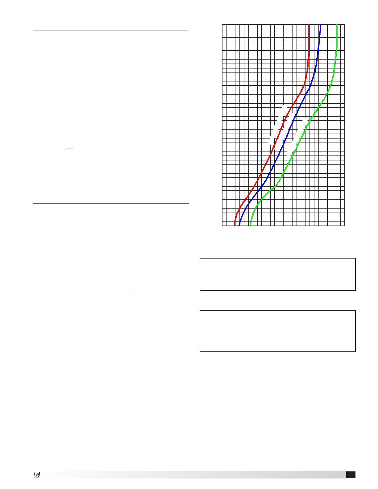
2. Never operate heater without achieving at least
the minimum airflow required. Always refer to
the installation instructions and the nameplate
label to determine minimum air velocities based
on inlet air temperature. If the minimum airflow
requirements are not present the heater will not
function properly and safely
(see Figure 3).
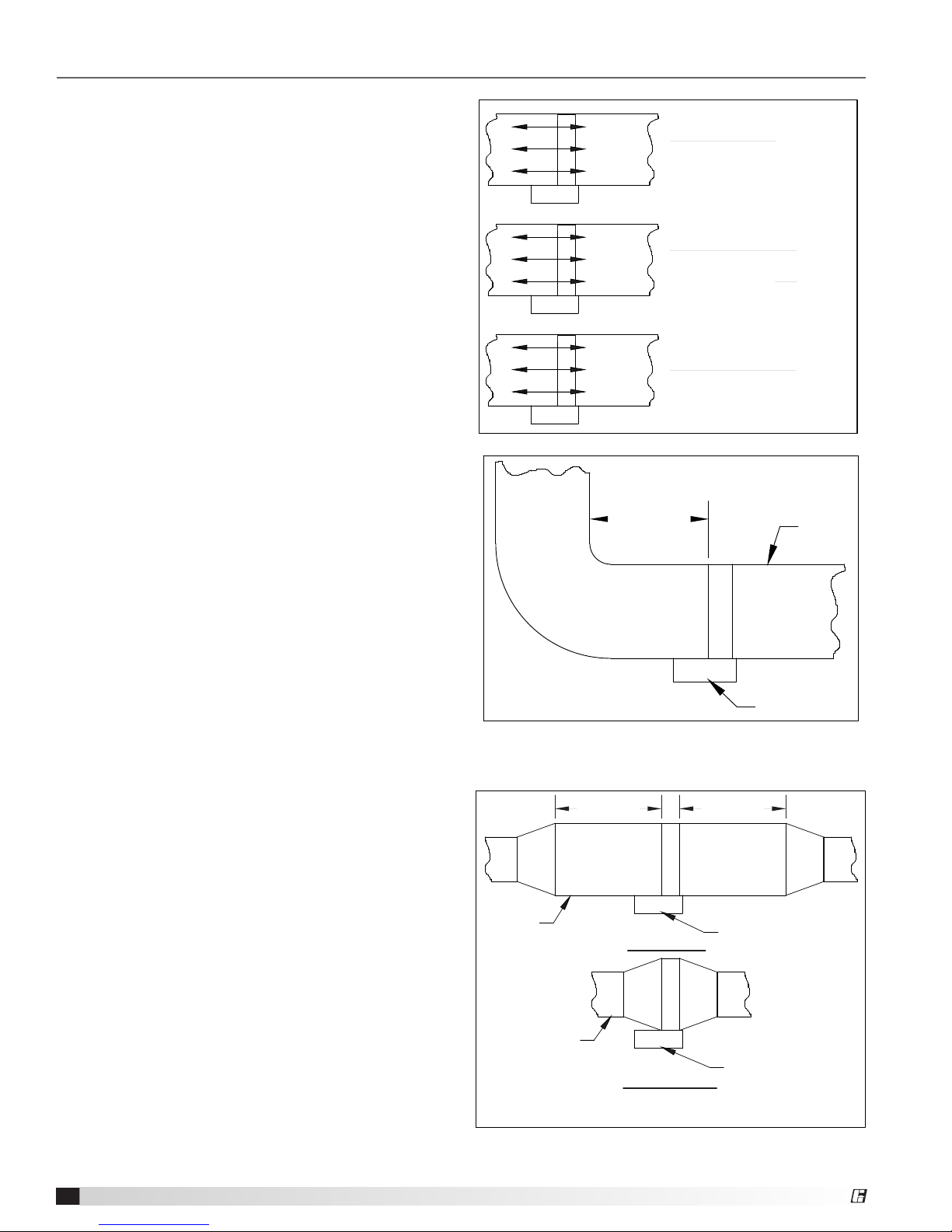
3. Never operate the heater with uneven airflow.
The minimum airflow requirements must be
present at all points over the heater face (see
Figure 3).
4. The air must be filtered. The incoming air must
be free from all debris, combustible particles,
and hazardous vapors.
5. Locate the heater at least 24 in. from an elbow
or turn (see Figure 4).
6. Locate the heater at least 48 in. from the
following (see Figures 5-9):
• heat pump or central air
• canvas duct connector or transition
section for change in duct size.
• downstream from an air handler.
• upstream from a humidifier
• downstream from an air filter
• fan
7. Never install a standard heater into a duct with
an internal obstruction. An obstruction can
block airflow at the temperature limit controls
and element terminations. If this situation
exists, it can be corrected by using a heater
with recessed control box and reduced wrapper
size. This situation is common with internally
insulated ducts (see Figure 10).
8. Never insulate the exterior of the control box.
The control must be completely accessible and
located where ventilation can be provided at all
times (see Figure 11).
9. Never install a heater near a double blower
outlet. A heater must be installed far enough
away from a double blower outlet so that even
and proper airflow is present or separate duct
heaters placed in the duct runouts of each
blower (see Figure 12).
500 fpm
470 fpm
780 fpm
EXAMPLE: IF 780 fpm IS REQUIRED
CORRECT
MIN. AIRFLOW AND EVEN AIR
DISTRIBUTION ARE PRESENT
INCORRECT
MIN. AIRFLOW AND EVEN AIR
DISTRIBUTION ARENOT PRESENT
INCORRECT
MIN. AIRFLOW IS NOT PRESENT
FIG. 3
470 fpm
470 fpm
780 fpm
780 fpm
780 fpm
780 fpm
FIG. 4
FIG. 5
Heat Pump or Air Conditioner
24" MIN.
48" MIN.
HEAT PUMP OR
AIR CONDITIONER
HEATER
HEATER
DUCT
DUCT
INCORRECT
CORRECT
FIG. 5
Transition Change
HEATER
48" MIN. 48" MIN.
HEATER
DUCT
DUCT
6Electric Duct Heaters

Troubleshooting Guide cont....
10. Order the heater with the factory installed
linear temperature limit control if the heater
width is greater than 72 inches.
11. Never use aluminum conductors. Use copper
conductors only for all incoming wiring.
12. Never install a standard heater outdoors with-
out making special provisions to protect the
heater and control box from the elements.
13. Never bundle, tie or wrap power wiring. The
wire could overheat or the insulation could
breakdown.
14. Never use a different voltage and/or phase
than what is listed on the heater nameplate
label. The duct heater is to be used only at the
voltage and phase that is listed on the name-
plate label.
Note: An airflow switch only proves that airflow exists
(a differential in static pressure), not that the
minimum air velocities and proper air distribution
for the duct heater exist.
FIG. 7
Air Handler
FIG. 8
Humidifier
FIG. 9
Air Filter
AIR HANDLER
HEATER
HEATER
HUMIDIFIER
AIR FILTER
HEATER
48" MIN.
48" MIN.
DUCT
DUCT
DUCT 48" MIN.
DUCT W/ INTERNAL INSULATION
DUCT W/ EXTERNAL INSULATION
CORRECT INCORRECT
CORRECT INCORRECT
FIG. 10
FIG. 11
FIG. 12 INCORRECT
7
Electric Duct Heaters

DUCT W/ INTERNAL INSULATION
DUCT W/ EXTERNAL INSULATION
CORRECT INCORRECT
CORRECT INCORRECT
FIG. 10
FIG. 11
FIG. 12 INCORRECT
Troubleshooting Guide cont....
8478052 • IDHB & IDHC, Rev. 3, October 2016 Copyright 2016 © Greenheck Fan Corporation
As a result of our commitment to continuous improvement, Greenheck reserves the right to change specifications
without notice.
Specific Greenheck product warranties are located on greenheck.com within the product area tabs and in the
Library under Warranties.
®
Phone: (715) 359-6171 • Fax: (715) 355-2399 • E-mail: [email protected] • Website: www.greenheck.com
Our Commitment
Other manuals for IDHB
1
This manual suits for next models
1
Table of contents
Other Greenheck Heater manuals