Stelrad ELECTRIC Series User manual

ALU SIMPLE
DRY

Stelrad
UIN Colour Height
mm
Length
mm
Heat output
Power (Watts) Btu/hr
Electric voltage -
Frequency
E01805800600 White 580 600 1000 3414 230V - 50Hz
E01805800840 White 580 840 1500 5121 230V - 50Hz
E01805801080 White 580 1080 2000 6828 230V - 50Hz
E01905800600 Anthracite 580 600 1000 3414 230V - 50Hz
E01905800840 Anthracite 580 840 1500 5121 230V - 50Hz
E01905801080 Anthracite 580 1080 2000 6828 230V - 50Hz
ALU SIMPLE DRY
CLASS 2
INSULATUION
2
Anthracite
grey
Traffic
white
IN STOCK
Integrated control panel
The colour coordinated push button digital control with an LCD display is located on the top right hand side of the radiator.
With numerous functions for efficiency, energy saving and safety in mind
Remote control
A colour coordinated hand held digital remote control is available with wall mounting brackets.
With numerous functions for efficiency, energy saving and safety in mind.
Installation
This radiator must be wall mounted and must not be installed immediately below or in front of a power socket or in contact with the wall
or floor. If installed within a bathroom, the radiator must be mounted outside zone 1 and the switch / electric control must be in zone 3.
For further information, please see the technical information pages.
YEAR WARRANTY
ELECTRIC
COMPONENTS
2
YEAR WARRANTY
HEATING
PARTS
5
ALUMINIUM
ELECTRIC RADIATORS
The Alu Simple Dry is an aluminium radiator encasing a natural stone. Using dry inertia technology, the
radiator heats the air in your rooms via a process of convection with a soft and continuous heat, this
means less energy consumption and quicker heat up times as the internal stone gently adapts to the
desired temperature.
Corrosion resistant with no fluids or chemicals and with no chance of leaks, this has a high energy
efficiency rating due to the stones natural ability to absorb, hold and radiate heat faster and for longer.
This product is LOT20 compliant.

ALU SIMPLE DRY
Positioning and installing
•The appliance is designed to heat domestic rooms or similar. It must not be used for other purposes.
•The appliance must be used permanently mounted on a wall as described in the instructions.
•Install the appliance with the control panel at the top.
•In bathrooms (with bath or shower), install the appliance outside zone 1
•The appliance must be installed in such a way that the electronic controls and other control devices
may not be touched by someone in the bath or shower. The electronic controls and other control
devices must always be in zone 3. The appliance must not be connected with a plug.
•This product comes with a 900mm colour coordinated cable (no plug), so it can be spur wired to the
heating circuit.
•Respect the distances shown.
•Never install the appliance:
- immediately below or in front of a power socket or a junction box
- in contact with the wall or floor
- near curtains, flammable or combustible materials or pressure vessels
•Make sure there are no pipes or electric wires in the wall which could be damaged while mounting
the appliance.
•The appliance is equipped with a sensor which can detect an Open Window, if present above the
radiator or within the room. For a proper operation, it is strongly recommended to comply to the
installation directions reported in Ch. 4.3.1 before wall mounting.
•No need to maintain or service this product once installed. However, should any technical problems
arise, contact a qualified professional or your local dealer. All operations on the appliance must be
carried out by a qualified professional who before performing maintenance must make sure the
appliance is turned off, cold and disconnected from the household mains.
50
Zone 2 Zone 3
Zone 3
Zone 2
Zone 1
Fig. / Abb. 1
Fig. / Abb. 2
Dispositif de commande
FR
Dispositivo de comando
PT
Dispositivo de mando
ES
Control device
EN
Dispositivo di comando
IT
Bedienblende
DE
Fig. / Abb. 3 Fig. / Abb. 4
Fig. / Abb. 5 Fig. / Abb. 6 Fig. / Abb. 7
A
C
B
EF G HD
I
L
Control device
ELECTRIC RADIATORS

ALU SIMPLE DRY
Electrical connection
•You are recommended to have the appliance installed by a qualified professional.
•The appliance must be installed in compliance with national legislation regulating electrical equipment
and installations. When the appliance is installed, make sure the power is off and the mains switch is in
the “O“ position.
•The appliance requires a 230 V ~ 50 Hz power supply. Make sure the power line is appropriate for the
data shown on the appliance’s rating plate.
•Make sure the fixed power line is fitted with a disconnecting switch allowing the appliance to be
disconnected completely from the household mains, included the Pilot Wire, when present, in
accordance with the wiring rules.
If the appliance is installed in a bathroom, the power line must be fitted with a 30 mA RCD (high
sensitivity residual current protection device). The power supply line and Pilot Wire control unit must be
protected by the same RCD. Permanently connected appliances must be connected using a connector
block placed within a proper junction box.
When installing the appliance in damp rooms (kitchen, bathroom), the point of connection with
the household mains must be at least 25 cm from the floor. Respect the wiring diagram in figure 8
scrupulously.
•If the Pilot Wire is not connected to the programming unit, it must be terminated and insulated. Under
no circumstances should the Pilot Wire be connected to the earth.
44
EN
45
3. POSITIONING aND INSTaLLING
The appliance is designed to heat domestic rooms
or similar. It must not be used for other purposes.
The appliance must be used permanently mounted
on a wall as described in the instructions.
Install the appliance with the control panel at the
top (Fig.2).
In bathrooms (with bath or shower), install the ap-
pliance outside zone 1 (Fig. 2).
The appliance must be installed in such a way that
the electronic controls and other control devices
may not be touched by someone in the bath or
shower (Fig. 2). The electronic controls and other
control devices must always be in zone 3. The ap-
pliance must not be connected with a plug.
For radiators with power plugs, see the
warnings on page 56.
Respect the distances shown in gures 3,4.
Never install the appliance:
– immediately below or in front of a power socket or
a junction box (Fig. 5)
– in contact with the wall or oor
– near curtains, ammable or combustible materials
or pressure vessels.
Make sure there are no pipes or electric wires in the
wall which could be damaged while mounting the
appliance.
2. GENERaL INFORmaTION
Unpack the appliance carefully and rest it on the
polystyrene corner pieces or a carpet.
The package contains:
– the appliance
– remote control (if provided) with two batteries and
container for wall mouting
– mounting kit
– instructions
Read all the instructions carefully before installation
and use. Keep for future consultation.
Install and use the appliance as described in these
instructions only.
These instructions do not cover all situations which might
arise. Caution and common sense should be applied
when installing, operating and servicing the appliance.
Modifying the characteristics of the appliance and
removing any xed component including the caps
is expressly prohibited.
Make sure the appliance is complete and undam-
aged. If damaged, do not use the appliance, but
contact your local dealer or a qualied professional.
The materials used for packaging can be recycled. You
are therefore recommended to dispose of them in
special differentiated waste collection containers.
A Brand/Manufacturer
B Model, type, category
C Bidimensional Code (QR)
D Protection class
E CE marking
F Double isolation
G Disposal procedures
H Quality marks
I
L Serial number
3.1 WaLL mOuNTING
Make sure the screws and anchors included in the
mounting pack are suitable for the type of wall
on which you are mounting the appliance. If in
doubt, contact a qualied professional or your lo-
cal dealer.
The installation template is on the back of the box.
Open up the box completely and rest it against the
wall. Follow the installation sequence shown on
the folding leaf of the cover (Scheme 1), respecting
the minimum distance between the bottom of the
radiator and the oor (Fig. 3).
The technical specications of the appliance are
indicated on the rating plate on the side of the ra-
diator (Fig. 1).
1. SPEcIFIcaTIONS OF ThE aPPLIaNcE
Voltage: 230 V ~ 50 Hz
Insulation class:
II
Protection class: IP24
Power [W] Length [cm] Height
[cm]
Weight
[kg]
Rated current
[A]
700 52 58 15 3
1000 60 58 18 4,5
1500 84 58 25 6,5
2000 108 58 33 9
Table 1
Voltage and Power
The appliance is equipped with a sensor which
can detect an Open Window, if present above the
radiator or within the room. For a proper opera-
tion, it is strongly recommended to comply to the
installation directions reported in Ch. 4.3.1 before
wall mounting.
ELECTRIC RADIATORS

ALU SIMPLE DRY
Control Panel Display
46
EN
47
To turn the appliance on or off, press the
“Standby” button.
The radiator turns on in the previously selected operating
mode and emits a sound.
In “Chrono“ mode the display shows the time, in the other
4.1 ON/STaNDBy mODE
In “Standby” mode, is displayed: “Stby“. All the
operating modes are suspended (“Pilot Wire“
included), but the appliance is powered and
waiting for command reception.
cONTROL
PaNEL
ON/Standby key
Infrared Receiver
“Mode“ selection key
“+“ and “-“ key
DISPLay
Chrono temperature Set
Operating modes
Children Safety
Days of the Week
Keypad Lock
Clock / Temperature set
point
Heating element stateChrono program time bar
uSING ThE RaDIaTOR FROm ThE cONTROL PaNEL:
Signal transmission from the remote control (if provided) to the radiator.
46
EN
47
To turn the appliance on or off, press the
“Standby” button.
The radiator turns on in the previously selected operating
mode and emits a sound.
In “Chrono“ mode the display shows the time, in the other
4.1 ON/STaNDBy mODE
In “Standby” mode, is displayed: “Stby “. All the
operating modes are suspended (“Pilot Wire“
included), but the appliance is powered and
waiting for command reception.
cONTROL PaNEL
ON/Standby key
Infrared Receiver
“Mode“ selection key
“+“ and “-“ key
DISPLay
Chrono temperature Set
Operating modes
Children Safety
Days of the Week
Keypad Lock
Clock / Temperature set
point
Heating element stateChrono program time bar
uSING ThE RaDIaTOR FROm ThE cONTROL PaNEL:
Signal transmission from the remote control (if provided) to the radiator.
Operating modes (for the Control Panel and Remote Control)
Pilot Wire (n/a in the UK) Comfort Night / Eco Anti-freeze Chrono
Standby
Functions (for the Control Panel and Remote Control)
Open window Child safety Override Keypad lock
Remote control
The radiator can also be programmed with the infrared
remote control, included in the packaging.
The remote control communicates with the appliance
by infrared rays. For efficient communication, point the
remote control at the receiver on the appliance.
The distance between the remote control and the receiver
must not be more than 5m.
Always handle the remote control with great care and place
it within the special plastic container for wall mounting,
included in the packaging.
Do not drop the remote control nor leave it exposed to direct
sunlight. Do not spray water or other liquids onto the remote
control. Do not rest the remote control on the top of the
radiator or near other intense sources of heat.
50
EN
51
The remote control communicates with the appliance by in-
frared rays. For efcient communication, point the remote
control at the receiver on the appliance (Fig. 10).
The distance between the remote control and the receiver
must not be more than 5 m.
Always handle the remote control with great care and place
it within the special plastic container for wall mounting, in-
cluded in the packaging.
Do not drop the remote control nor leave it exposed to direct
sunlight. Do not spray water or other liquids onto the remote
control. Do not rest the remote control on the top of the ra-
diator or near other intense sources of heat.
Size 100 x 42 x 20,5 mm
Power supply “AAA“ LR03 1.5 V alkaline
batteries
Characteristics:
Inserting or replacing the batteries:
• Remove the cover on the back of the remote control.
• Insert two “AAA“ LR03 1.5 V alkaline batteries in the
correct position.
• Put the cover back.
When replacing the batteries or disposing of the remote
control, the batteries must be removed and disposed of in
compliance with current legislation as they are harmful to
the environment.
5 m MAX
4.4 INFRaRED REmOTE cONTROL
OPERaTION WIThREmOTE cONTROL uNIT
(IF PROvIDED)
The radiator can also be programmed with the in-
frared remotr control, included in the packaging.
To unlock the keypad, press the same two buttons together
as before.
The “Keypad Lock“ icon will no longer appear on the LCD.
ImPORTaNT:The “Keypad Lock” function does
not inhibit the “Standby” button. This is therefore
always active, even when the “Keypad Lock” func-
tion is enabled.
4.3.4 KEyPaD LOcK
It is possible to lock the keypad to prevent accidental mo-
dications.
To activate the function, press the “Mode”
and “+” buttons together and hold them both
down until the icon appears on the dis-
play.
Fig. 10
50
51
EN
REmOTE cONTROL
Display LCD
“+“ key“-“ key
Fan Heater key“Mode“ selection key
ON/Standby keyOverdrive (2h) key
DISPLay
Fan Heater
Clock
Chrono temperature Set
Chrono program time bar
Days of the Week
Keypad Lock
Chrono presets
Overdrive (2h)
Children Safety
Signal broadcast
Temperature set point/Fan heater timer
Operating modes
Signal transmission from the remote control (if provided) to the radiator.
ELECTRIC RADIATORS
This manual suits for next models
7
Table of contents
Other Stelrad Heater manuals
Stelrad
Stelrad Regal User manual
Stelrad
Stelrad LECCO User manual
Stelrad
Stelrad ELECTRIC Series User manual
Stelrad
Stelrad Alyne GYA0610F User manual
Stelrad
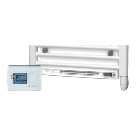
Stelrad E-VENTO 0184B0002 Guide

Stelrad
Stelrad ELECTRIC Series User manual

Stelrad
Stelrad ELECTRIC Series User manual

Stelrad
Stelrad ELECTRIC Series User manual

Stelrad
Stelrad ELECTRIC Series User manual

Stelrad
Stelrad ELECTRIC Series User manual
