ORTEC radEAGLE User manual

radEAGLE
User Manual
Software 3.2.12 • Document 3.3.0o • 2019-04-11

ORTEC
801 South Illinois Avenue
Oak Ridge, TN 37830
U. S. A.
+1 865 482 4411
+1 865 483 0396
mailto:[email protected]
http://www.ortec-online.com/contactus/technicalsupport
radEAGLE™is a trademark of innoRIID GmbH.
innoRIID®is a registered trademark of innoRIID GmbH in most jurisdictions.
All other trademarks belong to their respective holders.
Copyright © 2015–2019 innoRIID GmbH. All rights reserved.

Contents
1 Welcome 11
1.1 Conventions Used in This Document ...................... 11
1.2 Safety Warnings ................................. 11
1.3 Instrument Safety ................................. 12
1.4 Before First Use ................................. 12
1.5 The radEAGLE ................................... 13
1.5.1 Detectors ................................ 13
1.5.1.1 Scintillation Detector .................... 13
1.5.1.2 Geiger-Müller Detector ................... 13
1.5.1.3 Neutron Detector ...................... 14
1.5.2 Overview ................................. 14
1.5.3 Hardware Accessories ......................... 16
1.5.4 Connectors ................................ 19
2 Using the radEAGLE 21
2.1 The radEAGLE Display .............................. 21
2.1.1 Status LEDs ............................... 23
2.2 Using the radEAGLE Keys ............................ 23
2.2.1 Using Command Lists .......................... 25
2.2.2 Using Menus ............................... 25
2.2.3 Changing Values ............................. 26
2.2.4 Entering the Password ......................... 26
2.2.5 Saving Screenshots ........................... 28
2.3 Starting Up the radEAGLE ............................ 29
2.4 Switching Off the radEAGLE ........................... 30
3radEAGLE Measuring Modes 31
3.1 Dose Rate Mode ................................. 31
3.2 Easy ID Mode ................................... 33
3.3 Detect Mode ................................... 34
4radEAGLE Warnings and Alarms 37
4.1 Gamma Warning and Alarm Display ...................... 38
4.1.1 Neutron Alarm Display ......................... 39
© innoRIID GmbH • 2019-04-11 Software 3.2.12 • Document 3.3.0o 3/147

CONTENTS radEAGLE User Manual
5radEAGLE Advanced Menu 41
5.1 Spectrum ..................................... 42
5.2 Basic Settings ................................... 47
5.3 Time and Date ................................... 48
5.4 Display ....................................... 49
5.5 Feedback ..................................... 50
5.6 Reachback ..................................... 51
5.7 Connectivity .................................... 52
5.8 Wi-Fi Settings ................................... 52
5.9 Hotspot Settings ................................. 54
5.10 Bluetooth Settings ................................ 56
5.11 USB Connections ................................. 57
5.11.1 USB Cable to Host Computer ..................... 58
5.11.2 USB Storage Device ........................... 59
5.11.3 USB Ethernet Adaptor ......................... 60
5.12 Services ...................................... 61
5.13 GPS ........................................ 62
5.14 Easy Calibration .................................. 63
5.15 Protected Settings ................................ 65
5.16 System Information ................................ 66
5.17 Alarm Settings .................................. 66
5.18 Calibration ..................................... 68
5.19 ID Settings ..................................... 69
5.20 Easy ID Settings .................................. 69
5.21 Nuclide Library .................................. 70
5.22 Storage Management .............................. 72
5.23 Set Password ................................... 75
5.24 Factory Settings ................................. 76
5.25 Collect Reachback ................................ 76
5.26 Send Data ..................................... 78
5.27 Self Test ...................................... 80
5.28 About ........................................ 81
5.29 Shutdown ..................................... 82
6 Accessing radEAGLE Data 83
6.1 Storage Management .............................. 83
6.2 Data Transfer ................................... 83
6.3 Web Interface ................................... 84
6.4 Sending Data via E-Mail ............................. 84
4/147 Software 3.2.12 • Document 3.3.0o © innoRIID GmbH • 2019-04-11

radEAGLE User Manual CONTENTS
7radEAGLE Web Interface 85
7.1 Device Info ..................................... 86
7.2 Wi-Fi Hotspot ................................... 86
7.3 Remote Screen .................................. 88
7.4 Spectrum Browser ................................ 88
7.4.1 Spectrum Inspector ........................... 89
7.4.1.1 Spectrum Diagram ..................... 90
7.4.1.2 Manual Peak Analysis .................... 92
7.4.1.3 Automatic Peak Analysis .................. 92
7.4.1.4 Spectrum Details ...................... 95
7.4.1.5 PDF Report Creation .................... 97
7.5 Spectrum File Viewer ............................... 99
7.6 Device Settings .................................. 99
7.7 Reachback Settings ............................... 100
7.8 Software Update ................................. 103
7.9 Documents .................................... 104
7.10 Storage Management .............................. 104
8 Powering the radEAGLE 107
8.1 radEAGLE Battery Packs ............................ 107
8.1.1 Black powerCELL ............................ 107
8.1.2 Blue powerCELL ............................. 107
8.2 Replacing Batteries of the radEAGLE ...................... 109
8.2.1 Standard Enclosure ........................... 109
8.2.2 Underwater Enclosure ......................... 111
8.3 External Power Sources ............................. 113
8.3.1 Wall Power Supply ............................ 114
8.4 Charging the powerCELL ............................ 116
8.5 Energy Saving Tips ................................ 117
Appendix 119
A Nuclide Library 119
B Glossary 125
C Technological Background, Limitations 127
C.1 Stabilization .................................... 127
C.1.1 Initial Stabilization ............................ 127
C.1.2 Continuous Temperature Monitoring ................. 127
C.1.3 Continuous Spectroscopic Adjustments ............... 127
© innoRIID GmbH • 2019-04-11 Software 3.2.12 • Document 3.3.0o 5/147

CONTENTS radEAGLE User Manual
C.2 Calibration ..................................... 128
C.2.1 Checking the Calibration ........................ 128
C.2.2 Re-Calibrating Using the Calibration Mode .............. 128
C.3 Effective Range of Measurement ........................ 129
C.4 Determination of the Full Width at Half Maximum .............. 129
C.5 Over-Range Characteristics for the Scintillator and the Nuclide Identification 129
C.6 Live, Real and Dead Times ............................ 130
C.7 Scaling of the Vertical Spectrum Axis ..................... 130
D Troubleshooting 131
D.1 The Stabilization Icon is Red ........................... 131
D.2 System Switches Back to Black Screen .................... 131
D.3 System Keeps Running Although the Battery Switch is Set to Off . . . . . . 131
D.4 Checking the Proper Function of the System ................. 132
E Info Pool 135
E.1 ınnoRIID radEAGLE: Specifications ....................... 135
E.2 Detector Positions ................................ 141
E.3 About Intrinsic Activity .............................. 143
E.3.1 General Rules for Handling Radioactive Material ........... 143
E.3.2 For the United States of America ................... 143
E.4 Unmanned Neutron Detection Testing ..................... 144
E.5 CE Certificate ................................... 145
E.6 Warranty ..................................... 146
E.7 Quality Control .................................. 146
E.8 Service ....................................... 146
E.9 Damage in Transit ................................ 147
E.10 Bibliography .................................... 147
6/147 Software 3.2.12 • Document 3.3.0o © innoRIID GmbH • 2019-04-11

List of Figures
1 Annotated top view of the radEAGLE instrument ................. 14
2a Rear view of the radEAGLE with open latch (standard housing) ......... 15
2b Rear view of the radEAGLE with open battery compartment (underwater housing) 15
3 Name plate on the rear latch of the radEAGLE .................. 15
4 The radEAGLE in the standard case ........................ 16
5 The radEAGLE in an optional watertight case ................... 17
6 The radEAGLE with accessories ........................... 17
7 Standard (left) and optional watertight cases for the radEAGLE ......... 18
8 Anatomy of the radEAGLE display .......................... 21
9 The current functions of keys shown along the bottom of the radEAGLE display. 24
10 Cycling command pairs ................................ 25
11 A menu with the third item accented ........................ 25
12 Changing switches .................................. 26
13 Changing values by choosing from a list ...................... 26
14 Entering the password ................................ 27
15 After entering the password ............................. 27
16 Status bar after saving a screenshot ........................ 28
17 Box with potassium chloride (KCl) for stabilization and calibration ........ 29
18 Starting the radEAGLE ................................ 29
19 Initial stabilization ................................... 30
20 Initial Stabilization after identification of the stabilization source ......... 30
21 Dose rate display ................................... 31
22 Dose rate display with gamma warning ....................... 32
23 Dose rate display with gamma alarm ........................ 32
24 The Easy ID screen .................................. 33
25 The Easy ID results .................................. 33
26 Detect mode background measurement ...................... 34
27 Detect mode chart .................................. 35
28 Detect mode: Approaching a source ........................ 35
29 Detect mode: Close to a source ........................... 36
30 A warning reported on screen ............................ 38
31 An alarm reported on screen ............................ 38
32 An neutron alarm reported on screen ....................... 39
© innoRIID GmbH • 2019-04-11 Software 3.2.12 • Document 3.3.0o 7/147

List of Figures radEAGLE User Manual
33 The advanced operations menu ........................... 42
34 The spectrum screen ................................. 43
35 Result of a spectrum analysis ............................ 43
36 Spectrum with cursor ................................ 44
37 Zoomed spectrum with cursor ........................... 44
38 Spectrum with Region Of Interest .......................... 45
39 Info about a saved spectrum’s file name ...................... 45
40 Spectrum files available for loading ......................... 46
41 The Auto ID Waterfall display ............................ 47
42 The basic settings menu ............................... 47
43 The clock settings ................................... 48
44 The display settings .................................. 49
45 The feedback settings ................................ 50
46 The reachback settings ................................ 51
47 The connectivity menu ................................ 52
48 The Wi-Fi settings ................................... 53
49 Available Wi-Fi access points ............................. 53
50 Connected to a Wi-Fi network ............................ 54
51 Hotspot is off ..................................... 55
52 Hotspot: Web interface info ............................. 55
53 Hotspot: Access credentials ............................. 56
54 Bluetooth settings .................................. 56
55 Bluetooth instructions on a pristine radEAGLE .................. 57
56 Connect to a known Bluetooth device ........................ 57
57 Web interface address for devices connected via Bluetooth ........... 58
58 USB cable connection information ......................... 58
59 Data transfer to a USB mass storage device ................... 59
60 Data transfer complete ............................... 60
61 Ethernet LAN connection information ....................... 60
62 The services screen ................................. 61
63 The GPS settings when GPS is off .......................... 62
64 The GPS settings immediately after switching on GPS .............. 62
65 The GPS settings while searching satellites .................... 63
66 The GPS settings after determinig the location .................. 63
67 Selecting a source for easy calibration ....................... 64
68 Easy calibration in progress ............................. 64
69 Easy calibration finished ............................... 65
70 The protected settings menu ............................ 65
71 The hardware status ................................. 66
72 The alarm settings .................................. 67
73 The calibration screen ................................ 68
8/147 Software 3.2.12 • Document 3.3.0o © innoRIID GmbH • 2019-04-11

radEAGLE User Manual List of Figures
74 The calibration screen after measurement .................... 68
75 The ID settings menu ................................. 69
76 The easy ID settings ................................. 70
77 The nuclide library ready for selecting a nuclide .................. 70
78 The nuclide library with 131I selected for editing its category ........... 71
79 The nuclide library with 131I selected for editing its On/Off property . . . . . . 72
80 Storage management: Summary .......................... 73
81 Storage management: List of folders with different types of data ........ 73
82 Storage management: Commands for a type of data ............... 74
83 Storage management: List of files of a certain type ................ 74
84 Storage management: Specify files to be deleted ................. 75
85 Setting the password ................................. 75
86 Reset to factory settings ............................... 76
87 Settings for a new measurement .......................... 77
88 Collecting reachback data .............................. 77
89 Collected measurements ............................... 78
90 Checking the Internet connection .......................... 78
91 No Internet connection ................................ 79
92 File types for mailing ................................. 79
93 Selecting files ..................................... 80
94 Ready to send files .................................. 80
95 The self test screen .................................. 80
96 The instrument information ............................. 82
97 Shut down verification ................................ 82
98 The menu overlay of the Web interface ....................... 85
99 The device information in the Web interface .................... 86
100 The Wi-Fi hotspot info in the Web interface (off) .................. 86
101 The Wi-Fi hotspot info in the Web interface (on) .................. 87
102 The remote radEAGLE’s screen in the Web interface .............. 88
103 The spectrum browser in the Web interface ................... 89
104 Spectrum diagramm in the Web interface ..................... 90
105 Zooming into the spectrum ............................. 91
106 Enlarged part of the spectrum ............................ 91
107 Marking a peak for analysis ............................. 92
108 Results for a manually marked peak ......................... 93
109 Results of an automatic peak analysis ....................... 94
110 Spectrum with scaling methods and detail overview ............... 95
111 Spectrum with expanded detail information .................... 96
112 Comment subsection of spectrum details ..................... 97
113 PDF report of a spectrum .............................. 98
© innoRIID GmbH • 2019-04-11 Software 3.2.12 • Document 3.3.0o 9/147

List of Figures radEAGLE User Manual
114 The spectrum file viewer in the Web interface ................... 99
115 The radEAGLE settings in the Web interface ................... 99
116 The reachback settings in the Web interface ................... 100
117 The expanded reachback settings in the Web interface ............. 101
118 Adding a recipient for reachback messages .................... 102
119 Update software on the radEAGLE in the Web interface ............. 103
120 Transfer software to the radEAGLE in the Web interface ............ 103
121 Ready to install the transferred software ..................... 103
122 Successful installation of the software ....................... 104
123 Documents available on your radEAGLE ...................... 104
124 Managing the storage in the Web interface .................... 105
125 The standard black rechargeable powerCELL of the radEAGLE.......... 107
126 The blue powerCELL for common batteries. .................... 108
127 The blue powerCELL filled with batteries. ..................... 108
128 Orientation of AA bateries in the blue powerCELL (shown without cover). . . . 108
129 Pulling the protection of the power connector ................... 109
130 Opening the rear latch of the radEAGLE ...................... 109
131 Removing the powerCELL from the radEAGLE .................. 110
132 Inserting a powerCELL ................................ 110
133 Snapping the powerCELL into place ......................... 111
134 The powerCELL correctly mounted in the radEAGLE................ 111
135 powerCELL in the radEAGLE after removing the cover .............. 112
136 Removing the powerCELL with gravity assistance ................ 112
137 Inserting the powerCELL ............................... 113
138 Correct placement of the O-ring seal on the inner side of the cover plate . . . 113
139 Correct placement of the battery cover plate ................... 113
140 Inserting the external power plug .......................... 114
141 Unplugging the external power connection ..................... 114
142 Do NOT rotate the connector, do NOT bend or pull at the power cable! . . . . 115
143 Wall power supply with international adaptors ................... 115
144 Removing an adaptor from the wall power supply ................. 116
145 Mounting an adaptor to the wall power supply ................... 116
146aPosition of the detector centers of the radEAGLE (2 or 3 in×1 in scintillator,
drawn to scale) .................................... 141
146bPosition of the detector centers of the radEAGLE (3 in×0.8 in scintillator, drawn
to scale) ........................................ 142
10/147 Software 3.2.12 • Document 3.3.0o © innoRIID GmbH • 2019-04-11
1 Welcome
This chapter offers introductory information about this manual, some important advice for
your safety and that of the instrument, and an overview of the radEAGLE, its accessories,
and applications.
1.1 Conventions Used in This Document
This document uses the following conventions to signify various kinds of text.
Ordinary Text
looks like this, sometimes bold or
italics
is used for emphasis.
Constant Width
is used for file names, path names, Internet links, or text you have to enter somewhere.
Indicates a specific danger to yourself, your data, or the instrument. Please make
sure you carefully read these passages.
Information you should carefully consider before proceeding.
Important information you should pay attention to.
Suggested commands or procedures for advanced usage. You might skip these tips
on your first pass through this document.
Information related to optional features not applicable to all models of the radEAGLE.
If you read this document as a PDF file, you can click cross references, items in the
table of contents, links into the Internet or similar, to immediately view the designated
item.
1.2 Safety Warnings
The radEAGLE is designed for outdoor use. When operated in accordance with the operat-
ing instructions, it should not present any hazard to the operator.
The radEAGLE is not certified for use in explosive environments.
Do not unscrew the housing of the radEAGLE. There are no user servicable parts
inside.
Various components inside the radEAGLE use high voltages posing a severe health
risk for you.
© innoRIID GmbH • 2019-04-11 Software 3.2.12 • Document 3.3.0o 11/147

1.3 Instrument Safety radEAGLE User Manual
The power adaptor is connected to line power. Normal care in handling such a line
power device should be exercised. In particular this unit should not be connected to
line power if it is wet.
The nature of the application is such that objects you survey with the radEAGLE could
emit ionizing radiation with hazardous intensity.
1.3 Instrument Safety
The detector crystals built into in the radEAGLE are brittle. To enjoy a long-lasting
performance of your instrument, avoid drops or other severe impacts.
Detector crystals may fracture under rapid temperature change. This could occur, for
example, when transporting the instrument in a air-conditioned vehicle and unloading
it in extremeley cold or hot environments. Sudden temperature change must not
exceed 30.0 °C (54.0 °F) in order to avoid damages.
1.4 Before First Use
We recommend charging the batteries of the radEAGLE after unpacking prior to first
time use (8.4, p. 116).
This is a good time to get familiar with the radEAGLE by reading this manual.
Please read at least the rest of this chapter and those on basic operation (chapter 2,
p. 21) before starting to experiment with the radEAGLE.
Chapter 2, p. 21 explains the principles of operating the radEAGLE.
The fundamental modes of operation of the radEAGLE are detailed in chapter 3, p. 31, fol-
lowed by explanations of the radEAGLE alarms in chapter 4, p. 37.
A detailed reference on all the commands is given in chapter 5, p. 41, which you should read
to know about all the features and possibilities in case you need them.
The web interface for monitoring, configuring and transferring data is detailed in chapter 7,
p. 85.
Chapter 8, p. 107 details the power supply for the radEAGLE and the handling of various
battery types.
The appendix comprises
• information about the nuclides the radEAGLE can identify (Appendix A, p. 119),
• a glossary of terms and technological background (Appendix B, p. 125 and C, p. 127)
• a trouble shooting guide (Appendix D, p. 131)
• an info pool (Appendix E, p. 135) with certificates, specification data etc.
12/147 Software 3.2.12 • Document 3.3.0o © innoRIID GmbH • 2019-04-11

radEAGLE User Manual Welcome
Several models of the radEAGLE are available (see E.1, p. 135 for details), all of which
are covered in this document. The few cases where a feature of a certain model
differs from the main stream are marked in the text.
1.5 The radEAGLE
The radEAGLE is a new generation radio-isotope identification device (RIID). It consists of
the following components:
• Scintillation detector using either a sodium iodide NaI(Tl), a lanthanum bromide
LaBr3(Ce), or a cerium bromide CeBr3crystal.
• Geiger-Müller detector
3He Neutron detector
• Multi-Channel Analyzer (MCA) for spectral data readout of the scintillation detector
• Computational subsystem that includes LCD screen, keyboard, status LEDs, vibrator
and speaker
GPS Receiver
1.5.1 Detectors
Each component has a dedicated purpose. The scintillator is the primary detector of the
instrument and would be used for multiple purposes including pulse height analysis and dose
rates.
1.5.1.1 Scintillation Detector
The scintillation detector is used to collect the pulse height spectrum of the gamma photons
that interact with the scintillation crystal. The different radioisotopes each have specific
decay schemes and some emit gamma photons that can be analyzed and used to determine
the radiation source. (ÞScintillation Detector)
1.5.1.2 Geiger-Müller Detector
The dose rate is determined by either the scintillation detector or the internal Geiger-Müller
tube. When the dose rate at the scintillator surface exceeds 200 µSv/h, the Geiger-Müller
tube will perform the dose rate measurement. This tube is suited for measuring dose rates
up to 1 Sv/h. (ÞGeiger-Müller detector)
If the Geiger-Müller detector kicks in, you are already in an extremely dangerous level
of radiation. You should increase distance and shielding between yourself and the
source. Additionally, you should restrict the time you stay within this field to an abso-
lute minimum.
© innoRIID GmbH • 2019-04-11 Software 3.2.12 • Document 3.3.0o 13/147
1.5 The radEAGLE radEAGLE User Manual
1.5.1.3 Neutron Detector
This item is available for radEAGLE models with a neutron detector (see E.1, p. 135).
The 3He neutron detector continuously runs and acquires the current neutron counts per
second (cps) (ÞNeutron Detector).
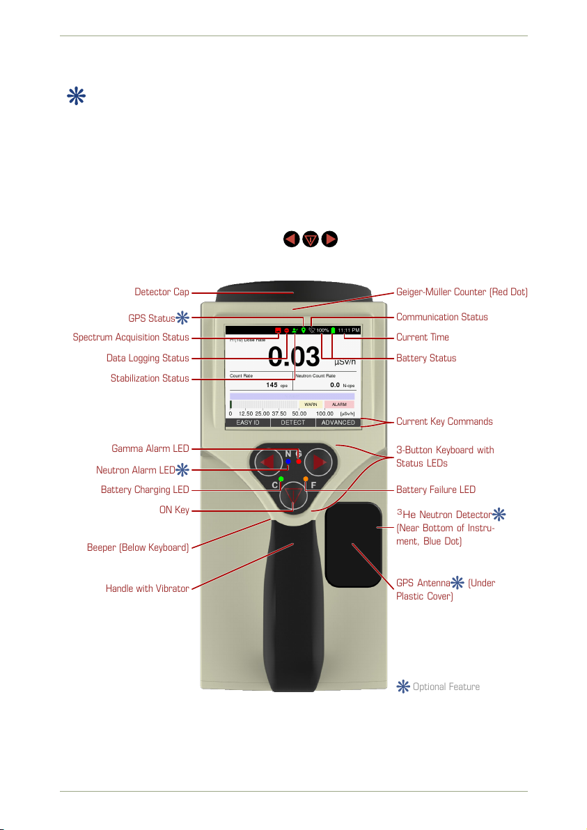
1.5.2 Overview
Fig. 1, p. 14 shows a top view on the radEAGLE instrument. The radEAGLE features a 3.5 in
(89 mm) color display presenting the various screens of the software.
The keyboard below the screen has 3 keys ( ) you can press with your thumb while
holding the instrument.
Detector Cap Geiger-Müller Counter (Red Dot)
Handle with Vibrator GPS Antenna (Under
Plastic Cover)
Beeper (Below Keyboard)
Current Time
Battery Status
Communication Status
GPS Status
Stabilization Status
Data Logging Status
Spectrum Acquisition Status
Current Key Commands
3-Button Keyboard with
Status LEDs
Battery Failure LED
Gamma Alarm LED
Neutron Alarm LED
Battery Charging LED
ON Key 3He Neutron Detector
(Near Bottom of Instru-
ment, Blue Dot)
Optional Feature
Figure 1: Annotated top view of the radEAGLE instrument
14/147 Software 3.2.12 • Document 3.3.0o © innoRIID GmbH • 2019-04-11
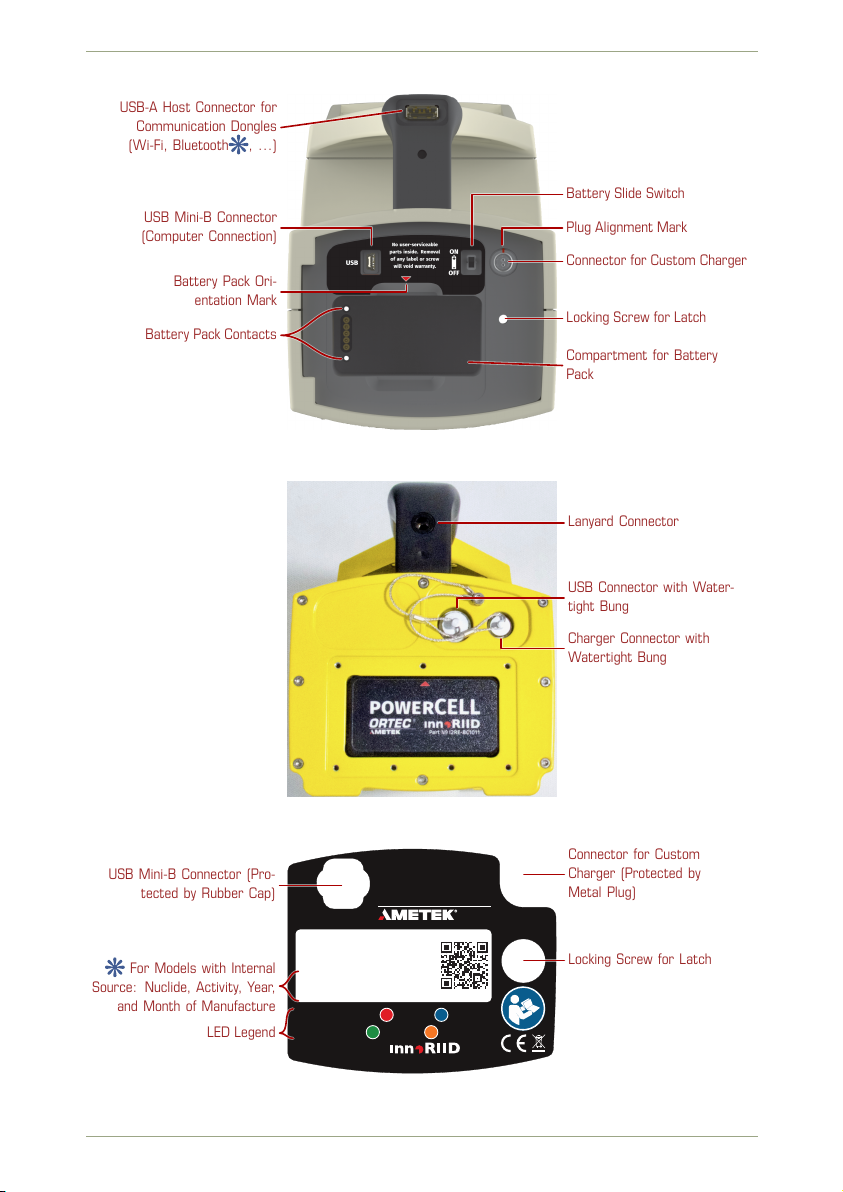
radEAGLE User Manual Welcome
USB-A Host Connector for
Communication Dongles
(Wi-Fi, Bluetooth , …)
USB Mini-B Connector
(Computer Connection)
Battery Pack Ori-
entation Mark
Battery Pack Contacts
Battery Slide Switch
Plug Alignment Mark
Connector for Custom Charger
Locking Screw for Latch
Compartment for Battery
Pack
Figure 2a: Rear view of the radEAGLE with open latch (standard housing)
Lanyard Connector
USB Connector with Water-
tight Bung
Charger Connector with
Watertight Bung
Figure 2b: Rear view of the radEAGLE with open battery compartment (underwater housing)
EAGLE™
Model: RE-3SGI-H-GPS
Serial: 18181
Contains radioactive 137Cs
Activity: 111Bq =3 nCi [2018-11]
Warnings, Alarms: G Gamma N Neutrons
Battery Status: C Charging Heat ailure
Made in Germany by
CHARGERUSB
ORTEC®
USB Mini-B Connector (Pro-
tected by Rubber Cap)
Locking Screw for Latch
Connector for Custom
Charger (Protected by
Metal Plug)
For Models with Internal
Source: Nuclide, Activity, Year,
and Month of Manufacture
LED Legend
Figure 3: Name plate on the rear latch of the radEAGLE
© innoRIID GmbH • 2019-04-11 Software 3.2.12 • Document 3.3.0o 15/147
1.5 The radEAGLE radEAGLE User Manual
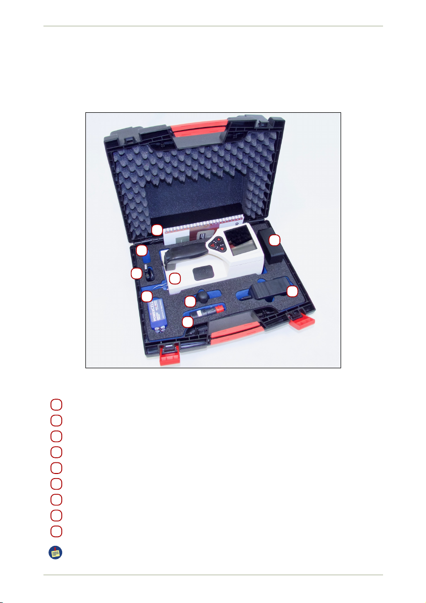
1.5.3 Hardware Accessories
The radEAGLE is delivered with comprehensive accessories. The list of accessories may
vary depending on what is ordered with the system. The transportation case should contain
the following items (Fig. 4, p. 16, Fig. 5, p. 17, Fig. 6, p. 17):
A
B
C
D
EE
F
G
H
Figure 4: The radEAGLE in the standard case
AradEAGLE instrument
B KCl Calibration box
C Charger with US or European plug
c International adaptors for Charger (not with all instruments)
D Power adaptor for cars (12 V)
E Extra Battery pack for AA batteries (with screw driver)
F USB cable for connecting the radEAGLE to a PC
G Documents (manual, quick reference card, test sheet)
H USB Stick
Please make sure the delivered parts are complete.
16/147 Software 3.2.12 • Document 3.3.0o © innoRIID GmbH • 2019-04-11

radEAGLE User Manual Welcome
A
B
C
D
E
E
F
G
H
Removeable Inset
Above Compartment
for International Adap-
tors for Charger [C]
Figure 5: The radEAGLE in an optional watertight case
A
B
C
c c c D
E F
G
Figure 6: The radEAGLE with accessories
© innoRIID GmbH • 2019-04-11 Software 3.2.12 • Document 3.3.0o 17/147
1.5 The radEAGLE radEAGLE User Manual
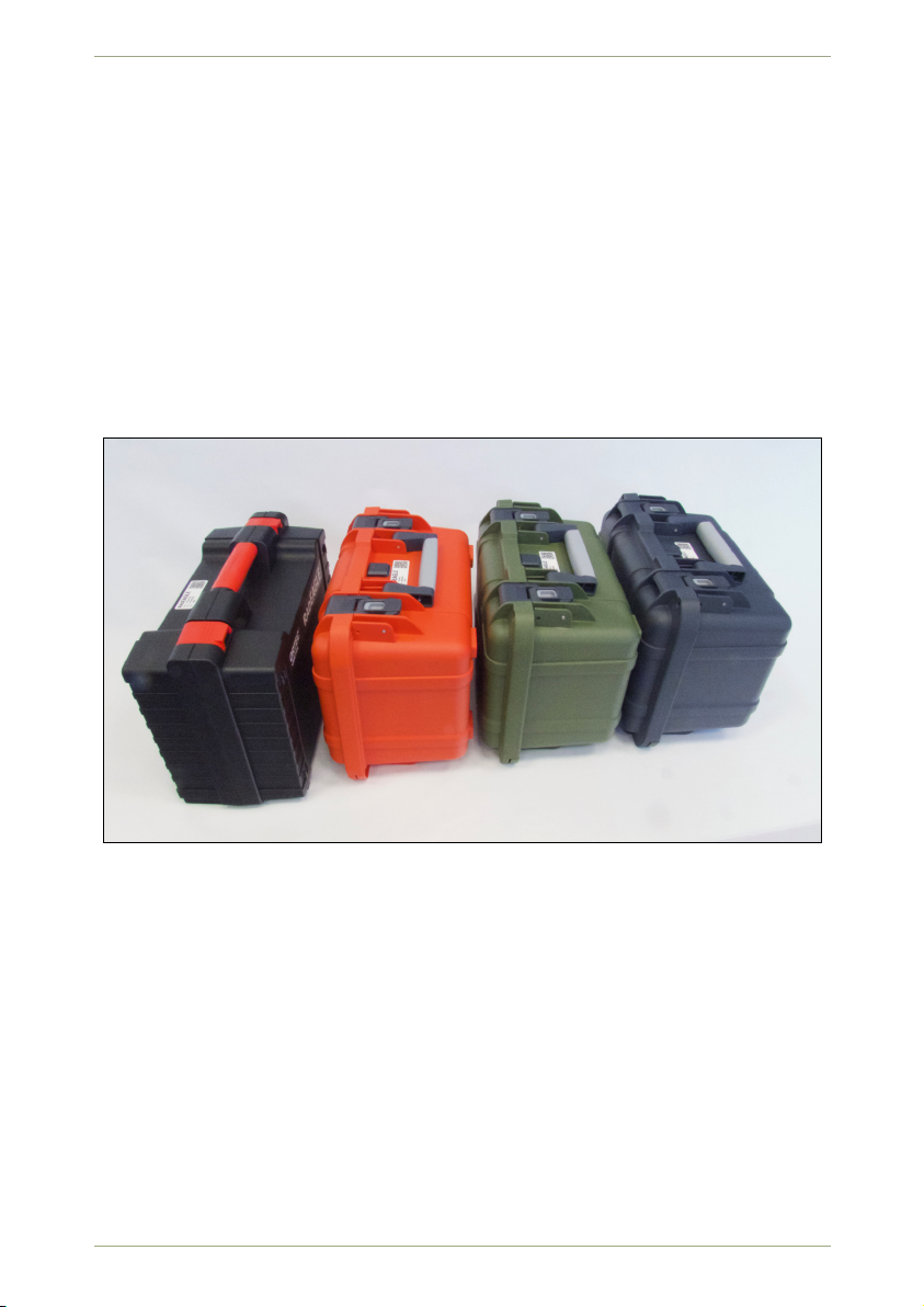
Figure 7: Standard (left) and optional watertight cases for the radEAGLE
18/147 Software 3.2.12 • Document 3.3.0o © innoRIID GmbH • 2019-04-11

radEAGLE User Manual Welcome
1.5.4 Connectors
The radEAGLE has several connectors.
When operating under harsh conditions, keep the connectors clean and free of dust
or sand. If you experience connection problems, clean the connector with a cleanser
specialized for electronic components.
USB Mini-B at rear end
Use this plug (Fig. 2a, p. 15, Fig. 2b, p. 15) to connect your radEAGLE to a computer. All
common operating systems like Microsoft Windows, MacOS or Linux are supported.
USB-A host connector in the handle
Use this plug (Fig. 2a, p. 15) for Wi-Fi, Bluetooth, USB-to-Ethernet adaptors, or USB
storage devices (all optional).
Power plug on back side
Please align the red dot on the charger cable to that of the plug when connecting
(Fig. 2a, p. 15, Fig. 2b, p. 15, Fig. 140, p. 114).
© innoRIID GmbH • 2019-04-11 Software 3.2.12 • Document 3.3.0o 19/147

20/147 Software 3.2.12 • Document 3.3.0o © innoRIID GmbH • 2019-04-11
Table of contents
Popular Metal Detector manuals by other brands


White’s Electronics
White’s Electronics Classic III Plus instruction manual

Steinberg Systems
Steinberg Systems SBS-MD-20 user manual

Bounty Hunter
Bounty Hunter Fortune Hunter owner's manual

Thermo Scientific
Thermo Scientific Apex Service guide

Insportline
Insportline Goldino IN 23370 user manual

Teknetics
Teknetics eurotek owner's manual