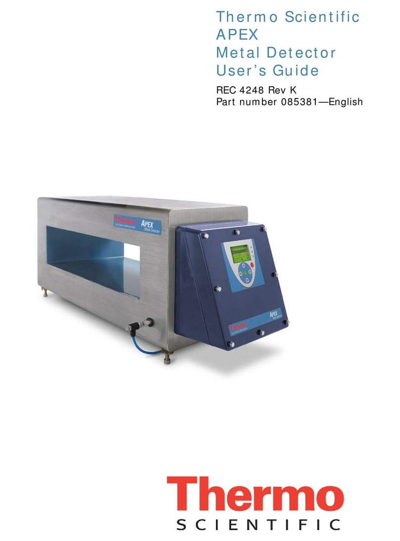
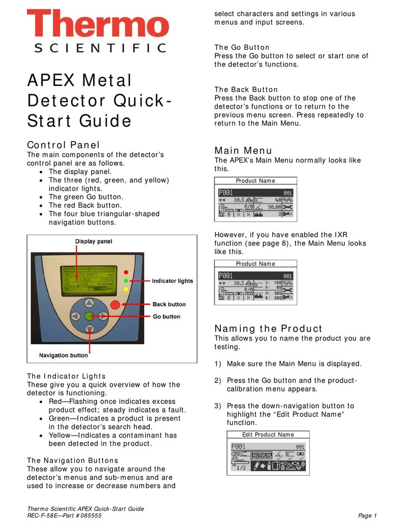
Thermo Scientific Apex User manual

Apex
Metal Detector
Service Guide
REC 4258 Rev C Part # 087929

Revision History
Revision Number Date Released ECO Number Release Specifics
Revision A March, 2007 1369 Official First Release
Revision B May 2007 1442 Added DSP3 to APEX upgrade
instructions, Chapter 11.
Revision C July 2007 1516 Added procedures to APEX software
upgrades.

©2006 Thermo Fisher Scientific. All rights reserved.
This document is confidential and is the property of Thermo Fisher Scientific (Thermo Scientific). It may not
be copied or reproduced in any way without the express written consent of Thermo Scientific. This document
also is an unpublished work of Thermo Scientific. Thermo Scientific intends to, and is maintaining the work as
confidential information. Thermo Scientific also may seek to protect this work as an unpublished copyright. In
the event of either inadvertent or deliberate publication, Thermo Scientific intends to enforce its rights to this
work under the copyright laws as a published work. Those having access to this work may not copy, use, or
disclose the information in this work unless expressly authorized by Thermo Scientific.
“Microsoft” and “Windows” are either registered trademarks or trademarks of Microsoft Corporation in the
United States and/or other countries.
All other trademarks are the property of Thermo Fisher Scientific and its subsidiaries.
Software Program License Terms
The Software Program is licensed, not sold. Thermo Fisher Scientific, grants you a license for the Software
Program only in the country where you acquired the Equipment, as defined below. You obtain no rights other
than those granted you under this license.
The term “Equipment” means the equipment with which the Software Program is used. The term “Software
Program” means the original and all whole or partial copies of the Software Program used in connection with
Equipment sold by Thermo Fisher Scientific to the user, including modified copies or portions of the Software
Program. Thermo Scientific retains title to the Software Program, as well as all improvements, modifications
and enhancements to the Software Program, whether made by Thermo Scientific or any other party. Thermo
Scientific owns, or has licensed from the owner, copyrights in the Software Program.
You are responsible for the selection of the Equipment.
Following the commissioning of the Equipment, any change made by the user to the Software Program will
terminate all warranties with respect to the Equipment and Software Program.
All other trademarks are the property of Thermo Fisher Scientific and its subsidiaries.
License
Under this license, you may:
1. Use the Software Program on only one piece of equipment at any one time, unless the license information
specifies otherwise;
2. Copy the Software Program for backup or in order to modify it;
3. Modify the Software Program and/or merge it into another Software Program; and
4. Subject to the following limitations, transfer the possession of the Software Program to another party, but
only in connection with a transfer of the Equipment.

If you transfer the Software Program, you must transfer a copy of these License Terms, all other
documentation and at least one complete, unaltered copy of the Software Program to the other party. Unless
you have other copies of the Software Program to be used in connection with other Equipment purchased
from Thermo Scientific , or one of its divisions, you must, at the same time, either transfer all your other
copies of the Software Program to the transferee of the Equipment or destroy them. Your license is then
terminated. The other party agrees to these terms and conditions by its first use of the Software Program.
You must reproduce the copyright notices(s) on each copy of the Software Program.
You may not:
1. Use, copy, modify, merge, or transfer copies of the Software Program except as provided in this license;
2. Reverse engineer, decompile, or disassemble the Software Program; or
3. Sub-license, rent, lease, or assign the Software Program.
Limitation of Remedies
Thermo Scientifics’ entire liability under this license is the following:
Thermo Scientific will: (a) replace defective media, or (b) make a warranted Software Program operate or (c)
replace the Software Program with a functionally equivalent Software Program, as warranted.
For any claim (including breach), in any form, related in any way to this license, Thermo Scientifics’ liability
will be for the actual value of the Software Program.
Thermo Scientific will not be liable for any lost profits, lost savings, any incidental damages, or other
economic consequential damages, even if Thermo Scientific, or its authorized supplier, has been advised of
the possibility of such damages. Thermo Scientific will not be liable for any damages claimed by you based on
any third party claim.
General
Thermo Scientific may terminate your license if you fail to comply with the terms and conditions of this
license. In such event, you must destroy all your copies of the Software Program. You are responsible for
payment of any taxes, including personal property taxes, resulting from this license.
Thermo Scientific Warranty
The seller agrees, represents, and warrants that the equipment delivered hereunder shall be free from defects
in material and workmanship. Such warranty shall not apply to accessories, parts, or material purchased by the
seller unless they are manufactured pursuant to seller's design, but shall apply to the workmanship
incorporated in the installation of such items in the complete equipment. To the extent, purchased parts or
accessories are covered by the manufacturer’s warranty; seller shall extend such warranty to buyer.
Seller's obligation under said warranty is conditioned upon the return of the defective equipment,
transportation charges prepaid, to the seller's factory in Minneapolis, Minnesota, and the submission of
reasonable proof to seller prior to return of the equipment that the defect is due to a matter embraced within
seller's warranty hereunder. Any such defect in material and workmanship shall be presented to seller as soon
as such alleged errors or defects are discovered by purchaser and seller is given opportunity to investigate and
correct alleged errors or defects and in all cases, buyer must have notified seller thereof within one (1) year
after delivery, or one (1) year after installation if the installation was accomplished by the seller.

Said warranty shall not apply if the equipment shall not have been operated and maintained in accordance
with seller's written instructions applicable to such equipment, or if such equipment shall have been repaired
or altered or modified without seller's approval; provided, however, that the foregoing limitation of warranty
insofar as it relates to repairs, alterations, or modifications, shall not be applicable to routine preventive and
corrective maintenance which normally occur in the operation of the equipment.
“EXCEPT FOR THOSE WARRANTIES SPECIFICALLY CONTAINED HEREIN, SELLER DISCLAIMS
ANY AND ALL WARRANTIES WITH RESPECT TO THE EQUIPMENT DELIVERED HEREUNDER,
INCLUDING THE IMPLIED WARRANTIES OF MERCHANTABILITY AND FITNESS FOR USE. THE
SOLE LIABILITY OF SELLER ARISING OUT OF THE WARRANTY CONTAINED HEREIN SHALL
BE EXCLUSIVELY LIMITED TO BREACH OF THOSE WARRANTIES. THE SOLE AND EXCLUSIVE
REMEDY FOR BREACH OF THE WARRANTIES SET OUT ABOVE SHALL BE LIMITED TO THE
REPAIR OR REPLACEMENT OF ANY DEFECTIVE ACCESSORY, PART OR MATERIAL WITH A
SIMILAR ITEM FREE FROM DEFECT, AND THE CORRECTION OF ANY DEFECT IN
WORKMANSHIP. IN NO EVENT SHALL SELLER BE LIABLE FOR ANY INCIDENTAL OR
CONSEQUENTIAL DAMAGES.”
Purchaser agrees to underwrite the cost of any labor required for replacement; including time, travel, and
living expenses of a Thermo Scientific Field Service Engineer at the closest factory base.
Thermo Fisher Scientific
501 90th Ave. NW
Minneapolis, MN 55433
Phone: (800) 227-8891
Fax: (763) 783-2525
Disclaimer
Though the information provided herein is believed to be accurate, be advised that the information contained
herein is not a guarantee for satisfactory results. Specifically, this information is neither a warranty nor
guarantee, expressed or implied, regarding performance, merchantability, fitness, or any other matter with
respect to the products, and recommendation for use of the product/process information in conflict with any
patent. Please note that Thermo Scientific reserves the right to change and/or improve the product design and
specifications without notice.

******
This page left blank intentionally
*********

Thermo Fisher Scientific Contents i
REC 4258 Rev C
Contents
Contents...................................................................................................................i
Figures.................................................................................................................... v
About this Manual..............................................................................................vii
Organization of this Guide....................................................................vii
Chapter 1 .............................................................................................................1-1
Search Head PCBA Head Setup .....................................................................1-1
APEX Frequency Limitations.............................................................. 1-1
Safety .................................................................................................. 1-1
Search Head PCB................................................................................ 1-2
Oscillator Transformer Ratio ........................................................... 1-2
Oscillator Frequency ........................................................................ 1-3
Oscillator Amplitude........................................................................ 1-4
Input Tuning ................................................................................... 1-5
Electronic Balance............................................................................ 1-7
Search Head Screen........................................................................... 1-11
Auto Balance..................................................................................... 1-11
Search Head PCP Layout.................................................................. 1-13
Fine Tuning the System .................................................................... 1-14
Parts Required................................................................................ 1-14
Chapter 2 .............................................................................................................2-1
APEX I/O and PSU Connections......................................................................2-1
Wiring AC Power into the PSU PCBA ............................................ 2-2
Input Power Consumption .............................................................. 2-2
Wiring Outputs from the PSU PCBA (Not recommended)............ 2-2
Wiring Inputs into the PSU PCBA .................................................. 2-3
Inputs .............................................................................................. 2-4
Overview of connections on Relay PCBA............................................ 2-4
Relay outputs ...................................................................................... 2-5
Communication Output ..................................................................... 2-5

Contents
ii Contents Thermo Fisher Scientific
REC 4258 Rev C
Chapter 3 .............................................................................................................3-1
Control Panel Assembly...................................................................................3-1
How Too Upgrade the APEX Software............................................... 3-1
PN 090896 - APEX CPU Programming Cable – C07387M-E007.. 3-1
Upgrade Method 1 – MS-DOS boot floppy .................................... 3-2
Upgrade Method 2 – Upgrading in Windows.................................. 3-3
APEX error codes................................................................................ 3-5
Enable Passwords ................................................................................ 3-7
Assigning/Changing Passwords ........................................................ 3-8
Setup................................................................................................... 3-9
Chapter 4 .............................................................................................................4-1
Maintenance and Troubleshooting ...............................................................4-1
Cleaning.............................................................................................. 4-1
Check for Corrosion ........................................................................ 4-2
Fault Finding ...................................................................................... 4-2
Search Head Faults........................................................................... 4-2
Reject Confirm Fault ....................................................................... 4-2
Battery Low Fault............................................................................. 4-3
Product Memory Fault..................................................................... 4-3
Photo Reject Fault – Conveyor Systems ........................................... 4-3
Shaft Encoder Fault – Conveyor Systems ......................................... 4-3
QA Test Response Fault................................................................... 4-3
QA Test Result Fault ....................................................................... 4-4
Excess Reject Fault ........................................................................... 4-4
Phase Limit Fault ............................................................................. 4-4
Photo-eye Block Fault ...................................................................... 4-4
AuditCheck Fault............................................................................. 4-5
Recommended Testing Procedures................................................... 4-5
Testing Schedule .............................................................................. 4-6
Record Keeping................................................................................ 4-7
Rejected Product Examination ......................................................... 4-7
QA Test Request.............................................................................. 4-7
Service Repair and Replacement Parts ................................................. 4-7
Parts Ordering Information............................................................ 4-11
Parts............................................................................................... 4-12
Phone/Fax Contacts for
Thermo Scientific
Offices......................... 4-13
Battery Replacement ........................................................................ 4-1
Disposal of Hazardous Waste........................................................... 4-2

Contents
Thermo Fisher Scientific Contents iii
REC 4258 Rev C
Chapter 5 .............................................................................................................5-1
Part & Drawing Numbers ................................................................................5-1
Printed Circuit Board Assemblies........................................................ 5-1
Control Panel Assemblies .................................................................... 5-1
Cable Assemblies................................................................................. 5-2
Chapter 6 .............................................................................................................6-1
Reference Material...........................................................................................6-1
DSP3/APEX Differences..................................................................... 6-1
DSP3 Sensitivity Control VS APEX Detection Level Control.......... 6-1
DSP3 PCNR VS APEX PNR .......................................................... 6-1
Loss of DSP3 VNX.......................................................................... 6-2
APEX DSV Filter............................................................................. 6-2
APEX DAG Method........................................................................ 6-3
APEX Display Size ........................................................................... 6-3
Plastic Control Box – Will it Shield RF? .......................................... 6-3
Aperture Size Programming on CPU ............................................... 6-4
APEX BNC Connector.................................................................... 6-4
APEX Quick Start Documentation ..................................................... 6-4
Product Speed and Filtering the Signal............................................. 6-5
Rejecting the Product....................................................................... 6-5
Reject Duration................................................................................ 6-5
Rejecting the Product More Accurately ............................................ 6-6
Packs that are to close to each other ................................................. 6-6
Failsafe Operation ............................................................................ 6-6
Recapping so far............................................................................... 6-6
Product Effect .................................................................................. 6-7
Wet and Dry Product....................................................................... 6-7
Phase Tracking................................................................................. 6-7
Recap +1 .......................................................................................... 6-8
Detection Level ................................................................................ 6-8
Effects of Vibration and Mechanical Shock...................................... 6-9
Metal Free zone................................................................................ 6-9
APEX signal Improvement Algorithms.............................................. 6-10
QNR.............................................................................................. 6-10
PNR............................................................................................... 6-10
CLX............................................................................................... 6-10
Phase Tracking............................................................................... 6-11
Balance Correction Switch Settings on Search Head PCB ................. 6-12
To recap, SW1 effectiveness is due to: -.......................................... 6-12

Contents
iv Contents Thermo Fisher Scientific
REC 4258 Rev C
Chapter 7 .............................................................................................................7-1
AuditCheck™......................................................................................................7-1
Theory of Operation ........................................................................... 7-1
Operation ........................................................................................... 7-3
Setup – Speed Shuttle Calibration.................................................... 7-3
Software Setup ................................................................................. 7-4
Manual AuditCheck Test................................................................. 7-7
Faults and Alarms............................................................................. 7-7
AuditCheck Patented Sensitivity Test System ..................................... 7-8
AUDITCHECK THEORY OF OPERATION ............................ 7-11
SUMMARY................................................................................... 7-17
Chapter 8 .............................................................................................................8-1
Using the APEX Oscilloscope.........................................................................8-1
Chapter 9 .............................................................................................................9-1
Cold Start.............................................................................................................9-1
Chapter 10 .........................................................................................................10-1
Oscillator...........................................................................................................10-1
Chapter 11 .........................................................................................................11-1
DSP3 to APEX Upgrade Instructions............................................................11-1
DSP3 Parts...................................................................................... 11-18
Chapter 12 .........................................................................................................12-1
APEX Software Update...................................................................................12-1
Upgrade Method 1 – MS-DOS Boot Floppy .................................... 12-2
Upgrade Method 2 – Upgrading in Windows................................... 12-3
Troubleshooting................................................................................ 12-6
Update not Starting........................................................................ 12-6
Transfers Timing Out .................................................................... 12-6
Chapter 13 .........................................................................................................13-1
Engineering Drawings....................................................................................13-1

Contents
Thermo Fisher Scientific Contents v
REC 4258 Rev C
Figures
Figure 1–1. Oscillator Transformer Ratio .....................................................1-2
Figure 1–2. Oscillator Amplitude....................................................................1-4
Figure 1–3. 90 degree input phase shift ........................................................1-5
Figure 1–4. Input Tuning...................................................................................1-6
Figure 1–5. Electronic Balance Correction (HF)..........................................1-8
Figure 1–6. Electronic Balance Correction (LF) ........................................1-10
Figure 1–7. Auto Balance...............................................................................1-12
Figure 1–8. Search Head PCB Layout ..........................................................1-13
Figure 2–1. PSU PCBA connections...............................................................2-1
Figure 3–1. Password Screen 1 ......................................................................3-7
Figure 3–2. Password Entry Screen...............................................................3-7
Figure 3–3. Password Screen 2 – Assigning Passwords (Level 3 access
only.......................................................................................................................3-8
Figure 3–4. Password Entry Screen...............................................................3-8
Figure 3–5. Password Confirmation Screen ................................................3-9
Figure 7–1. Cross section of the search head on a conveyor system.....7-2
Figure 7–2. AuditCheck Screen 1 ...................................................................7-4
Figure 7–3. AuditCheck Screen 3 ...................................................................7-6
Figure 7–4. Head Sensitivity............................................................................7-9
Figure 7–5. AuditCheck Sensitivity..............................................................7-12
Figure 7–6. AuditCheck Elements ................................................................7-14
Figure 7–7. Amplitude of the Signal.............................................................7-15
Figure 11–1. Integral Conversion Kit............................................................11-2
Figure 11–2. Integral Conversion Kit Front View.......................................11-2
Figure 11–3. Integral Conversion Kit Back View ......................................11-3
Figure 11–4. DSP3 Unit to be Upgraded ......................................................11-3
Figure 12–1. APEX CPU Programming Cable .............................................12-1

Contents
vi Contents Thermo Fisher Scientific
REC 4258 Rev C
******
This page left blank intentionally
*********

Thermo Fisher Scientific About this Manual vii
REC 4258 Rev C
About this Manual
The APEX Service Guide is a learning resource and reference for use by
Thermo Scientific Service Engineers and those adequately trained by
Thermo Scientific to perform installation, customer training, product
commissioning, and parts replacement.
It is an introduction to the product and a theoretical outline for the
instrument and its operation.
Full Service
Repair Install Maintenance Troubleshooting
Service
People
3333
Distributor 3333
Trained
Customer
X X 33
This guide is organized into 12 chapters. Other good resource for APEX
operations are REC 4248, APEX Metal Detector User Guide and REC-
58 Quick Start Guide that can be obtained by contacting Thermo
Scientific .
Chapter 1: Search Head PCBA Head Setup
Chapter 2: APEX I/O and PSU Connections
Chapter 3: Control Panel Assembly
Chapter 4: Maintenance and Troubleshooting
Chapter 5: Part & Drawing Numbers
Chapter 6: Reference Material
Chapter 7: AuditCheck™(Not Available on APEX 100)
Chapter 8: Using the APEX Oscilloscope
Chapter 9: Cold Start
Chapter 10: Oscillator
Chapter 11: DSP3 to APEX Upgrade Instructions
Chapter 12: Engineering Drawings
Organization
of this Guide

About this Manual
viii About this Manual Thermo Fisher Scientific
REC 4258 Rev C
Instructions in this manual may require special precautions to ensure the
safety of the personnel performing the operations.
Please read the safety information before performing any operation.
There are two levels of safety messages: warnings and cautions. The
distinction between the two is as follows:
WARNING. Failure to follow safe installation and servicing procedures
could result in death or serious injury. ▲
CAUTION. Failure to observe may cause minor injury or damage to
equipment. ▲
Do not install, operate, or perform any maintenance procedures until you
have read the safety precautions presented.
WARNING. Failure to follow safe installation and servicing procedures
could result in death or serious injury.▲
Make sure only qualified personnel perform installation and maintenance
procedures in accordance with the instruction in this manual.
Allow only qualified electricians to open and work in the electronics
cabinets, power supply cabinet, control cabinet, or switch boxes.
Covers over the electronics and rotating parts must always remain in
place during normal operation. Remove only for maintenance, with the
machine’s power OFF. Replace all covers before resuming operation.
During maintenance, a safety tag (not supplied by the factory) to be
displayed in the ON/OFF switch areas instructing others not to operate
the unit (ANSI:B157.1).
Safety
Messages
General
Precautions

About this Manual
Thermo Fisher Scientific About this Manual ix
REC 4258 Rev C
WARNING. High voltage that may be present on leads could cause
electrical shock. ▲
All switches must be OFF when checking input AC electrical
connections, removing or inserting printed circuit boards, or attaching
voltmeters to the system.
Use extreme caution when testing in, on, or around the electronics
cabinet, PC boards, or modules. There are voltages in excess of 115 V or
230 V in these areas.
WARNING. Use only the procedures and new parts specifically
referenced in this manual to ensure specification performance and
certification compliance. Unauthorized procedures or parts can render
the instrument dangerous to life, limb, or property.▲
WARNING. Keep hands and clothing away from all moving or rotating
parts. ▲
WARNING. Do not place or store objects of any kind on the machine. ▲
WARNING. This machine should not be operated at more than the
production rate stated on your Equipment Specification sheet, used in
applications other than those stated in the original order, or in a manner
not specified by
Thermo Scientific
. To do so may impair the protection
provided by the machine. ▲

About this Manual
xAbout this Manual Thermo Fisher Scientific
REC 4258 Rev C
******
This page left blank intentionally
*********

Thermo Fisher Scientific Search Head PCBA Head Setup 1-1
REC 4258 Rev C
Chapter 1
Search Head PCBA Head Setup
High frequency operating range: 100 kHz – 500 kHz[g1]
Low frequency operating range: 30 kHz – 150 kHz
Minimum frequency ratio 2:1
Maximum frequency ratio 4:1
Pharmaceutical detector: Single frequency only - 700 kHz
Note. While it is possible to set the APEX to any operating
frequency in the ranges listed above, there is the following
operating frequency limitations on all integral heads due to the
switching PSU (132Khz switching frequency) mounted in close
proximity to the search head. Remote mount heads are not
affected ▲
DO NOT SET OPERATING FREQUENCY ON INTEGRAL
HEADS WITH IN THE FOLLOWING RANGES.
132Khz (+/- 10Khz)
264Khz (+/- 10Khz)
396Khz (+/- 10Khz)
Note. Search head aperture size acts as a restriction to operating
frequency; it may not be possible to achieve the lowest frequencies on
some smaller heads. ▲
APEX power supply has been designed to produce safe voltage
outputs under single fault conditions, which means the search head,
can be tested without special procedures. Testing when the Power
Supply is fed from AC voltages should only be done by trained
personnel.
APEX
Frequency
Limitations
Safety

Search Head PCBA Head Setup
1-2 Search Head PCBA Head Setup Thermo Fisher Scientific
REC 4258 Rev C
Before fitting replacement PCB, check the position of solder jumper
JP14. Change position if necessary (solder link from bottom of PCB).
Position to suit high/low frequency option.
A96843
Figure 1–1. Oscillator Transformer Ratio
Table 1–1. JP14 Frequency Options
Solder Link (2+3)
Ratio 2:1 Solder Link (1+2)
Ratio 4:1
500kHz/150kHz 500kHz/50kHz
500kHz/100kHz 300kHz/50kHz
300kHz/150kHz 200kHz/50kHz
300kHz/100kHz
200kHz/100kHz
150kHz/50kHz
100kHz/50kHz
Search Head
PCB
Oscillato
r
Transforme
r
Ratio
JP14 3 JP14 1 3
Earth Strap JP1
JP14Screen

Search Head PCBA Head Setup
Thermo Fisher Scientific Search Head PCBA Head Setup 1-3
REC 4258 Rev C
1. Remove the search head screen and fit PCBA, rotate the top of
Nylatch to secure.
2. Solder Oscillator and input coil connections, ensure the solder
flows fully around the joint.
3. Fasten the earth strap to the body of the head.
4. Refit the search head screen.
This section outlines the steps to set the oscillator frequency
1. Remove the search head screen.
2. Connect 24Vdc power supply to connector block. (Positive to
JP1_12 and negative to JP1_11) (Refer to Figure 1 or Figure 2,
this step is for manufacturing ONLY).
3. Solder nominal capacitance value across CL1-CL10 (120nF) and
CH1-CH10 (120nF).
4. Connect scope earth to earth point, monitor tp122 [Oscillator o/p].
5. Set JP6 [frequency select] to high frequency operation.
6. Adjust VR3 [amplitude control] for minimum (fully clockwise).
7. Set JP7 [FET current] to low.
8. Turn power on and check oscillation begins.
9. Add tuning capacitors across CH1-CH10 to set high frequency
+/- 5kHz (1200nF max).
10. Set JP6 [frequency select] to Low Frequency operation.
11. Add tuning capacitors across CL1-CL10 to set low frequency
+/- 3kHz (600nF max).
Oscillato
r
Frequency
1
1
1

Search Head PCBA Head Setup
1-4 Search Head PCBA Head Setup Thermo Fisher Scientific
REC 4258 Rev C
This section outlines the steps to set the oscillator amplitude.
1. Set JP6 [frequency select] to high frequency operation.
2. Adjust VR3 [amplitude control] to voltage indicated by graph (see
Chapter 2), if this cannot be achieved set to max un-distorted (do
not exceed 40V).
3. Tolerance: 100-150 kHz = +/- 2V, 200-500 kHz = +/- 4V.
4. If signal becomes unstable during adjustment, set JP7 [FET
current] to medium.
5. If instability persists, set JP7 [FET current] to High.
6. Set JP6 [frequency select] to Low frequency operation.
7. Check signal is clean sine wave, if distortion is visible adjust VR3
[amplitude control] to max amplitude with no distortion. If signal
is unstable, increase current using JP7 (FET current). Compare to
voltage indicated by graph (see Chapter 2), if this cannot be
achieved check solder jumper JP14. Tolerance: 50 kHz = +/- 2V,
100-150 kHz = +/- 3V.
8. Reduce power supply to 22Vdc. Check oscillator remains stable at
both frequencies (CAUTION. For manufacturing purposes
ONLY).
A96843 Figure 1–2. Oscillator Amplitude
Oscillato
r
Amplitude 1
1
1
1
JP7
FET
curren
t
JP1 JP6
(frequency
select)
Search
Head
CL1 – CL10
(low frequency)
VR3
(amplitud
e control
)
TP122
(oscillator o/p)
CH1 – CH10
(high
frequency)
Other manuals for Apex
1
Table of contents
Other Thermo Scientific Metal Detector manuals

Thermo Scientific
Thermo Scientific APEX 500 Rx User manual

Thermo Scientific
Thermo Scientific Apex User manual

Thermo Scientific
Thermo Scientific Ramsey Oretronic IV User manual

Thermo Scientific
Thermo Scientific DSP2 Owner's manual

Thermo Scientific
Thermo Scientific Oretronic III Instruction and safety manual

Thermo Scientific
Thermo Scientific APEX 100 User manual