WARNING
PLEASE READ INSTRUCTION BEFORE COMMENCING INSTALLATION AND RETAIN FOR FUTURE REFERENCES.
Electrical products can cause death or injury, or damage to property.
If in any doubt about the installation or use of this product, consult a competent electrician.
INSTALLATION GUIDE
WARNING — THE INSTALLATION MUST BE CARRIED OUT BY
A QUALIFIED ELECTRICIAN.
1. DO NOT let power cords touch hot surfaces
2. DO NOT install near gas or electric heaters
3. DO NOT use this LED Emergency Light other than its intended purpose
4. LED Emergency Lights can only be installed by a qualified electrician
5. This LED Emergency Light is for indoor use ONLY
Instruction Manual
1-888-543-6473
1-888-541-6474
13376 Comber Way
Surrey BC V3W 5V9
www.ortechindustries.com
375 Admiral Blvd
Mississauga, ON L5T 2N1
CAUTION
Application Notice
TO REDUCE THE RISK OF FIRE, ELECTRIC SHOCK, OR INJURY TO PERSONS, READ THE INSTRUCTIONS BELOW:
1. Use caution when servicing batteries. Battery acid can cause burns to skin and eyes.
If acid is spilled on skin or eyes, flush acid with fresh water and contact a physician immediately
2. LED Emergency Lights should be mounted in locations and at heights where unauthorized personnel will not readily subject it to tampering
3. The use of accessory equipment not recommended by manufacturer may cause an unsafe condition, and will void the unit's warranty
4. DO NOT use this LED Emergency Light for other than its intended purpose
5. Failure to insulate unused wire may result in shock hazard or unsafe condition as well as equipment failure
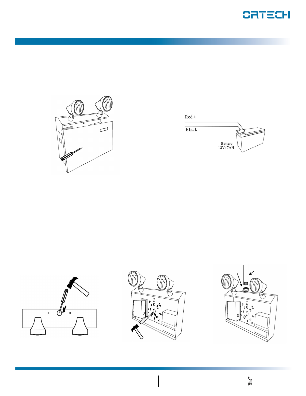
Hardwire Installation
1. Extend un-switched 20 hour AC supply of rated voltage to a junction box (supplied by others) installed in
accordance with all applicable codes and standards. Leave a minimum of 8 inches of slack on the wire. This
circuit should NOT be energized / live at this time
2. Open the unit by unscrewing the cover screws on the sides of the unit. The front cover can then be removed
3. Unit is supplied with universal spider knockouts and keyhole slots stamped into the back of the cabinet.
Knock out of the appropriate hole(s) and bring wires through the hole(s) into the cabinet
4. Mount the unit securely into place. DO NOT rely on the electrical box as the only support for the unit
5. Make proper wiring connections between the AC supply and the unit's transformer:
Black-Line:120V AC; Red-Line 347V AC; Green-Line Earth (see Wiring Diagram below)
Wiring Diagram
AC Wiring
Working voltage: 120V-347V AC/ 50-60Hz
Black Wire: 120V AC (L1)
Red Wire: 347V AC (L2)
White Wire: (N)
Green Wire: (G/E)
LED Emergency Lights
MODEL OE-216-72W