Osculati 13.226.12 Installation instructions

Installation & Operation Instructions
Deluxe LED Spot Light
Model 13.226.12/13.226.24
To avoid the risk of accidents or
damage to this product, it is essential
to read these instructions thoroughly EN Edition
before this product is installed and used. Sep 2020

1
Contents
Product Highlights ................................................................................................... 2
Specifications ........................................................................................................... 2
Installation ................................................................................................................. 2
Spot Light Installation .......................................................................................... 2
Joystick Control Panel Installation ....................................................................... 3
Remote Control Bracket Installation .................................................................... 4
Mounted Remote Control Installation (allows multiple controls for one light) ....... 4
Electrical Wiring ................................................................................................... 5
Operation ................................................................................................................... 6
Joystick Control ................................................................................................... 6
Remote Control ................................................................................................... 7
Caution ...................................................................................................................... 7
Maintenance .............................................................................................................. 8
Troubleshooting ....................................................................................................... 9
Limited Warranty .................................................................................................... 10

2
Product Highlights
Certified in compliance with IEC 60598-2-5:1998 (safety), EN 55015 + EN 61547 (CE), EN
301 489-1/-3 + EN 300 440-2 (RF), FCC Part 15B/15C (FCC), EN 60945 (marine), IP67.
Powered by latest LED technology.
Brighter than 100 Watts halogen bulb, power usage as low as 54 Watts.
355° two speed horizontal rotation, 50° vertical range.
Can use multiple remote controls and add a joystick control panel.
Digital remote control signal reliable and resistant to interference.
Uses telephone line. Simple connection compared to traditional wire harness.
Aluminum body with corrosion-resistant coating.
Completely sealed and waterproof.
12 Volts DC input power. (24 Volts DC input power for 13.226.24)
Specifications
Material Aluminum body, glass front cover
Styling Streamline
Light Source High power LED (18 LED @ 54 Watts), over-heating protection
Light Coverage 0.25 Lux @ 726 m, triple spot diameter vs. 100W Halogen light bulb
Light Mode Spot light
Rotation 355° horizontal (dual speed), 50° vertical, jam protection
Power Cable 5 ft
Power Supply 12 VDC (24V DC for 13.226.24)
Size L x W x H 21 x 20 x 25 (cm)
Weight 5.5 kg
Current Draw 5 Amp (2.5 Amp for 13.226.24)
Installation
Spot Light Installation
1. The spot light should be installed on flat, level, and non-metal surface.
2. Make use of the foam gasket to mark mounting holes and wiring access (1 inch or 25.4 mm) on
flat surface, see picture below. Make wiring access.
3. Route the power cable and signal lines through wiring access of the gasket and flat surface.
4. Secure deck mount by four (4) self-tapping screws of 1/4 inch (6 mm), or bolts and nuts.
! Remember to install the foam gasket, and ensure proper sealing.
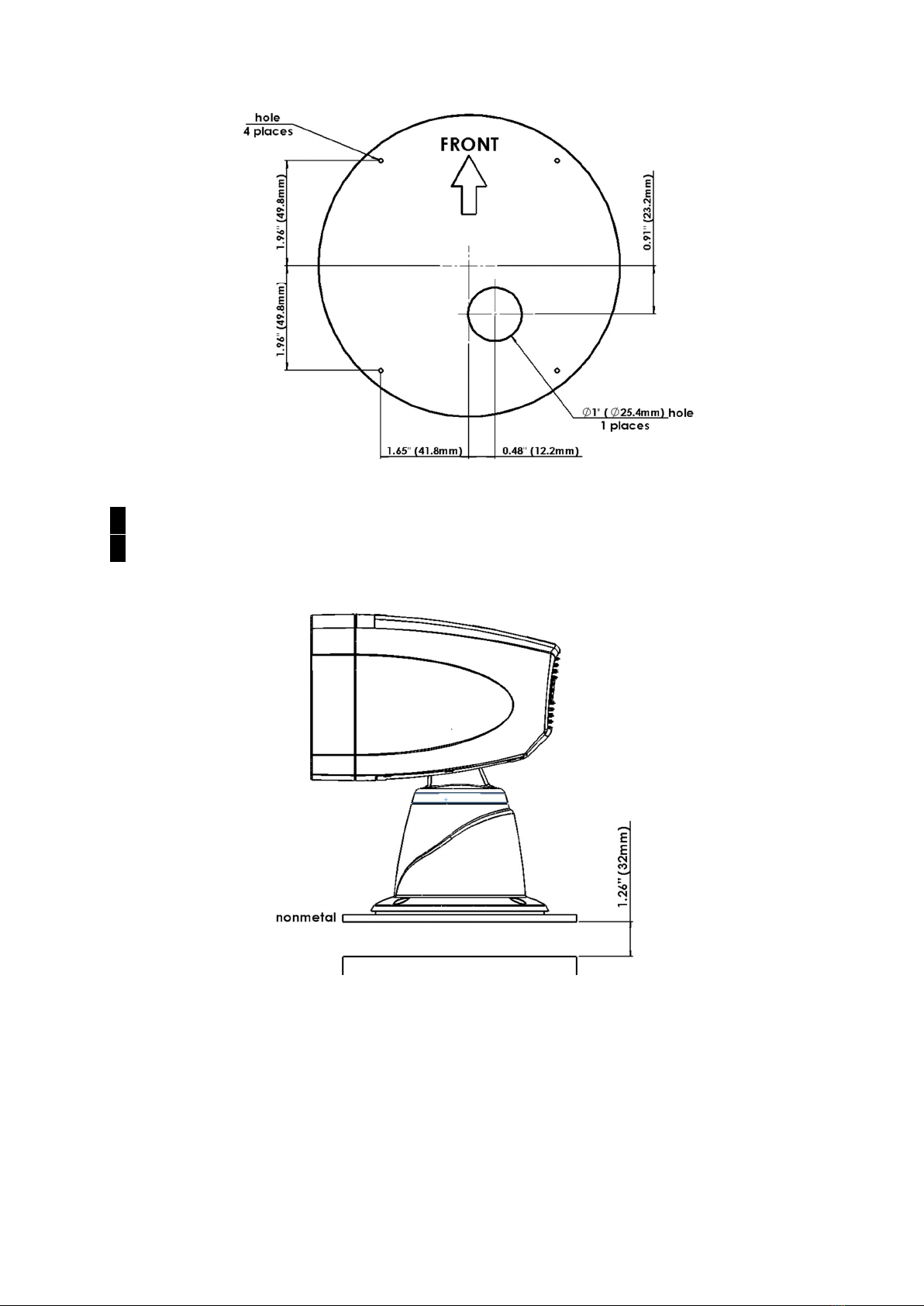
3
! Do not mount on metal surface; remote control will not work.
! Provide at least 1-1/4 inch (32 mm) clearance underneath the mounting surface to allow reception
of remote signal. Remote control may not work if clearance is insufficient.
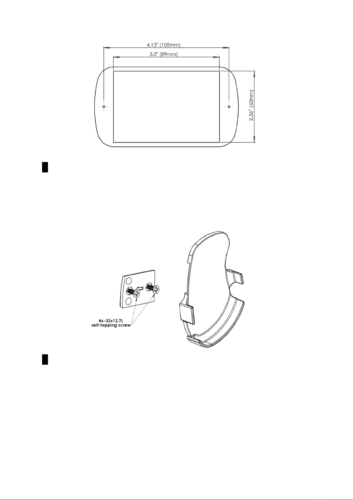
Joystick Control Panel Installation
1. The joystick control panel should be installed on flat surface at a dry location.
2. Make use of the foam gasket to mark mounting holes and rectangular hole (3-1/2 by 2-3/ 8 inch or
89 by 60 mm) on flat surface. Make rectangular hole.
3. Take off top cover from joystick control panel, then fit control panel into the rectangular hole.
Secure control panel with two (2) #8 (M4) self-tapping screws or bolts and nuts.
4. Put back top cover.
4
! Provide water and weather protection for the location where joystick control panel is installed.
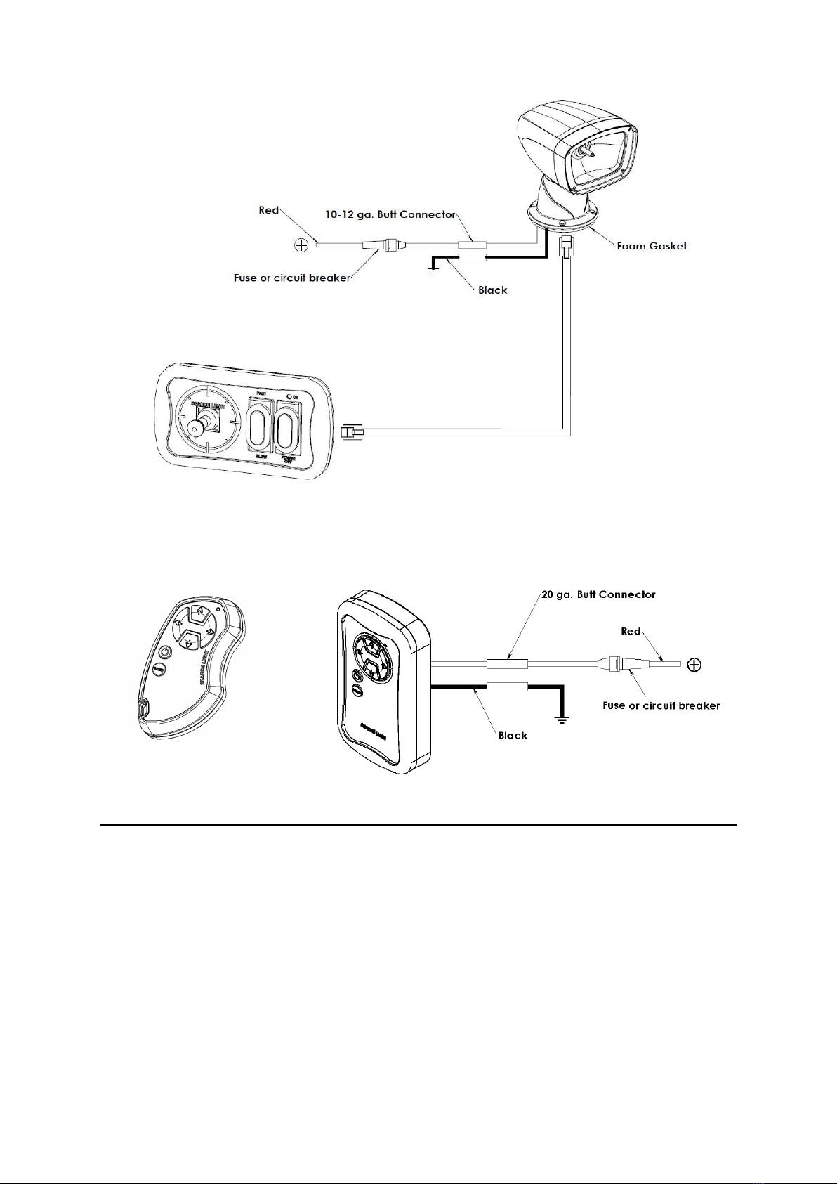
Remote Control Bracket Installation
1. Take off mounting plate from the back of bracket. Secure mounting plate on selected location
with the two (2) self-tapping screws that come with the product.
2. Fit bracket to mounting plate as shown in below.
! Provide water and weather protection for the location where remote control bracket is installed.
Mounted Remote Control Installation (allows multiple controls for one light)
1. The mounted remote control should be installed on flat surface at a dry location.
2. Make wiring access of size 5/8 inch or 16 mm.
3. Remove the front cover then route the power cable through wiring access.
4. Secure mounted remote control by two (2) M4 self-tapping screws. Put back the front cover.

5
Electrical Wiring
1. Provide DC 12 Volt input power for 13.226.12. (Provide DC 24 Volt input power for 13.226.24)
2. Protect input power positive (+) terminal with 8 A fuse or circuit breaker. (Use 4 A fuse for
13.226.24)
3. Use 12-gauge power cable for wiring distance not more than 30 ft (9 m), and use 10-gauge power
cable for longer wiring distance.
4. According to your control device, see below and the diagram:
(a) If joystick, the spot light links to joystick control panel by telephone line.
(b) If handheld remote control, no additional wiring needed.
(c) If mounted remote control, provide input power to the mounted remote control. Protect
input power positive (+) terminal with 1 A fuse or circuit breaker.
! The power switch on joystick control panel should be set to “POWER OFF” before supplying power
to the product.
! Use correct product for your power source (DC 12 or 24 Volt). Wrong voltage will damage product
and may cause safety hazard.
6
Operation
Joystick Control
1. The control of spot light by joystick is straightforward.
2. The speed switch (see picture below) is for horizontal rotation only.
( c )
( b )
( a )

7
Remote Control
1. Press arrow key to control rotation of the spot light.
2. The speed switch (see picture below) is for horizontal rotation only.
3. Same operation for mounted remote control.
Caution
! Model 13.226.12 and 13.226.24 have over-heating protection. Upon activation of over-heating
protection, the product will turn off 6, 12, or all LED. The product will resume normal operation
after 30 to 60 minutes typically. Continuous operation for more than two (2) hours should be
avoided.
! DO NOT try to operate the product beyond angular range as it will damage the product.
! DO NOT press or hit the glass front cover.
! DO NOT look directly into the spot light while the product is in operation.
! DO NOT cover the light with any material, otherwise accidental activation of the product may result
in fires.
8
Maintenance
How to conduct general care …
1. Use diluted neutral cleanser for general cleaning.
! Do not use other chemicals or abrasives.
2. No need to provide additional lubrication.
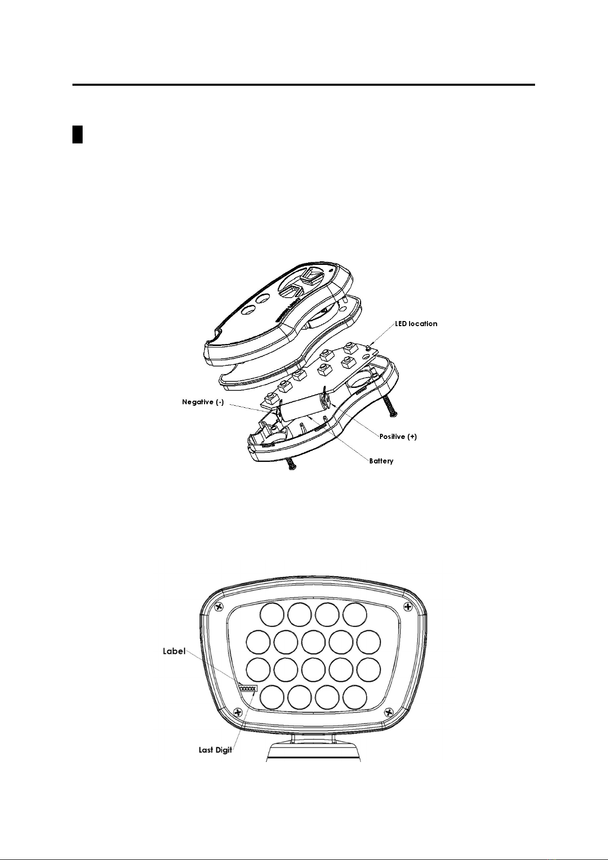
How to replace battery for remote control …
1. Remove remote control from bracket.
2. Loosen the two (2) screws from back cover of remote control.
3. Carefully dissemble remote control, see details in picture below.
4. Replace the used 12V / A23 battery with new one.
5. Push any button to check if the LED indicator illuminate.
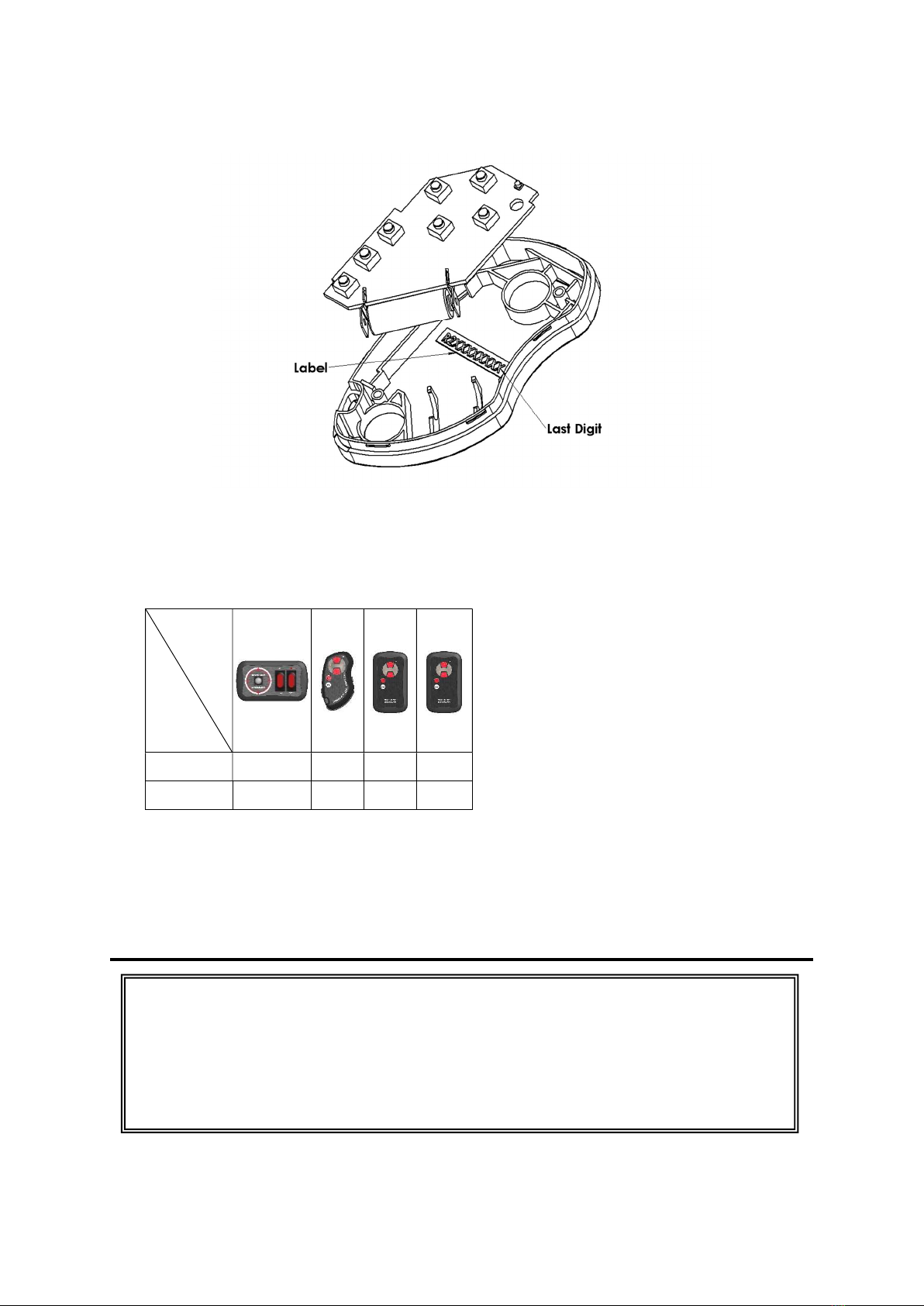
How to replace or add remote controls …
Locate serial number in one of the following locations:
1. In case of remote control missing, user can remove the four (4) screws and take off glass front
cover to obtain serial number shown on the label placed inside housing, see picture below. Note
the last digit of the serial number L2XXXXXXXX (X=0~9) then notify dealer.
9
2. User can also loosen the two (2) screws from back cover of the remote control to obtain serial
number shown on label R2XXXXXXXX (X=0~9). Note the last digit of serial number then notify
dealer.
Which are replaceable parts …
1. LED light assembly
2. LED driver
3. Controls:
Control
Light
Model
Joystick
13.226.39
Remote
13.226.40
Mounted
Remote
13.226.41
Mounted
Remote
13.226.42
13.226.12 V V V
13.226.24 V V V
4. Main PC board
5. Lower motor
6. Upper motor
7. Digital cable (RJ11 6P4C Pin 1-1 straight through, 15 ft / 25 ft / 35 ft) for 13.226.39.
Troubleshooting
Installation work and repairs to electrical components of this product must
only be carried out by a suitably qualified and competent person in
accordance with current local and national safety regulations. Repairs
and other work by unqualified persons could be dangerous. The
manufacturer cannot be held liable for unauthorized work.

10
What to do if …
… the LED does not light.
The light may be turned off by over-heating protection. Turn off power to allow the light to cool
down. The light will resume normal operation after 30 to 60 minutes typically.
Examine the LED light assembly.
Check if correct type of telephone line (RJ11 6P4C Pin 1-1 straight through) is used.
… the spot light does not respond to remote control.
Press and hold button for 2 seconds.
Move to a location that is less than 15 m away.
Move to a location that has no obstructing structure between remote control and spot light.
Make sure the light is not mounted on any metal surface and there is sufficient clearance below.
Replace battery for remote control.
Check whether the last digits of serial numbers inside light housing and inside remote control are
identical.
… the spot light does not respond to any control.
Check voltage of inboard battery.
Check the fuse or circuit breaker that protects spot light and joystick control panel.
Carefully uninstall the spot light. Examine the electrical connections and wire harness.
Check if correct type of telephone line (RJ11 6P4C Pin 1-1 straight through) is used.
! Do not replace a blown fuse until the cause of spot light malfunction is identified and resolved.
! DO NOT replace a blown fuse with a fuse that takes higher current.
… the spot light halt during operation.
Return spot light and joystick control panel to dealer for further inspection.
… the spot light cannot rotate in certain direction.
Carefully uninstall the spot light and examine the electrical connections and wire harness.
Replace joystick control panel.
For other problems, and when problem is not solved with the above tips …
Return complete product with proper packaging to dealer for inspection. Include a description of the
problem, user contact information, and proof of purchase if requesting warranty service.
Limited Warranty
For one (1) year from the date of original purchase, Osculati will, at its discretion, repair or replace for
the original consumer, free of charge, any parts found defective in material or workmanship. All
transportation charges under this warranty must be borne by the consumer.
Proof of purchase is required: A computerized register receipt is required. Hand-written receipts are
not accepted for warranty proof of purchase. In the absence of a receipt, warranty period will be
calculated from date of manufacture printed or stamped on the product.
There is no other expressed warranty. Implied warranties, including those of merchantability and
fitness for a particular purpose, are limited to one (1) year from the date of purchase. This is the
exclusive remedy and consequential damages are excluded where permitted by law.
This warranty does not apply if the product has been damaged by accident or misuse, or as a result of
service or modification performed by an unauthorized factory. Except as otherwise expressly stated
in the previous paragraph, the company makes no representation or warranty of any kind, express or
implied, as to merchantability, fitness for a particular purpose, or any other matter with respect to this
product. The company shall not be liable for any consequential loss to life safety and property if it’s
due to user’s failure in following this manual to install and use the product.
Changes or modifications not expressly approved by the party responsible for compliance
could void the user's authority to operate the equipment.

Osculati s.r.l.
Via Pacinotti, 12
20090 Segrate (MI) - Italy
Tel: +39 02 2699 111
Fax: +39 02 2699 1120
www.osculati.it
Distributor
All rights reserved / EN-Sep-2020
This manual suits for next models
1
Table of contents
Popular Spotlight manuals by other brands

Havis-Shields
Havis-Shields CD-RH-HID35W owner's manual

Chauvet
Chauvet Intimidator Spot LED 250 user manual

NEBO
NEBO NEB-LSP-0006 Use and care guide

Good Earth Lighting
Good Earth Lighting SE1303-WH3-00LFW-G manual

High End Systems
High End Systems SolaSpot Pro 1500 user manual

Schego
Schego schegoLUX-max operating instructions


West Marine
West Marine 17335076 owner's manual

Princeton Tec
Princeton Tec SECTOR 5 Operating and maintenance instructions

EuroLite
EuroLite LED SLS-12 HCL 12x8W user manual

Robus
Robus RFN00560I20-01 instruction manual

Vision & Control
Vision & Control SLB-500-W5K7-P-SL Instructions for use

ADJ
ADJ Mystic Led User instructions