Osram ams AS7050 User manual

2
AS7050 Evaluation Kit Quick Start Guide
Contents
AS7050 EVK
Install Software
How to Use
AS7050 PC Software
Logging Data
FW Upgrade

3
Contents of the AS7050 Evaluation kit
AS7050 Evaluation kit parts
Out of the Box
•1–AS7050 EVK Mainboard
•2–SMOD board SFH7072 with Optical stack
•3–SMOD board SFH7074 with Optical stack
•4–Micro USB cable
•5–FPC Cable
•6–Generic Bluetooth Board
Fig. 1: AS7050 Evaluation Kit out of the box
1
23
4
5
6

4
Contents of the AS7050 Evaluation kit
Evaluation kits main parts
Fig. 2: AS7050 Evaluation Kit top view
•Key
•1- OSRAM SFH 7072 LED/PD
module
•2- AS7050 Sensor
•3- Three ECG Electrodes
•4- Bluetooth Microcontroller
module and USB connector
•5- Battery Connection
•6–sensor board on/off switch
•Note:
1. It is recommended to unplug the
battery connection when the EVK is
turned off.
2. For independent functions, use the
battery e.g. Bluetooth connection
1
2
5
4 6 3

6
Setup
Getting Started
Fig. 4: AS7050 Evaluation Kit power ON
1. Optionally, connect electrodes to the connector on the back of
the external electrodes.
2. Connect the micro USB cable to the board and plug it into your
computer.
3. Afterwards, press the S1 button for one second to turn on the
sensor board.
4. The green LED on the Bluetooth Microcontroller module and
the USB connector board will light up as soon as the board is
powered.
5. The yellow LEDs, H1 and H2, on the mainboard will also light
up as soon as the board is powered.
6. Afterward, start the EVK GUI software.
Sensor Board On/Off Button (S1)
ON: Press the button for 1 Sec
OFF: Press the button for 3 sec

7
AS7050 PC Software
Overview of GUI
Fig. 5: Overview of SW GUI
1
2
3
4
5
6
8
7
9
11
12
10
Key
1- Main menu
2- Connection window
3- Configuration Presets
4- Settings window
5- PD&LED(AGC) configuration
6- Start Measurements
7- Status window
8- Raw data of PPG/ECG signal
9–Measurement Type
10 –Application settings
11 –Application outputs
12 –AGC status

8
AS7050 EVK
Finger Positioning on the Optical Stack & ECG Electrodes
Fig. 6: Finger positioning for PPG & ECG on the AS7050
Place the EVK on the table/flat surface.
Rest forearms and hands on the table and let the finger tips rest.
Keep a light touch on the optical adapter & ECG Electrodes –no need to squeeze or press down too firmly.
Abrupt movement/vibration during measurement should be avoided.
Measurement Conditions
Put Fingers on the respective positions Fix The Optical Adapter

9
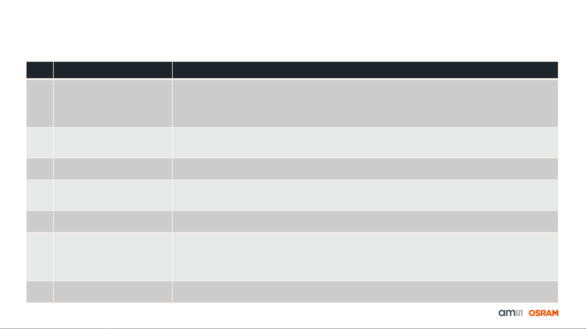
AS7050 SW Preset Configuration Files
Features of Configuration files for EVK
No. Name of Configuration File Features
1ECG 200 Hz, Gain 256 This is an optimized configuration preset for measuring ECG.
Sampling Frequency: 200 Hz
Total ECG gain: 4*64*1 = 256
High pass filter cutoff frequency (fc) = 0.33 Hz
Low Pass filter: Bypassed
2HRM 20 Hz In this configuration, the software-based AGC algorithm controls the PD-offset values and LED current to get an
optimum PPG signal on the finger. The HRM algorithm, that estimates the heart rate, is activated and the values are
displayed in the GUI.
3 SpO2 200 Hz Configuration for SpO2 measurements on the finger. The PPG sample rate is 200 Hz.
Note: This SpO2 configuration is uncalibrated.
4ECG 200 Hz, 1x PPG 100 Hz,
AOC
In this configuration, the two measurement channels, i.e. the ECG channel and the PPG channel, are active at the
same time. It allows the user to acquire the PPG and the ECG signals simultaneously. Automatic offset control
(AOC) is activated in the PPG channel to keep the ADC values in the defined range.
5PPG 200 Hz, ECG ADC, AGC This is a configuration for acquiring the PPG signal using the ECG channel by choosing TIA as the source of the
ECG signal. The AGC algorithm is activated to keep the ADC values in the defined range.
6 6x PPG 0-IR-0-R-0-G 100 Hz,
AOC
This is a configuration for acquiring six PPG sub-samples. Broadband PD is used as the detector in all the
measurements. As is apparent from the naming, in the odd-numbered sample (PPG1, PPG3, and PPG5), the LEDs
are switched OFF. For the even-numbered sub-samples (PPG2, PPG4, and PPG6), the IR, Red, and Green LEDs
are switched ON, respectively. The automatic offset control (AOC) is activated for each sub-sample to keep the ADC
values in the defined range.
7 GSR Measurement This is a test configuration for measuring the external resistance using the analog frontend.
Fig. 7: Features of the configuration files

10
AS7050 PC Software
Starting a HRM measurement
Fig. 8: Overview of the GUI (HRM measurement)
1. Firstly, press the sensor button ”S1”for 1 second
to power on the sensor.
2. Afterward, select the correct COM port number or
BLE MAC address from the drop-down menu.
3. Then, click the Connect button.
4. When it is successfully connected, button on the
left-hand side of the status bar (AS7050) will
change color to green (COM connection) and blue
(BLE connection).
5. The green LED on the Bluetooth module will start
blinking as soon as the board connects with the
GUI.In the case of a BLE connection, the LED will
blink blue instead.
6. After connecting, select the correct configuration
file from the configuration presets provided (EVK:
HRM 20 Hz using PPG signal) in the configuration
tab.
7. Then, click the Start Measurement button.
8. Finally, place a finger on the SFH7072 LED/PD
module, and subsequently, you will see the PPG
raw data plot in the Graph window and the heart
rate in the application output window.

11
AS7050 PC Software
Starting a SpO2 measurement
Fig. 9: Overview of the GUI (SpO2 measurement)
1. Firstly, press the sensor button ”S1”for 1 second
to power on the sensor.
2. Afterward, select the correct COM port number or
BLE MAC address from the drop-down menu.
3. Then, click the Connect button.
4. When it is successfully connected, the button on
the left-hand side of the status bar (AS7050) will
change color to green (COM connection) and blue
(BLE connection).
5. The green LED on the Bluetooth module will start
blinking as soon as the board connects with the
GUI.In the case of a BLE connection, the LED will
blink blue instead.
6. After connecting, select the correct configuration
file from the configuration presets provided (EVK:
SpO2 200 Hz using PPG signal) in the
configuration tab.
7. Then, click the Start Measurement button.
8. Finally, place a finger on the SFH7072 LED/PD
module, and subsequently, you will see the PPG
raw data plot in the Graph window and the heart
rate & SpO2 percentage in the application output
window.

12
AS7050 PC Software
Starting a ECG Raw Data measurement
Fig. 10: Overview of the GUI (EVK measurement)
1. Firstly, press the sensor button ”S1”for 1 second
to power on the sensor.
2. Afterward, select the correct COM port number or
BLE MAC address from the drop-down menu.
3. Then, click the Connect button.
4. When it is successfully connected, the button on
the left-hand side of the status bar (AS7050) will
change color to green (COM connection) and blue
(BLE connection).
5. The green LED on the Bluetooth module will start
blinking as soon as the board connects with the
GUI.In the case of a BLE connection, the LED will
blink blue instead.
6. After connecting, select the correct configuration
file from the configuration presets provided (EVK:
ECG 200 Hz, Gain 256 using Electrodes) in the
configuration tab.
7. Then, click the Start Measurement button.
8. Finally, place three fingers on the ECG electrodes,
and subsequently, you will see the ECG raw data
plot in the Graph window.

13
AS7050 PC Software
Starting a HRM & ECG raw data measurement
Fig. 11: Overview of the GUI (EVK measurement with PPG)
1. Firstly, press the sensor button ”S1”for 1 second
to power on the sensor.
2. Afterward, select the correct COM port number or
BLE number from the drop-down menu.
3. Then, click the Connect button.
4. When it is successfully connected, the button on
the left-hand side of the status bar (AS7050) will
change color to green (COM connection) and blue
(BLE connection).
5. The green LED on the Bluetooth module will start
to blink as soon as the board connects with the
GUI.In the case of a BLE connection, the LED will
blink blue instead.
6. After connecting, select the correct configuration
file from the configuration presets provided (EVK:
ECG 200 Hz, 1x PPG 100 Hz, AOC using PPG
signal & ECG electrodes) in the configuration tab.
7. Then, click the Start Measurement button.
8. Finally, place three fingers on the ECG electrodes
& a finger on the SFH7072 LED/PD module, and
subsequently, you will see the ECG & PPG raw
data plot in the Graph window and the heart rate
in the application output window.

14
AS7050 Register Map
Register Map Configuration
•To check the current register Map, click on the tab
File Register Map
•In the Register Map window,
oThe register values can be updated.
oNew register values can be entered.
oNew register values can be saved with a
name. Choose the file location, and then
click save.
Fig. 12: Register Map

15
AS7050 PC Software
Saving and Loading Configuration
•To load a configuration (JSON file), click on the tab File
Load Configuration. This will open the Select Configuration
File dialog box. Select the JSON configuration file you want to
load, and click Open.
•To save the current configuration settings, click on the tab File
Save Configuration. This will open the Save Configuration
File dialog box. Enter a file name, choose the file location,
and save it as a´.json file´. Then, click Save to save the file.
Fig. 13: Loading a Configuration File
Fig. 14: Saving a Configuration File

16
AS7050 PC Software
Raw data logging and exporting
•To save the measurement data, select Start Logging
under the Log tab. The GUI prompts the user to select a
file name and the data is saved in CSV format.
Optionally, the logging with a timestamp can be selected.
This enables automatic saving to subsequent
measurement results with file names that have a
timestamp.
Fig. 15: Logging of raw data

17
AS7050 Firmware upgrade
Optional FW upgrade over USB
Fig. 16: Update Firmware via the GUI
Fig. 17: Firmware update in progress
1. Obtain the latest “*.dfu”firmware file from ams OSRAM.
2. Click on the tab Help Firmware Update…to navigate
to the “*.dfu”file (latest firmware file).
3. During the update process, the green LED on the
Bluetooth module will turn red.
4. After a successful update, the red LED will turn green
again.
Note: If the firmware update fails, wait 10 seconds and
restart the board by pressing the S1 button.
•Note: The latest firmware is available for download (please contact the ams OSRAM support team (support_aws@ams-osram.com) for the download link)

Sensing is life
Table of contents
Other Osram Motherboard manuals