OSTBERG HERU 62 T Manual

SVENSK/ENGLISH VERSION
Bruksanvisning
Directions for use
HERU®62 T, HERU®90 T, HERU®90 T EC 2
HERU®115 T, HERU®130 T EC, HERU®140 T
HERU®50 S 2A, HERU®75 S 2A, HERU®90 S EC 2A
HERU®130 S 2A, HERU®130 S EC 2A
HERU®180 S 2A, HERU®180 S EC 2A

AGGREGATBESKRIVNING . . . . . . . . . . . . . . . . . . .3
INSTALLATION OCH SÄKERHET . . . . . . . . . . . . . .4
”NYTTJANDE””SÄKERHET””GARANTI””MONTAGE” . . . .4
”PLACERING””FRITT UTRYMME” . . . . . . . . . . . . . . . . . . .5
”PRINCIPSKISSER PLACERING”. . . . . . . . . . . . . . . . . . . . .6
”MONTAGEANVISNINGAR” . . . . . . . . . . . . . . . . . . . . . .7-9
UPPSTART . . . . . . . . . . . . . . . . . . . . . . . . . . . . . .10
REGLERSCHEMAN . . . . . . . . . . . . . . . . . . . . .23-12
KOPPLINGSSCHEMAN . . . . . . . . . . . . . . . . . .13-22
REGLERFUNKTIONER . . . . . . . . . . . . . . . . . . . . .23
MENYHANTERING . . . . . . . . . . . . . . . . . . . . . . .24
VISNINGSLÄGEN 1-4 . . . . . . . . . . . . . . . . . . . . .25
HUVUDMENY . . . . . . . . . . . . . . . . . . . . . . . . . . .26
MENY ”FLÄKTHASTIGHET” . . . . . . . . . . . . . . . .26
MENY ”TEMPERATUR” . . . . . . . . . . . . . . . . . . . .26
MENY ”FORCERING” . . . . . . . . . . . . . . . . . . . . .26
MENY ”TRYCKKOMPENSERING” . . . . . . . . . . . .27
MENY ”VECKOUR” . . . . . . . . . . . . . . . . . . . . . . .27
MENY ”HERU PÅ/AV” . . . . . . . . . . . . . . . . . . . .28
MENY ”LARM” . . . . . . . . . . . . . . . . . . . . . . . . . .28
MENY ”INSTÄLLNINGAR” . . . . . . . . . . . . . . . . .29
MENY ”SERVICEMENY” . . . . . . . . . . . . . . . .29-37
”KONSTANT TRYCK” ”TRYCKGIVARE” . . . . . . . . . . . . .30
”FILTERMÄTNING” ”EC-MOTOR SETUP”
”AC-MOTOR SETUP” . . . . . . . . . . . . . . . . . . . . . . . . . . .31
”DISPLAY KONTRAST” ”FORCERING”
”TRYCKKOMPENSERING” . . . . . . . . . . . . . . . . . . . . . . .32
”LARM” ”CO2” . . . . . . . . . . . . . . . . . . . . . . . . . . . . . . .33
”RH” ”EFTERVÄRMARE” ”KYLVATTENBATTERI” . . . . . .34
”TILLUFTSGRÄNS” ”REGLERTYP” ”SOMMARKYLA” . . .35
FRYSSKYDD” ”FLÖDESRIKTNING”
”LADDA/SPARA” ”VERSION INFO” . . . . . . . . . . . . . . . . .36
”MANÖVERENHET” . . . . . . . . . . . . . . . . . . . . . . . . . . . .37
ÖVRIGA FUNKTIONER . . . . . . . . . . . . . . . . . . . .37
MÅTTSKISSER . . . . . . . . . . . . . . . . . . . . . . . .38-39
TEKNISKA DATA . . . . . . . . . . . . . . . . . . . . . . . . .40
LJUDDATA . . . . . . . . . . . . . . . . . . . . . . . . . . .41-51
TRYCK- OCH FLÖDESDIAGRAM . . . . . . . . . .52-56
SERVICE HERU T . . . . . . . . . . . . . . . . . . . . . . . . . .57
SERVICE HERU S . . . . . . . . . . . . . . . . . . . . . . .58-59
SKIFTE AV ELEKTRISK EFTERVÄRMARE . . . . . .60
TILLBEHÖR . . . . . . . . . . . . . . . . . . . . . . . . . . . . .61
RESERVDELSFÖRTECKNING . . . . . . . . . . . . . . . .62
FELSÖKNING . . . . . . . . . . . . . . . . . . . . . . . . . . . .63
FELSÖKNINGSSCHEMA . . . . . . . . . . . . . . . . .64-65
EGNA INSTÄLLNINGAR . . . . . . . . . . . . . . . . .66-67
EG-FÖRSÄKRAN . . . . . . . . . . . . . . . . . . . . . . . . .68
UNIT DESCRIPTION . . . . . . . . . . . . . . . . . . . . . . .71
INSTALLATION AND SECURITY . . . . . . . . . . . . .72
”USE” ”SECURITY” ”MOUNTING””WARRANTY” . . . . .72
”PLACING” ”FREE SPACE” . . . . . . . . . . . . . . . . . . . . . .73
”SCHEMATIC DIAGRAMS FOR PLACING” . . . . . . . . . . .74
”ASSEMBLY INSTRUCTIONS” . . . . . . . . . . . . . . . . . .75-77
STARTING UP THE UNIT . . . . . . . . . . . . . . . . . . .78
CONTROL DIAGRAMS . . . . . . . . . . . . . . . . . .79-80
WIRING DIAGRAMS . . . . . . . . . . . . . . . . . . .81-90
REGULATION FUNCTIONS . . . . . . . . . . . . . . . . .91
OPERATING THE CONTROL UNIT . . . . . . . . . . .92
VIEW MODES 1-4 . . . . . . . . . . . . . . . . . . . . . . . .93
MAIN MENU . . . . . . . . . . . . . . . . . . . . . . . . . . . .94
”FAN SPEED” MENU . . . . . . . . . . . . . . . . . . . . . .94
”TEMPERATURE” MENU . . . . . . . . . . . . . . . . . . .94
”BOOST” MENU . . . . . . . . . . . . . . . . . . . . . . . . .94
”OVERPRESSURE” MENU . . . . . . . . . . . . . . . . . .95
”WEEK TIMER” MENU . . . . . . . . . . . . . . . . . . . .95
”UNIT ON/OFF” MENU . . . . . . . . . . . . . . . . . . . .96
”ALARMS” MENU . . . . . . . . . . . . . . . . . . . . . . . .96
”SETTINGS” MENU . . . . . . . . . . . . . . . . . . . . . . .97
THE ”SERVICE MENU” . . . . . . . . . . . . . . . . . .97-33
”CONSTANT PRESSURE” ”PRESSURE INPUTS” . . . . . . . .98
”FILTER MEASUREMENT””EC FAN SETUP”
”AC FAN SETUP” . . . . . . . . . . . . . . . . . . . . . . . . . . . . . .99
”DISPLAY CONTRAST” ”BOOST” ”OVERPRESSURE” . .100
”ALARM””CO2” . . . . . . . . . . . . . . . . . . . . . . . . . . . . .101
”RH” ”HEATER” ”COOLER” . . . . . . . . . . . . . . . . . . . .102
”SUPPLY LIMITS” ”REGULATION MODE”
”SUMMER COOLING” . . . . . . . . . . . . . . . . . . . . . . . . .103
”FREEZE PROTECTION”FLOW DIRECTION”
”LOAD/SAVE SETTINGS” ”VERSION INFO” . . . . . . . . . .104
”DEVICE PAIRS” . . . . . . . . . . . . . . . . . . . . . . . . . . . . . . .105
OTHER FUNCTIONS . . . . . . . . . . . . . . . . . . . . .105
DIMENSIONS . . . . . . . . . . . . . . . . . . . . . . .106-107
TECHNICAL DATA . . . . . . . . . . . . . . . . . . . . . . .108
SOUND DATA . . . . . . . . . . . . . . . . . . . . . .109-119
PRESSURE/FLOW DIAGRAMS . . . . . . . . . .120-124
SERVICE HERU T . . . . . . . . . . . . . . . . . . . . . . . . .125
SERVICE HERU S . . . . . . . . . . . . . . . . . . . . .126-127
CHANGE PLACE OF THE HEATER . . . . . . . . . . .128
ACCESSORIES . . . . . . . . . . . . . . . . . . . . . . . . . .129
SPARE PARTS . . . . . . . . . . . . . . . . . . . . . . . . . .130
ERROR DETECTION . . . . . . . . . . . . . . . . . . . . . .131
ERROR DETECTION DIAGRAM . . . . . . . . .132-133
INTERNAL SETTINGS . . . . . . . . . . . . . . . . .134-135
EC DECLARATION . . . . . . . . . . . . . . . . . . . . . . . .69
INNEHÅLL 3 CONTENTS 70
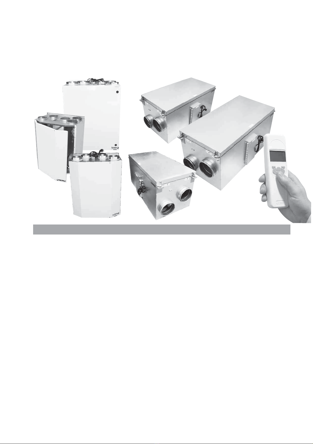
UNIT DESCRIPTION
• There are two models of the energy recovery unit
HERU®; T and S with AC or EC motors. They are
designed for supply and exhaust air ventilation
combined with heat and cool recovery.
• HERU®can be used in homes, offices, apartments
etc. where there is a need for:
-high temperature efficiency
-energy saving
-low sound levels
-safe operation
• HERU®has;
- a rotating heat exchanger, of non-hygroscopic
type and is manufactured of aluminium, placed
centrally in the unit. The heat exchanger has a
temperature efficiency of up to 86%.
- forward- or backwardcurved centrifugal fans with
maintenance free external rotor motors, which are
connected with quick contacts, and are easily to re-
move for cleaning.
- a built-in electric heater with pulser.
- as standard, disposable rigid filter F7 (HERU®T)
and bagfilter F7 (HERU®S).
- a wireless remote controller for the operation and
monitoring of the unit.
- a double skinned galvanised sheet steel casing
with 17 mm insulation (HERU®T) respective 50
mm intermediate insulation (HERU®S).
• The HERU®T is mounted in a warm space as e.g.
the utility room. The HERU®S can be mounted in
either warm or cold space.
• The HERU®T is delivered in white as standard and
the HERU®S is galvanised.
• HERU®EC is operated via a wireless remote con-
troller which can operate and to preset the requi-
red parameters as well as monitor the unit’s status.
The operating range is approximately 50 meters.
The antenna which is placed next to the unit can
have the range reduced if there are heavy reinfor-
cing bars in the concrete structure and it should
then be moved either to a position where the sig-
nal is not shielded or nearer to the controller.
• All HERU®units are equipped with a wall plug
except for HERU®180 S which has an access cable.
• HERU®90 T EC 2 has an integrated silencer.
71
This ”Direction for use” contains following products:
HERU®62 T, HERU®90 T, HERU®90 T EC 2, HERU®115 T,
HERU®130 T EC, HERU®140 T,
HERU®50 S 2A, HERU®75 S 2A, HERU®90 S EC 2A, HERU®130 S 2A,
HERU®130 S EC 2A, HERU®180 S 2A and HERU®180 S EC 2A
HERU®90 T EC 2
HERU®115 T
HERU®130 T EC
HERU®140 T
HERU®62 T
HERU®90 T
HERU®180 S 2A
HERU®180 S EC 2A
HERU®50 S 2A
HERU®75 S 2A
HERU®90 S EC 2A
HERU®130 S 2A
HERU®130 S EC 2A

72
INSTALLATION AND SECURITY
USE
• When installing HERU®consideration must be
given to any approval authority requirements and
recommendations concerning siting, accessibility,
electrical connections, etc.
• The HERU®unit is accessible for the user, accor-
ding to IEC 60335-2-40, to by themselves do the
service and maintenance, according to this
Directions for use. But before this work the unit
must be currentless.
With reservation according to IEC 60335-2-7.12
”This appliance is not intended for use by persons
(including children) with reduced physical, senso-
ry or metal capabilities, or lack of experience and
knowledge, unless they have been given supervi-
sion or instruction concerning use of the appliance
by a person responsible for their safety.”
”Children should be supervised to ensure that they
do not play with the appliance.”
• The HERU®unit should be storage in a sheltered
and dry place before installation.
• Dimensioned air flow should not exceed 60% of
the unit's maximum capacity.
• Check at regular intervals that supply air and ex-
haust air works.
•To avoid condensation in the unit during the cold
season, the unit should not be turned off for a
longer period. When installed in warm moisturre
environment as e.g. bathroom and utilityroom con-
dense may appear on the outside of the unit at low
outside temperatures.
SECURITY
• Attention, look out for sharp edges and corners on
the HERU®unit and fans.
• Consider the weight of the unit. See page 108.
• Before maintenance work the HERU®unit must be
currentless. If there is a need of changing or comp-
lement any electrical components, it should be
done by a qualified person.
• The HERU®unit includes rotating parts that could
cause serious danger on the occasion of contact.
This is why the unit must be duct connected and
the lid closed with the screws tightened, before
starting up the unit.
• After the current is cut for service and maintenan-
ce the electric heater may still be warm.
• Make sure that the access cable is not damage at
mounting and installation.
• HERU®must be equipped with earth fault breaker.
• The HERU®180 S needs a permanent electrical
supply. The unit must be connected via a safety
switch. Any electrical connections must be made
by a qualified electrician.
MOUNTING THE HERU®T
• The HERU®T should be installed according to the
assembly instruction on pages 75-76.
• The unit should be fixed on the wall with faste-
ners gear to the construction of the wall.
• Avoid mounting on a wall adjacent to bedroom.
• The unit should be mounted on an insulated wall.
• Use duct clamp or flange with encompassing insu-
lation when connecting to duct.
• If the supply and the exhaust air ducts are installed
in a cold space they should be insulated. To pre-
vent condensation the supply air duct should also
be insulated if installed in warm space at low supp-
ly air temperatures.
• The fresh air and extract air duct should always be
condense insulated.
• The ducts should be insulated all the way towards
the unit.
• The duct sensor GT7 is mount in the supply air
duct, and the antenna on a suitably position beside
the unit (not against metal).
• Acoustic silencer should be planned with the help
of sound data and required sound levels.
• If a heating coil is connected a cut off damper must
be mounted in the fresh air duct.
• Cooker hood (available as an assessory) can be
connected to HERU®62 T, 90 T, 115 T, 130 T EC
and 140 T where the exhaust air is not passing
through filter or the heat exchanger.
• Consider that kitchen ducts in houses must be
mounted with the lowest fire resistance class E15
and with a safety distance of minimum 30 mm to
combustible material. The kichen duct must also
be equipped with a cleaning door.
MOUNTING THE HERU®S
• HERU®S should be installed according to the
assembly instruction on page 77.
• Place the unit on a ground board, min. 50 mm.
• Supply and exhaust air must be duct connected on
the same side of the unit.
• Acoustic silencer should be planned with the help
of sound data and required sound levels.
• Use duct clamp or flange with encompassing insu-
lation when connecting to duct.
• If the supply and the exhaust air ducts are installed
in a cold space they should be insulated. To pre-
vent condensation the supply air duct should also
be insulated if installed in warm space at low supp-
ly air temperatures.
• The fresh air and extract air duct should always be
condense insulated.
• The ducts should be insulated all the way towards
the unit.
• The duct sensor GT7 is mount in the supply air
duct, and the antenna on a suitably position beside
the unit (not against metal).
• If a heating coil is connected a cut off damper must
be mounted in the fresh air duct.
• Cooker hoods must not be connected to the
HERU®S because of the increased cleaning de-
mand.
• Ducting must be conntec-
ted to external ground on
the unit, see picture.
WARRANTY
The warranty is only valid under condition that the
HERU®unit is used according to this ”Directions for
Use” and a regular maintenance has been record.
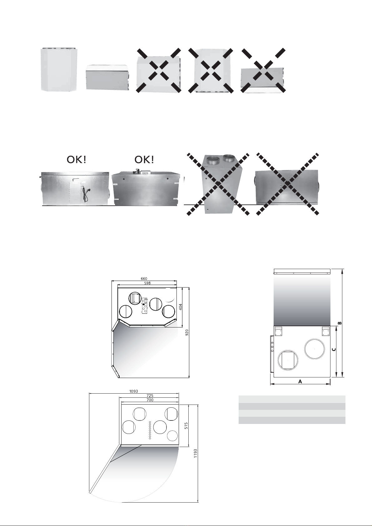
The HERU®T should be installed with the duct connections upwards (A) but can also be placed decumbently (B).
We do not recommend installing the unit on one side (C), with the duct connections (D) or lid downwards (E).
Allowances must be made to access the unit for servicing or maintenance.
PLACING THE HERU®T UNIT
FREE SPACE FOR SERVICE AND MAINTENANCE
73
PLACING THE HERU®S UNIT
The HERU®S should be installed with the lid upwards (A) or on the side (B), we do not recommend
installing the unit vertically (C) or with the lid downwards (D). Allowances must be made to access the unit for
servicing or maintenance.
HERU®62 T, 90 T,
90 T EC 2
Max aperture
angle 90°.
HERU®115 T,
130 T EC, 140 T
Max aperture
angle 130°.
C D E
A B
OK! OK!
A B C D
HERU®S
Fee space
for service
and
maintenance.
mm A B C
H E R U®50 S 2A, 75 S 2A, 90 S EC 2A 555 800 420
H E R U®130 S 2A, 130 S EC 2A 605 1000 521
H E R U®180 S 2A, 180 S EC 2A 715 1220 631

SCHEMATIC DIAGRAM FOR HERU®T EC PLACED IN A WARM SPACE
SCHEMATIC DIAGRAM FOR HERU®S PLACED IN AN ATIC
74

1.
ASSEMBLY INSTRUCTION FOR HERU®90 T EC 2
Mount the unit with concomitant rubber cushions and adequate screws for the foundation.
NB! The concomitant rubber cushions can be compressed to a thickness of maximum 10 mm.
The unit is not supplied with wall screws.
Fasten two small adhesive rubber cushions
on the backside, in both corners at the bottom
of the unit
2.
Fasten the wall bracket
with two lock washers,
3 rubber cushions and
adequate screws.
3.
Suspend the unit on the
wall bracket and secure
with two screws 4,2 x 9,5.
75

Mount the unit with concomitant rubber cushions and adequate screws for the foundation.
NB! The concomitant rubber cushions can be compressed to a thickness of maximum 10 mm.
The unit is not supplied with wall screws.
C
B
ASSEMBLY INSTRUCTION FOR HERU®130 T EC
1.
Unscrew the
wall bracket.
2.
Turn the wall bracket
180oand fasten on to
the wall with 4 rubber
cushions and adequate
screws.
3.
Place the unit on to the
wall bracket and fasten
with 4 rubber cushions
and adequate screws.
4.
Fasten the unit on to the wall
bracket with the two removed
screws.
3.
There is also a floor stand to
HERU 130 T EC as an asses-
sory. Start by remove the wall
bracket (1).
Then mount the floor stand
according to illustration (B).
Adjust the feets (C) so the
unit stands steady.
Fasten the unit on to the
wall (3).
76

77
ASSEMBLY INSTRUCTION FOR HERU®S
INSULATING
BOARD
min.
50 mm
E.G. PLYWOOD TIGHTENED TO JOISTS

SUPPLY
AIR
EXHAUST
AIR
FRESH
AIR
EXTRACT
COOKER
HOOD
EXHAUST
AIR
HERU®130 T EC
78
STARTING UP THE UNIT
NB! Important information before starting!
Carefully read through the manual before starting
up the unit.
• NB! Always mount the temperature sensor GT7 in
the supply air duct. See page 79-80. GT7 is connec-
ted at the relay card. The temperature sensor GT7
for HERU®S EC is in the connection box when
delivered. For HERU®90 T EC2 the GT7 is moun-
ted in the unit.
• The antenna should be mounted outside the unit.
The antenna for HERU®is delivered connected,
and for HERU®S it is in the connection box.
NB! The antenna should not be mounted against
any metal area or metal items as this will shield
the signal.
The antenna should be mounted as central as
possible. This to acchive the best signal all over
the house. If neede an extension cord is available
as an accessorie.
• Install the 3 AA batteries in the wireless control
unit that are placed inside the HERU®when deli-
vered.
• HERU®EC starts automatically (with a few minu-
tes delay) when the current is switched on, or
alternative with the wireless control unit. At power
outage, always check so the unit is starting up
again.
•HERU®S is supplied for right handing applica-
tion, see picture below. If the unit is installed left
handed then changes can be made in the ”Service
Menu” and in the submenu ”Flow Direction”.
See page 104.
NB! If left handing application, the electrical hea-
ter must be moved. See page 128.
• Important when adjusting the flow: Go to Service
Menu (password 1199), choose “AC -motor setup”
or “EC-motor setup”. This disable functions such as
Summer cooling or Boost during flow adjustment.
The fan speed is standard. See page 100.
When adjusting the airflow of AC-fans there is a
possibility to change the voltage for the different
fan speeds via the separate transformers-
rerna for supply resp. exhaust fan. Normal opera-
tion should be done in standard mode.
HERU®50/75 S has 5-step transformers and
HERU®130/180 S has 7-step. See wiring diagrams
on pages 81, 83, 85, 87 and 89.
NB! When ajusting fan speed manully, make sure
that the speed keeps the sequences.
• All HERU®has an electric heater as standard.
Choose heater ”On/Off” according to the instruc-
tion on page 102. För external Heater see instruc-
tion on page 102.
• Set the temperature
according to the
instruction
on page 94.
• Save settings
according to the
instruction on
page 104.
•NB! The unit
must not be
operating
without filter.
SUPPLY
AIR
EXHAUST
AIR
FRESH
AIR
EXTRACT
AIR
SUPPLY
AIR
FRESH
AIR
EXTRACT
AIR
EXHAUST
AIR
HERU®90 T EC 2
HERU®S

79
CONTROL DIAGRAM HERU®T
shows all sensors
HERU®90 T EC 2:
HERU®62 T,
HERU®90 T,
HERU®115 T,
HERU®130 T EC,
HERU®140 T:
TF
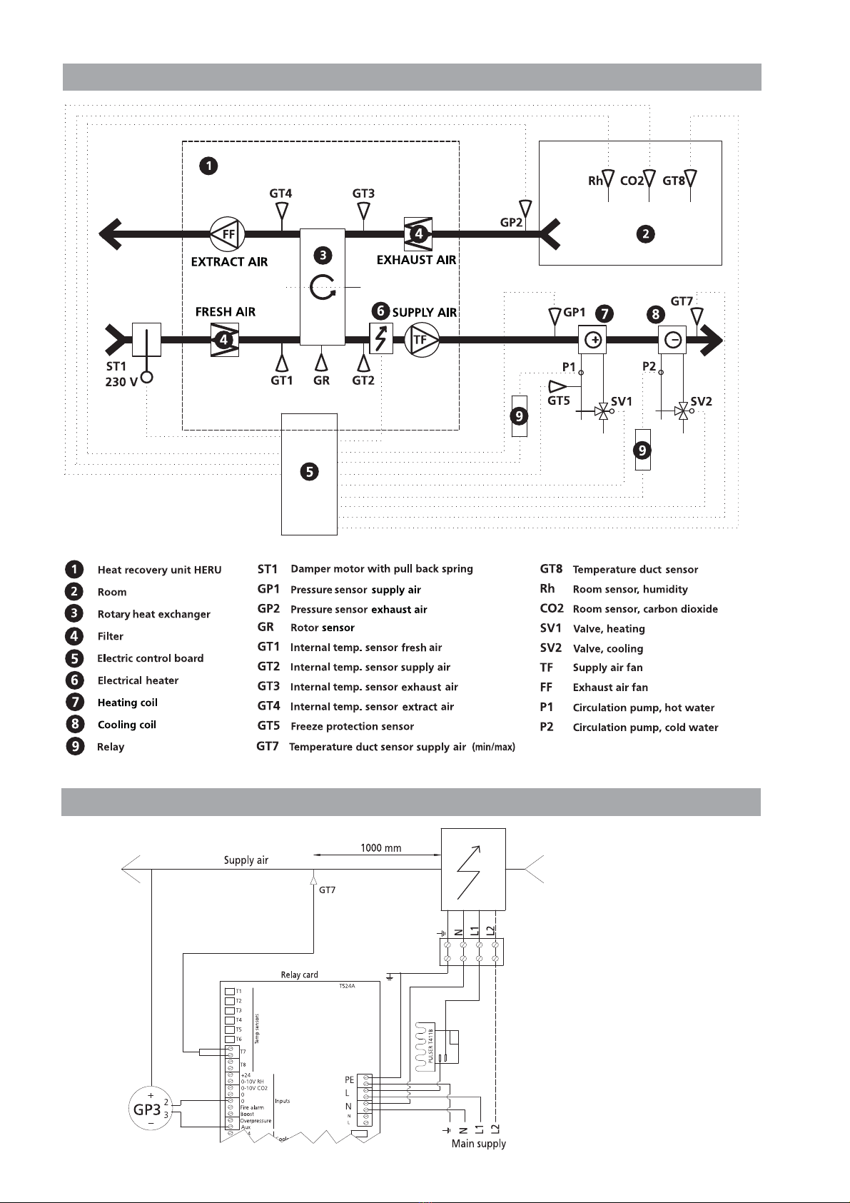
CONTROL DIAGRAM HERU®S
shows all sensors
Duct heater 2-phase 400 V. L1, L2
Single phase 230 V. N, L1
WIRING DIAGRAM for electrical duct heater
80
81
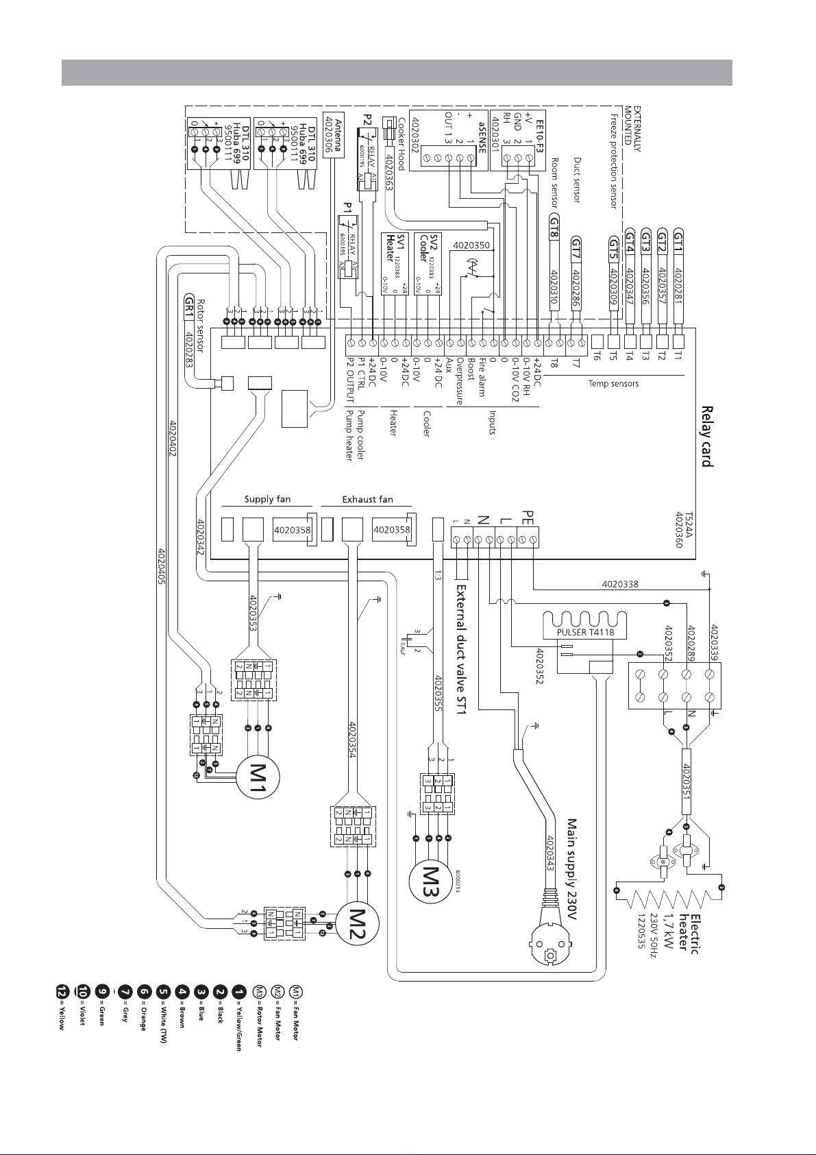
WIRING DIAGRAM 4040118 HERU®62 T/90 T
Min. fan speed
Max. fan speed
Medium fan speed
Normal fan speed

82
WIRING DIAGRAM 4040141 HERU®90 T EC 2
4020336
4020277
4020275
4020427

83
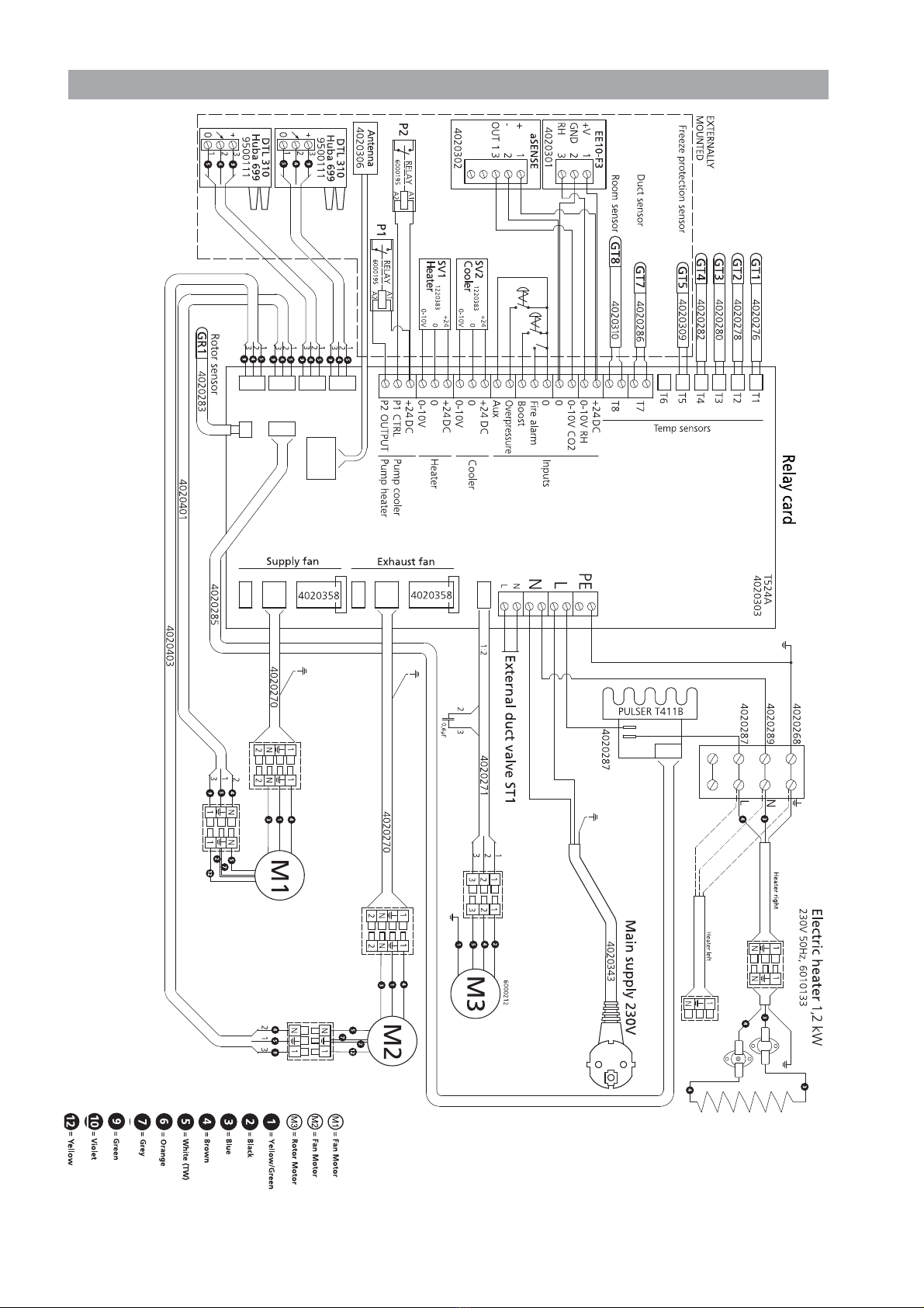
WIRING DIAGRAM 4040120 HERU®115 T/140 T
Min. fan speed
Max. fan speed
Medium fan speed
Normal fan speed
84
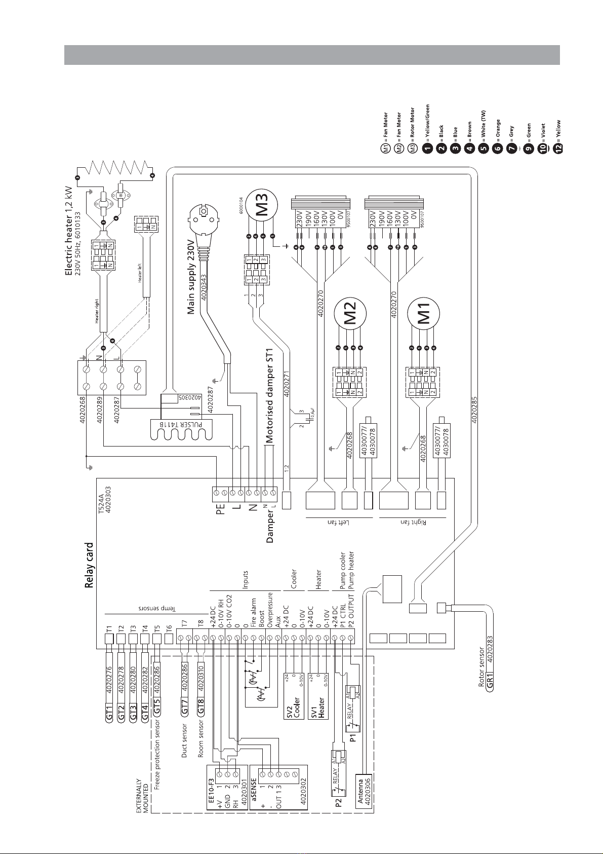
WIRING DIAGRAM 4040136 HERU®130 T EC
WIRING DIAGRAM 4040106 HERU®50 S A2/75 S 2A
85
Min. fan speed
Max. fan speed
Medium fan speed
Normal fan speed
86
WIRING DIAGRAM 4040134 HERU®90 S EC 2A

87
WIRING DIAGRAM 4040107 HERU®130 S 2A
Min. fan speed
Max. fan speed
Medium fan speed
Normal fan speed

88
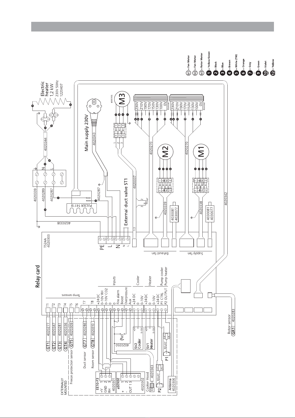
WIRING DIAGRAM 4040119 HERU®130 S EC 2A
This manual suits for next models
12
Table of contents
Other OSTBERG Heating System manuals


Popular Heating System manuals by other brands


aerauliqa
aerauliqa DWE4120 Installation, use and maintenance manual

Frico
Frico Aquaztrip H Service & Maintenance

Bryant
Bryant 379 Product data sheet

Cetetherm
Cetetherm Midi Wall TA Installation, service and operating instruction

Laars
Laars Mighty Therm 2 Installation and operation

2VV
2VV DAPHNE Installation

nuair
nuair NU0103 OPERATING, MAINTAINING & INSTALLING

System air
System air SAVE VTR 150/K user manual

Magic-Pak
Magic-Pak HWC8 V Series installation instructions

System air
System air SAVE VTC 700 user manual

System air
System air SAVE-P VSR 150/B installation instructions

Mark
Mark ERV Series Technical manual