89
2 VV. Creating innovative solutions for you and your business since 1995.
6. INSTALLATION
The unit is not designed to lter air containing combustible
or ammable particles, chemical fumes, coarse dust, carbon,
grease, poisons, bacteria, etc.
The IP protection level of the unit in the ducts is IP 20 (protec-
tion against objects bigger than 12.5 mm, does not protect
against water).
Installation distance
These dimensions are suitable for service access.
* it is necessary o leave enough space to connect a sink.
TECHNICAL INFORMATION
• All the models of the heat recovery unit can be installed in
the following positions:
• Any other position is forbidden.
• The unit must be installed so that the direction of the air cir-
culation will correspond with the air circulation in the distribu-
tion system.
• The installation must allow access for maintenance, service or
disassembling. Access relates mainly to opening the revision
lid.
600 mm
Your partner in ventilation...
INSTALLATION AND ASSEMBLY
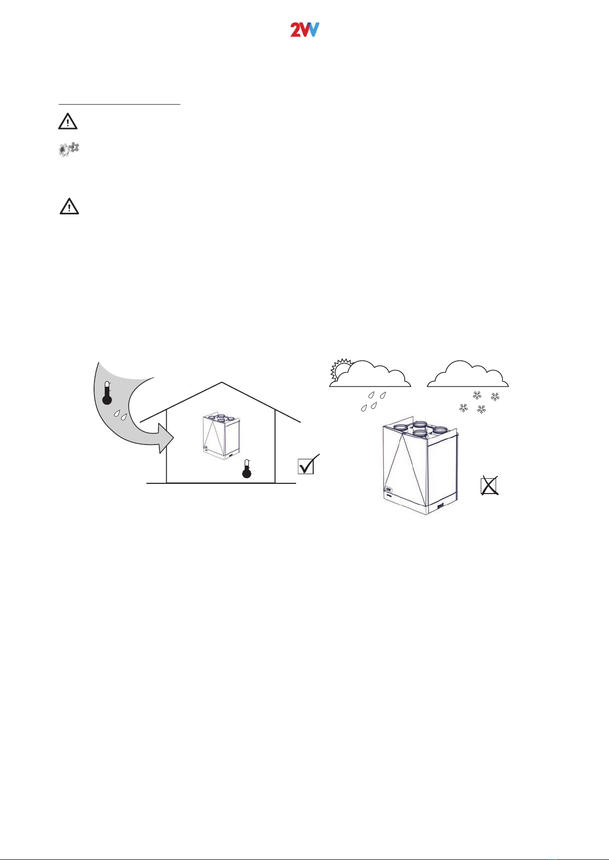
The unit is designed for installation in the vertical position.
Other installation position is not possible.
Installation of the unit shall allow a sufficient access for
performing maintenance, servicing, and dismounting
operations.
AUFSTELLUNG UND AUFBAU
Das Gerät ist zum Einbau in vertikaler Position bestimmt.
Andere Einbauposition ist nicht möglich.
Das Gerät muss so installiert sein, dass ein ausreichender
Zugang zwecksWartung, Service, oder deren Demontage
garantiert wird.
- The unit is fixed using suspension holders located on both
sidewalls of the unit.
- The unit shall be fixed safely to avoid its dropping.
- No flammable materials are allowed within 100 mm of the
unit housing and within 500 mm of the inlet sleeve of theunit.
- The air duct is connected by slipping it over the circular neck
with a rubber sealing ring
- It is necessary to install a siphon (accessory) to the
condensate exhaust
- The minimal degree of incline of the siphon is calculated
according to the formula (see Calculation of siphon height)
- Das Gerät wird mit Anhängehaltern an beiden Seiten des
Gerätes befestigt
- Das Gerät ist so zu befestigen, dass diese nicht abstürzen
kann
- in der Entfernung 100 mm vom Gehäuse des Gerätes und 500
mm vom Eingangsstutzen des Gerätes dürfen sich keine
brennbaren Stoffe befinden
- Der Anschluss der Luftleitung erfolgt durch Aufschieben auf
die Rundstutzen mit einem Gummidichtungsring.
- Für die Kondensatausscheidung muss ein Siphon (Zubehör)
installiert werden.
- Die minimale Überhöhung des Siphons berechnet sich nach
der unter „Berechnung der Siphonhöhe“ genannten Formel.
Necessary space for service
Notwendiger Servisraum
200 mm 200 mm
200 mm
Produced in EU
HEAT RECOVERY WÄRMERUECKGEWINNUNG
The company reserves the right of change without previous announcement. ©2VV, spol. s r.o.
320
ISIS Recover HR-A
Required distance
ATTENTION
The intake and exhaust vents must not be blocked by non-
combustible material.
• The safe distance between combustible materials and the in-
take is 250 mm.
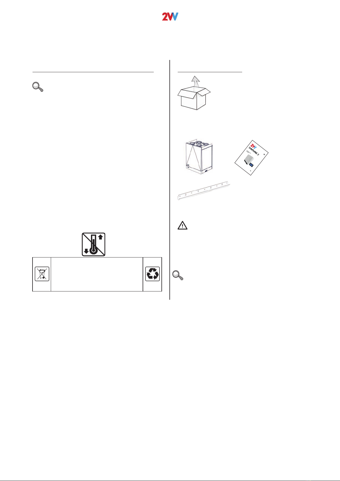
Installing the unit
• Service doors can be mounted in the place of the rear
panel of the unit and thereby reverse the HVAC connec-
tion and condensate exhaust.
*mm
A
Installation on wall
Dimensions of the wall bracket:
(included)
Fix the bracket appropriately with 4 M8x80 screws and
washers.
(non included)
• Measure the location appropriately.
• Drill holes in the wall and x the bracket included.
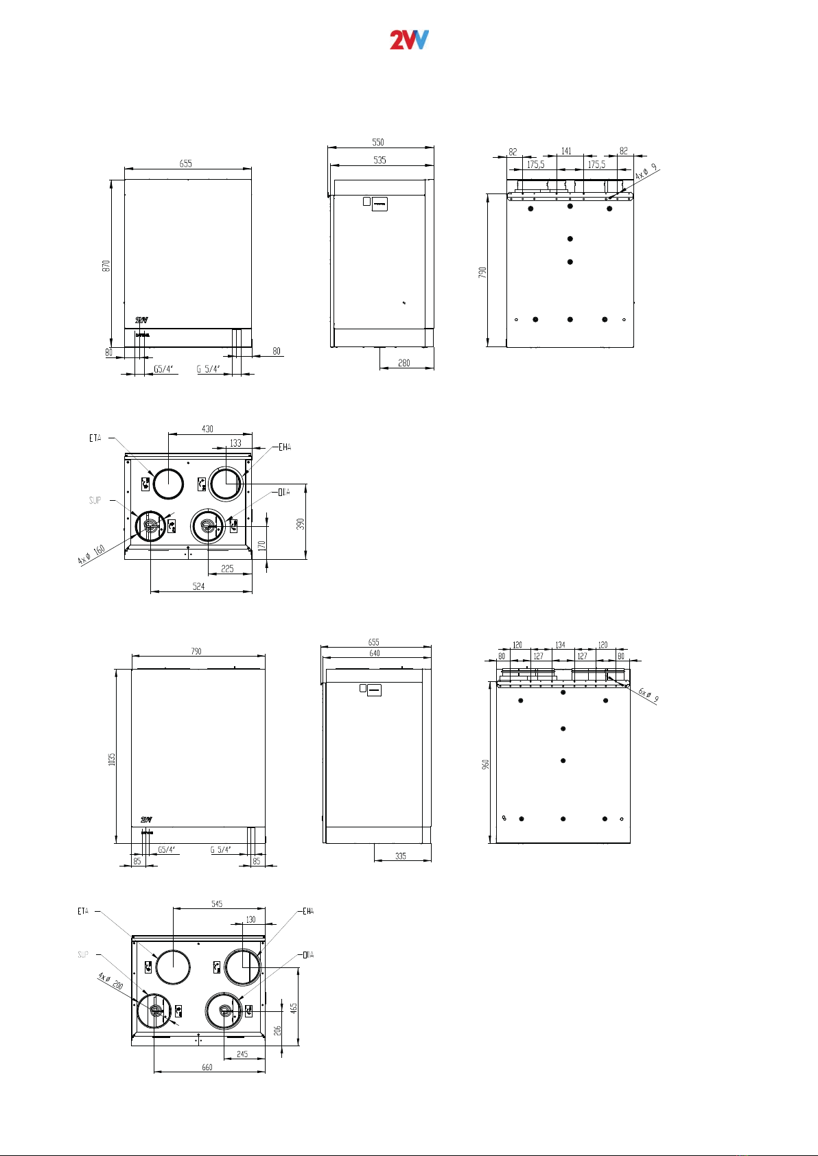
HRDA2-020 / HRDA2-030
A
HRDA2-020 min. 250mm
HRDA2-030 min. 350mm
HRDA2-050 min. 500mm
HRDA2-070 min. 700 mm
HRDA2-090 min. 700 mm
00
127 127
134
175,5 175,5
HRDA2-050 / HRDA2-070 / HRDA2-090