Ostro Furniture AOF-C3D03 User manual
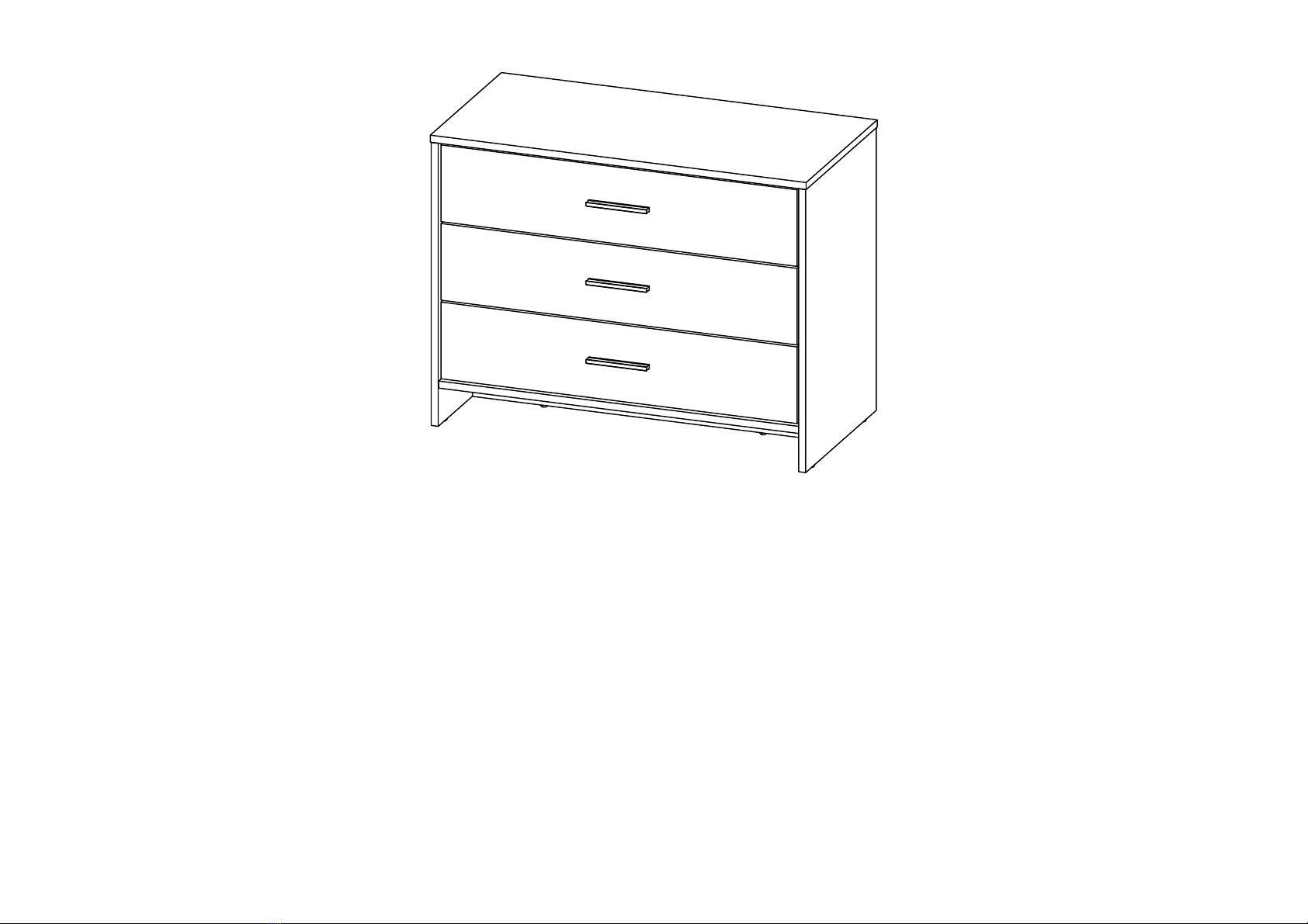
Three Drawer Lowboy
Assembly Instructions
Model Number: AOF-C3D03
AFTER SALES SUPPORT
(AU) 1300 886 649 (NZ) 0800 836 761
1

Personnel: 2 Adults
Assembly Requirements
Quickfit/Cam Lock Guide
To use the quickfit/cam lock, first
insert the quickfit into the panel. The
“shoulder” of the quickfit should be
flush against the panel, as shown in (a).
When inserting the cam lock, ensure
the orientation is correct, as shown, so
that it aligns properly with the quickfit,
as shown in (b) and (c).
Once the panels have been connected,
tighten the cam lock with a
screwdriver (d).
Space: 2 x 2 m Time: 1.5 hours
Shoulder
a)
b)
c) d)
2

IMPORTANT: Please read this manual carefully, and keep it for future reference.
•This piece of furniture is intended for use in domestic environments. It is not suitable for commercial, industrial or trade
use. Do not use it for any other purpose, and only use it as described in this manual.
•Assembly to be carried out by a competent adult only. Please check all parts and hardware are available and
undamaged before use.
•During assembly children should be kept away from the product due to possible risk of injury.
•Do not use this item if any components are missing or damaged.
•Regularly check all fastenings to ensure that they properly tightened.
•Do not use the unit outdoors. It is for indoor use only.
•Keep away from fire and heat sources.
•Be aware of the risk of open fires and other sources of strong heat in the vicinity of the product.
•Do not use this product in a bathroom or laundry, or where it can be splashed with water.
•This item of furniture is not intended to be assembled by persons (including children) with reduced physical, sensory or
mental capabilities, or lack of experience and knowledge.
•Handle this product with care. Do not shake the product vigorously or drop it from an elevation. Doing so will damage
the product or shorten its lifespan. Do not sit or stand on the item of furniture, which may lead to potential injury. Do not
press hard on top of the unit or place very heavy things on top of it.
•Always place the product on a dry, stable, level and horizontal surface. Never place it on an inclined or uneven surface.
•Do not locate the item of furniture near appliances that get hot during use, such as heaters, ovens or fireplaces. Avoid
long-term exposure to direct sunshine.
•We accept no responsibility for any eventual injury or damage caused by improper installation, misuse or noncompliance
with the instructions.
•These instructions are not intended to cover every possible condition and situation. As with any product, common sense
and caution are therefore always recommended when assembling, using and maintaining the item of furniture.
•Do not over-tighten fixtures.
•Power tools are not recommended for assembly.
•This item of furniture is heavy - take care when moving it. Multiple people or a mechanical aid may be required.
Important Safety Information
3

• CAUTION: Do not allow children to climb on this furniture - it may topple over and badly injure a child. Do not place toys
or other items that may appeal to a child on top of this furniture item.
• CAUTION: Attachment of this item of furniture must be attached to an appropriate structural component of the building
using suitable means, as advised by a qualified tradesperson, is strongly recommended.
Care and Maintenance:
• Ensure that all fastenings and fixtures have been sufficiently tightened. You may need to re-tighten periodically, as
necessary.
• To clean, wipe clean with a damp cloth, before drying thoroughly.
• Do not place hot or wet items on the surface.
• Do not drag or pull your furniture.
Important Safety Information
Responsible disposal
Packaging materials are recyclable.
Please dispose of them responsibly
for recycling.
At the end of its working life, do
not throw this item of furniture out
with your household waste. Please
dispose of this product at your
local community’s waste collection/
recycling centre. Observe any local
regulations regarding the disposal of
this type of product.
NOTE: Due to continued product improvement, images
and illustrations in this manual may vary slightly from the
product purchased. All images in this set of assembly
instructions are for reference purposes only. Parts are not
necessarily pictured to scale.
4
ASSEMBLY INSTRUCTIONS
5
Read instruction carefully . See Furniture Parts list and Hardware List for guidance . Be sure you have all parts before you start assembling .
Place and assemble furniture on a clean flat soft surface , such as carpet or rug to pervent being scratched .
Before you begin, please follow assembly instructions carefully, then follow them step by step.
Reminder:
Please ensure that all surfaces and edges with colours/laminations are facing forward/outward.
1
2
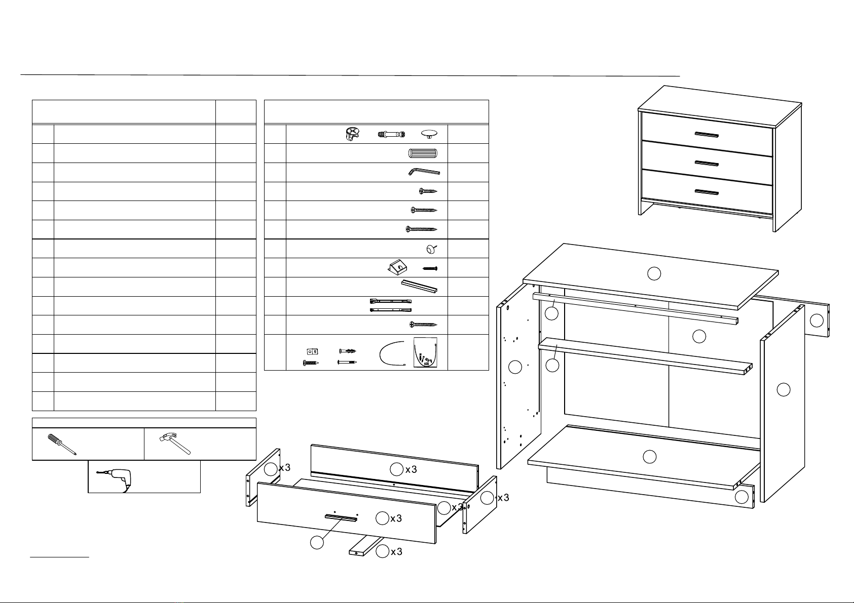
PART LIST
TOP PANEL MINI FIX
4
SIDE PANEL (L)
6
SIDE PANEL (R)
7
8
QTY
3
5
HARDWARE
A
B
C
D
E
F
G
26 SETS
ALLEN KEY M4 1 PC
BOTTOM PANEL
H
I
J
L
A1 A2 A3
M8 X 30MM WOOD DOWEL 20 PCS
9
10
M3.5 X 16MM C.B SCREW
6 PCS
12 PCS
42 PCS
SCREWDRIVER HAMMER
SELF-PREPARED TOOLS: Tools below are NOT included in package.
1 PC
1 PC
1 PC
1 PC
11
12
14
13
BOTTOM BONE
MIDDLE BONE
BACK BONE
BACK PANEL
DRAWER FRONT
DRAWER BACK
DRAWER SIDE (L)
DRAWER SIDE (R)
DRAWER BOTTOM
DRAWER BONE
1 PC
1 PC
1 PC
1 PC
3 PCS
3 PCS
3 PCS
3 PCS
6 PCS
M4 X 25MM C.B SCREW
M4 X 38MM C.B SCREW
5/8 PVC NAIL LEG
H1 H2 8 SETS
STUD 192 WITH SCREW
PVC HANDLE 7050.96 3 PCS
12" DRAWER SLIDE J1 ( L/R )
J2 ( L/R ) 3 SETS
TIPPING PACK WITHOUT AI
L1
L2
L3
L4 L5 2 SETS
1
2
3
4
5
6
7
8
9
1011
12
13
14
x 3
x 3
x 3
x 3
x 3
x 3
I
15 METAL SUPPORT 1 PC
M4 X 30MM C.B SCREW
K3 PCS
3 PCS
3 PCS
POWER DRILL
15
STEP 1 STEP 2
STEP 3 STEP 4
ASSEMBLY INSTRUCTIONS
6
2
7
11
12
14
3
1
9
10
15 3
4
5
6
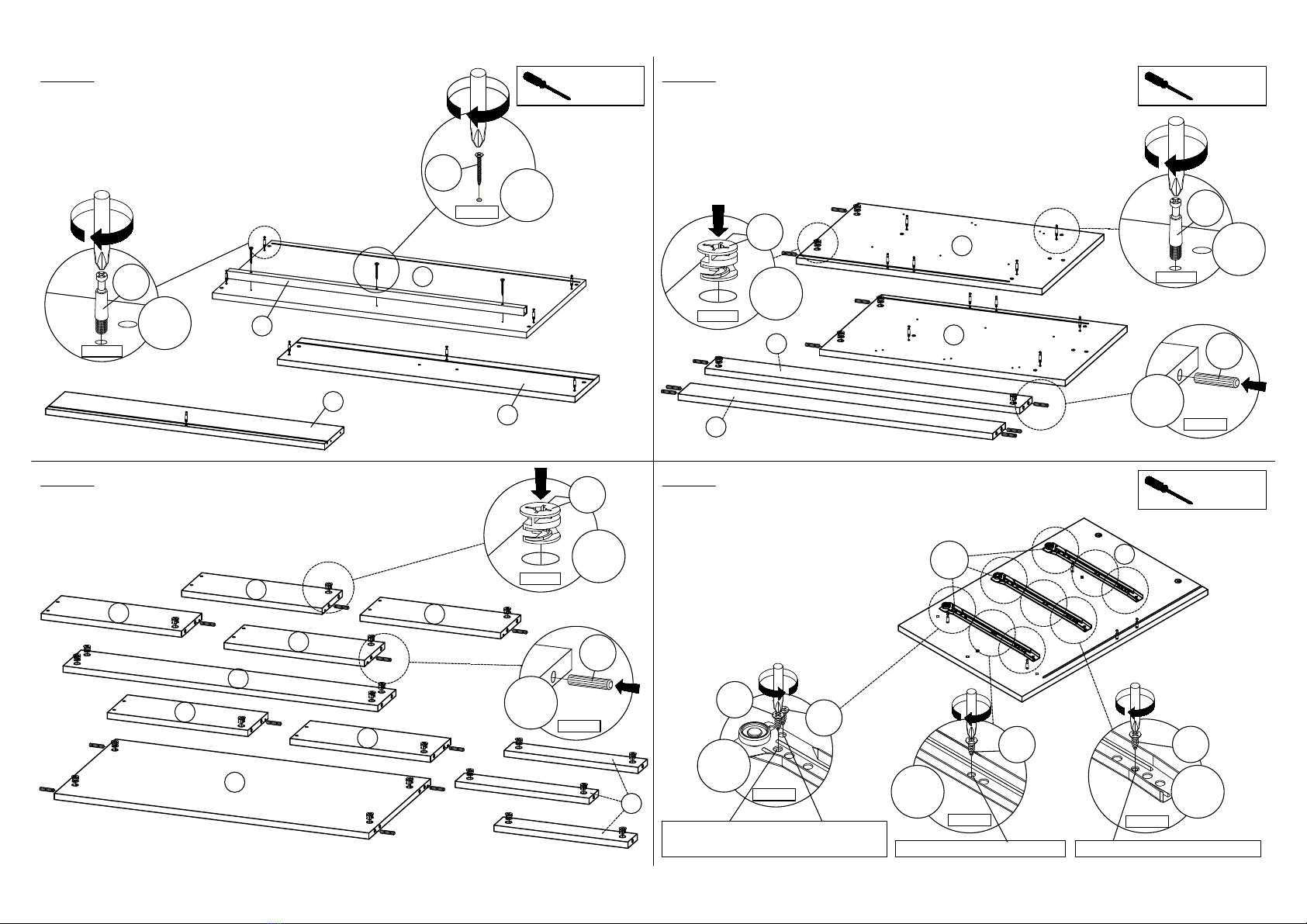
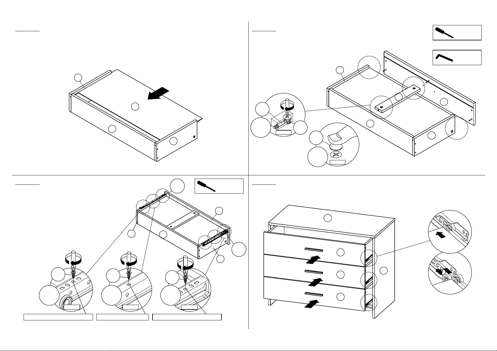
- Insert hardware A2 onto panel (1), (9) and (10).
(Repeat 16 times.)
- Connect Metal Support (15) to panel (1)
by using hardware K.
(Repeat 3 times.)
SCREWDRIVER
REQUIRED - Insert hardware A1 onto panel (3), (4) and (6).
(Repeat 6 times.)
- Insert hardware A2 onto panel (3) and (4).
(Repeat 10 times.)
- Insert hardware B onto panel (3), (4), (5) and (6).
(Repeat 10 times.)
SCREWDRIVER
REQUIRED
* Ensure the arrows on hardware A1 point towards mounting positions.
PRESS
A1
x6
PRESS
B
x10
A2
ROTATE
x10
- Insert hardware A1 onto panel (2), (7), (11), (12) and (14).
(Repeat 20 times.)
- Insert hardware B onto panel (2), (11) and (12).
(Repeat 10 times.)
* Ensure the arrows on hardware A1 point towards mounting positions.
Fix hardware J1 (L) into panel (3) with hardware D.
(Repeat 4 times for each hardware.)
SCREWDRIVER
REQUIRED
Third hole from the edge.
Small hole at the center.
x3 x3
ROTATE ROTATE
DD
J1(L)
A2
ROTATE
x16
12
12 11
11
PRESS
A1
x20
PRESS
B
x10
x6
ROTATE
D
D
First hole from the edge and
top second hole from the edge.
X 3 X 3
ROTATE
Kx3
STEP 5 STEP 6
STEP 7 STEP 8
ASSEMBLY INSTRUCTIONS
7
2
3
4
8
1
2
3
4
4
2
3
4
5
6
7
Fix hardware J1 (R) into panel (4) with hardware D.
(Repeat 4 times for each hardware.)
SCREWDRIVER
REQUIRED
x3x3
ROTATE
ROTATE
D
D
Third hole from the edge. Small hole at the center.
J1(R)
- Attach panel (3) and (4) to panel (2), (5), (6) and (7).
- Insert all hardware A2 into A1.
- Rotate all A1 until tight.
- Apply A3 onto all A1.
(Repeat 10 times.)
OR
HARDWARE
C
SCREWDRIVER
REQUIRED
* In this step hardware A1, A2 and B are pre-inserted.
PRESS
A3
x10
ROTATE
Section View
A2 A1
x10
Insert the panel (8) along the slot.
(Repeat 1 times.)
- Attach panel (1) to panel (3) and (4).
- Insert all hardware A2 into A1.
- Rotate all A1 until tight.
- Apply A3 onto all A1.
(Repeat 4 times.)
OR
HARDWARE
C
SCREWDRIVER
REQUIRED
* In this step hardware A1, A2 and B are pre-inserted.
ROTATE
Section View
x4
A2
A1
PRESS
A3
x4
x6
ROTATE
D
First hole from the edge and
top second hole from the edge.

STEP 9 STEP 10
STEP 11 STEP 12
ASSEMBLY INSTRUCTIONS
8
9
I
10
11
12
2
3
4
5
1
2
3
4
Hit hardware G into bottom of panel (3), (4) and (5).
(Repeat 6 times.)
HAMMER
REQUIRED - Insert hardware H1 into slot at panel (1), (2), (3) and (4).
- Assemble hardware H1 by using hardware H2.
(Repeat 8 times.)
SCREWDRIVER
REQUIRED
x8
H2
H1
ROTATE
Fix hardware I onto panel (9) by using hardware E.
(Repeat 2 times for each hardware.)
SCREWDRIVER
REQUIRED
ROTATE
Ex6
Assemble panel (10) to panel (11) and (12) by using hardware F.
(Repeat 12 times.)
* In this step only show one of the drawers.
x12
F
ROTATE
x6
HIT
G
9
I
9
I
X 3
X 3
X 3
STEP 13 STEP 14
STEP 15 STEP 16
ASSEMBLY INSTRUCTIONS
9
9
10
11
12
1
4
9
10
11
12
13
10
11
12
14 9
Insert the panel (13) along the slot.
(Repeat 3 times.)
* In this step only show one of the drawers.
Section View
ROTATE
A2
A1
PRESS
A3
x12
x12
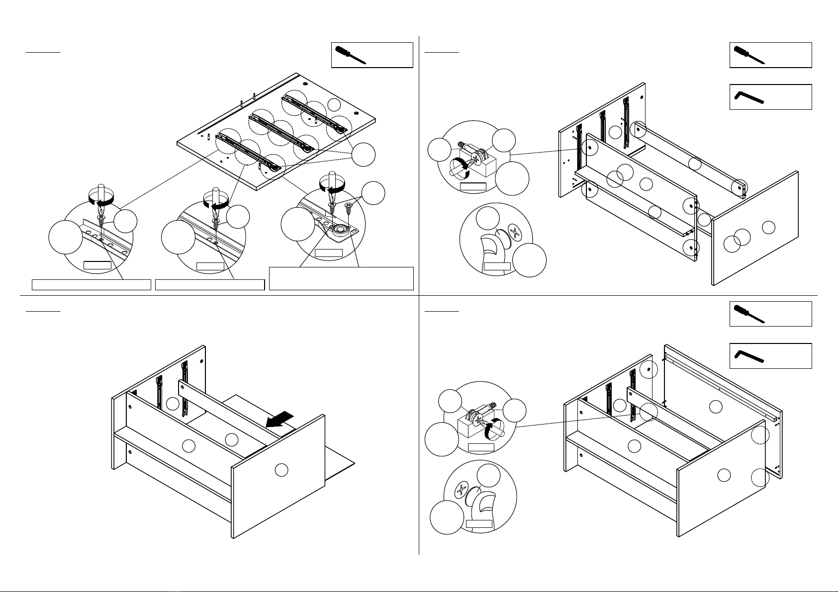
Assemble hardware J2 (L/R) to panel (11) and (12)
by using hardware D.
(Repeat 3 times for each hardware.)
* In this step only show
one of the drawers.
SCREWDRIVER
REQUIRED
x6
D
x6
D
x6
D
ROTATE ROTATE ROTATE
Hole at the center.
Third hole from the edge. Third hole from the edge.
*Hardware J2 (L/R) shall be leaning against panel (9) when assembling.
Put all the drawer in place along the drawer slides.
- Attach panel (14) to panel (10).
- Attach panel (9) to panel (11), (12) and (14).
- Insert all hardware A2 into A1.
- Rotate all A1 until tight.
- Apply A3 onto all A1.
(Repeat 12 times.)
* In this step only show one
of the drawers.
OR
HARDWARE
C
SCREWDRIVER
REQUIRED
* In this step hardware A1, A2 and B are pre-inserted.
J1(R)
J1(L)
9
9
X 3
X 3
X 3
X 3
X 3
X 3 X 3
X 3
X 3
X 3
X 3
X 3
X 3
STEP 17 STEP 18
STEP 19 STEP 20
ASSEMBLY INSTRUCTIONS
10
1
4
7
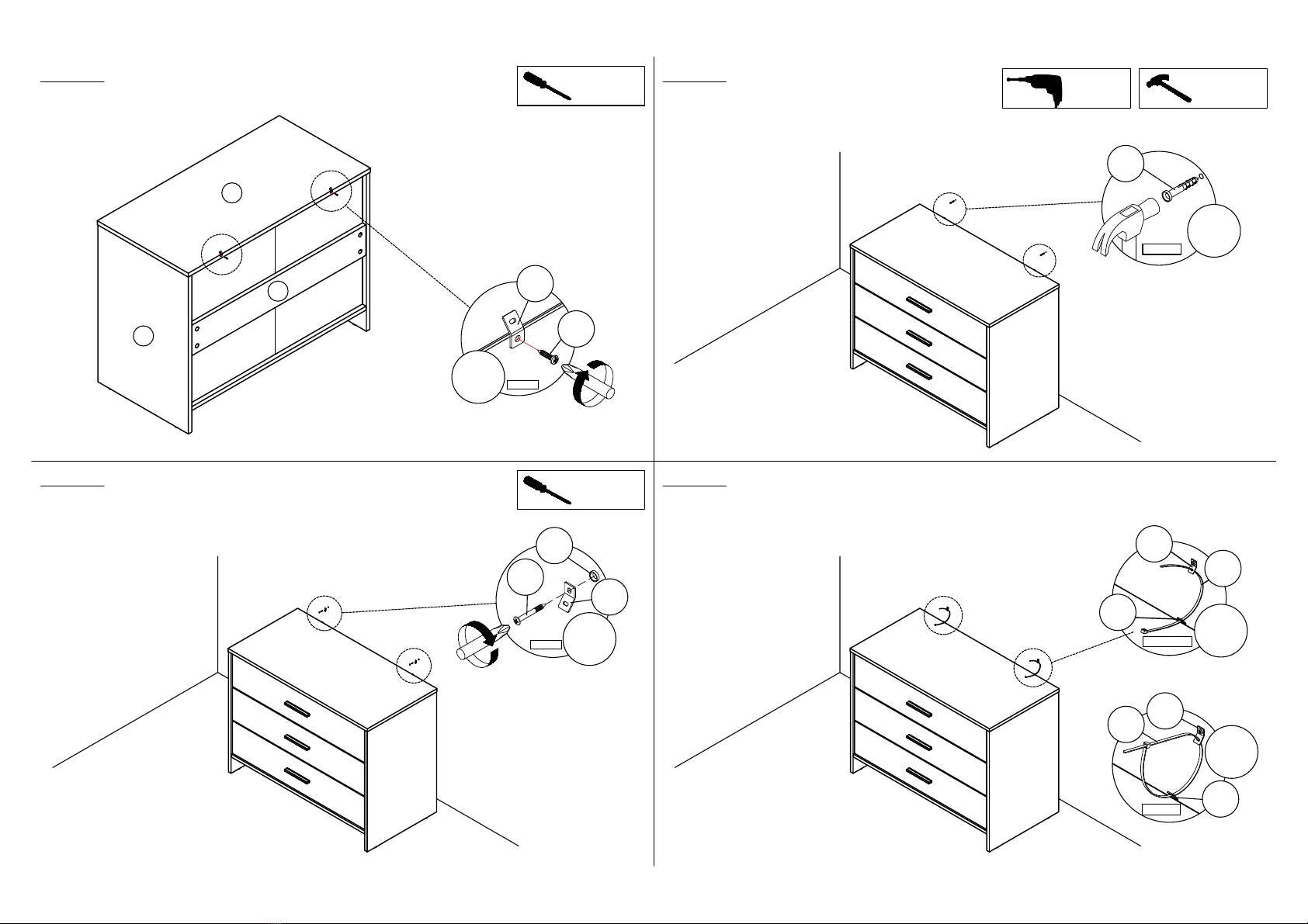
Assemble hardware L1 into panel (1)
by using hardware L2.
(Repeat 2 times.)
SCREWDRIVER
REQUIRED
ROTATE
x2
L1
L2
- Mark and use the power drill
to drill a hole on the wall.
- Hit hardware L3 into the wall.
(Repeat 2 times.)
HAMMER
REQUIRED
POWER
DRILL
REQUIRED
HIT
x2
L3
- Assemble hardware L1 to L3 by using hardware L4.
(Repeat 2 times.)
SCREWDRIVER
REQUIRED
ROTATE x2
L1
L3
L4
- Connect both of the hardware L1 by using hardware L5.
- Tighten the hardware L5.
(Repeat 2 times.)
TIGHTEN
CONNECT x2
L1
L1
L5
x2
L1
L1
L5
* Maximum recommended weight is 10kg on top and 8kg per drawer.

Warranty returns
Should you for any reason need to return this product for a warranty
claim, make sure to include all accessories with the product.
Product does not work?
If you encounter problems with this product, or if it fails to perform to
your expectations, make sure to contact our After Sales Support Centre
on (AU) 1300 886 649 or (NZ) 0800 836 761 for advice.
For an electronic copy of this manual, please contact our after sales support centre.
Distributed by Tempo (Aust) Pty Ltd ABN 70 106 100 252
PO BOX 132, Frenchs Forest NSW 1640, Australia
Customer Helpline:
(AU) 1300 886 649 (NZ) 0800 836 761
Web Support: tempo.org/support
IM Version No: V1.0 Issue: August 2022
11
Table of contents
Other Ostro Furniture Indoor Furnishing manuals


Popular Indoor Furnishing manuals by other brands

Regency
Regency LWMS3015 Assembly instructions

Furniture of America
Furniture of America CM7751C Assembly instructions

Safavieh Furniture
Safavieh Furniture Estella CNS5731 manual

PLACES OF STYLE
PLACES OF STYLE Ovalfuss Assembly instruction

Trasman
Trasman 1138 Bo1 Assembly manual

Costway
Costway JV10856 manual


