OT Bioelettronica Quattro User manual

User Manual v 1.3
quattro
Portable bioelectrical signal amplifier
Read this manual carefully before using quattro

quattro user manual v1.3 - November 2017
2

quattro user manual v1.3 - November 2017
3
Index
1 GENERAL DESCRIPTION .........................................................................................................................5
2 QUATTRO KIT CONTENT.......................................................................................................................... 6
3 END USER ................................................................................................................................................6
3.1 CONTRAINDICATIONS........................................................................................................................................ 6
3.2 SIDE EFFECTS ................................................................................................................................................ 6
4 SAFETY CAUTIONS AND OTHER WARNINGS .......................................................................................... 7
5 SYMBOLS USED ON QUATTRO AND IN THE USER MANUAL ................................................................... 8
6 TECHNICAL SPECIFICATIONS................................................................................................................. 9
7 DETAILED DESCRIPTION ......................................................................................................................11
7.1 CONTROLS,INDICATORS AND CONNECTOR............................................................................................................ 11
7.1.1 INPUT CONNECTORS....................................................................................................................................... 12
7.1.2 ON/OFF SWITCH .......................................................................................................................................... 12
7.1.3 USB MINIBCONNECTOR ................................................................................................................................. 12
7.1.4 LEDS INDICATORS ......................................................................................................................................... 13
7.1.5 ANALOG OUT CONNECTOR ............................................................................................................................... 14
8 USE OF QUATTRO ..................................................................................................................................15
8.1 QUATTRO DIGITAL INTERFACE........................................................................................................................... 15
8.2 SIGNALS ..................................................................................................................................................... 16
8.3 ELECTRODE ADAPTERS .................................................................................................................................... 16
8.4 PATIENT CONNECTION .................................................................................................................................... 18
9 TROUBLESHOOTING..............................................................................................................................19
10 QUATTRO MAINTENANCE AND STORAGE.............................................................................................20
11 TECHNICAL CHARACTERISTICS............................................................................................................21

quattro user manual v1.3 - November 2017
4
12 WARRANTY ............................................................................................................................................22
12.1 WARRANTY CONDITIONS ................................................................................................................................. 22

quattro user manual v1.3 - November 2017
5
1GENERAL DESCRIPTION
The quattro is a four-channel amplifier for surface electromyographic (sEMG) signals detected from skeletal muscles with the use
of the surface electrodes.
The quattro allows the detection and recording of the electric signals generated by human body. The signals acquired by the
instrument are amplified, filtered, digitally converted and then transferred to a PC, through Bluetooth or USB connection, for real-
time visualization and storage. A freeware software for real time display and storage, called OT BioLab, has been designed by OT
Bioelettronica and is available for download on the website www.otbioelettronica.it, under the download page.
The quattro is a research instrument designed for clinical research carried out by qualified researchers. It is completely safe for
the patient. The safety is achieved by satisfying the design requirement for devices with an electronic part applied to the patient.
Quattro has different adapters for the connection to different electrode types.

quattro user manual v1.3 - November 2017
6
2QUATTRO KIT CONTENT
•1 portable four-channel amplifier quattro;
•cable adapters to connect electrodes to the
amplifier, depending on the customer request;
•1 reference straps for the wrist;
•1 USB cable type A-MiniB;
•Electrodes of different sizes, depending on the
customer request;
•1 quattro user manual.
3END USER
Quattro allows non-invasive recording sEMG detected by superficial electrodes. The end user must be familiar with the technique
and received a proper training in EMG detection and interpretation.
3.1 Contraindications
Quattro has no particular contraindications when used jointly with personal computers, provided that all the electrical devices
connected to it comply with safety rules and standards concerning grounding and leakage currents.
3.2 Side effects
No significant side effects are known. The materials used for manufacturing all the parts in contact with the patient are
biocompatible. Possible slight cutaneous allergic reactions (e.g. skin reddening) are reduced to a minimum during short duration
of bioelectrical signal acquisitions.

quattro user manual v1.3 - November 2017
7
4SAFETY CAUTIONS AND OTHER WARNINGS
The use of the multichannel amplifier quattro is absolutely forbidden in the following conditions:
•While other monitoring devices are in use with the patient.
•While electro surgery equipment, short waves or microwaves therapy devices are used.
•By mentally impaired people.
•Whenever the equipment is damaged.
•In proximity of inflammable substances (especially inflammable liquids and gases) or in environments with high concentration
of oxygen.
•On patients carrying life-supporting equipment that might be adversely affected by electromagnetic interferences, such as
pacemakers, etc.
The following cautions should be observed:
•Only use electrodes supplied by the manufacturer: quattro is guaranteed to achieve tested performance only if used with
electrodes supplied by the manufacturer.
•Contact the manufacturer immediately if extraneous materials permeate into the device (liquids, powders, etc.). In case of
hard shocks suffered by the quattro (like a drop to the floor, etc.), verify that no crack or any other kind of damage of the
box resulted from the shock. In case of doubt, please contact the manufacturer.
•The quattro is subject to electromagnetic interference that is not dangerous for the patient (such as electrostatic or
electromagnetic interference generated by electrical motors and other sources). This interference may affect the
measurements of the physiological variables derived from the EMG or EEG signals. These measurements are not meant to
be used for diagnostic purposes, and thus these signal alterations cannot be dangerous for the patient, please always take
into account the presence of noise in your signal processing tasks and evaluations.
quattro user manual v1.3 - November 2017
8
•The connection between quattro and other electrical devices must be done in compliance with the European standard EN
60601-1-1 on medical devices.
•The use of the quattro is restricted to skilled personnel.
•Incorrect measurements can arise when unskilled personnel use the device in presence of strong sources electromagnetic
interference (e.g. strong electromagnetic fields). The presence of interference in the signals is easily recognised by skilled
personnel.
5SYMBOLS USED ON QUATTRO AND IN THE USER MANUAL
Class BF for circuitry applied to patient.
Read carefully the instruction remarks before use.
Signals input.

quattro user manual v1.3 - November 2017
9
6TECHNICAL SPECIFICATIONS
Quattro is a battery powered and galvanically insulated device designed to guarantee a high safety level for the patient and the
operator in all operating conditions. The galvanic insulation separates the circuitry connected to the patient from the circuitry
connected to external non-medical devices, such as the PC used for data acquisition. Moreover, when using the Bluetooth
communication, the insulation is intrinsically achieved by the wireless data transfer.
The connection with external devices must be done in compliance with the European standard EN 60601-1-1 on medical devices.
Table 6.1 shows the list of available adapters. Each of them allows the connection with different type of electrodes. One of the
four possible adapter, provided in the quattro kit, differs from the others because of an additional connection for the patient
reference. All of them are active differential adapters with a gain of 5V/V and no filters, making directly the difference between
the signals detected from the electrode pair inside the adapter.
Adapter
Description
Electrode example
ADx5JB
Active differential adapter with 1.5 mm banana connectors
ADx5JC
Active differential adapter with concentric connectors
ADx5JS
Active differential adapter with snap-on connectors
TAB. 6.1: list of quattro available adapters
quattro user manual v1.3 - November 2017
10
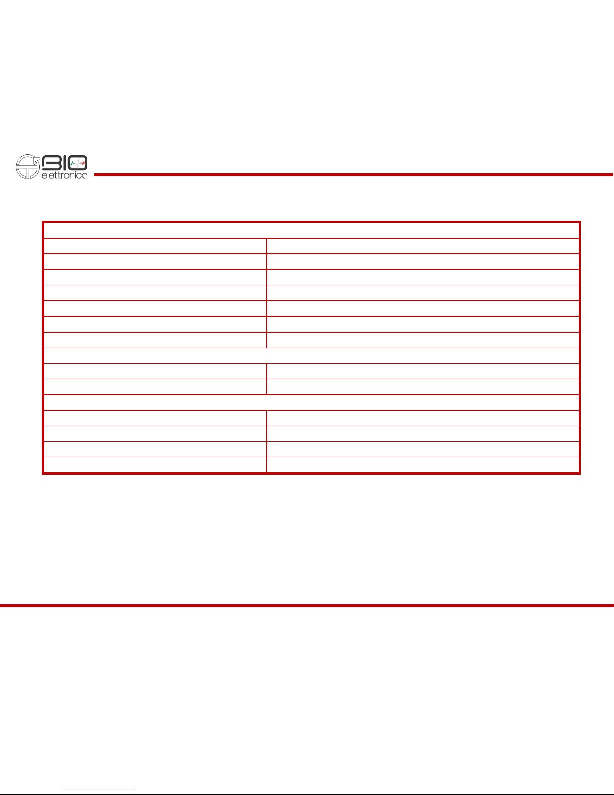
Quattro technical specifications are shown in Table 6.2.
EMG channels
Number of channels
4
Gain
150 V/V
Low pass filter
500 Hz
High pass filter
10 Hz
Noise level referred to input
< 2 VRMS
Input resistance
> 109
Input range
± 11 mV
Analog Outputs
Number of outputs
4
Output dynamics
0 –5 V
Data conversion and communication
A/D converter resolution
16 bits
A/D converter input dynamics
± 2.5 V
Sample frequency
1024 Hz
Data transfer to PC
USB cable or Bluetooth
TAB. 6.2: quattro technical specification

quattro user manual v1.3 - November 2017
11
7DETAILED DESCRIPTION
Quattro is a battery portable equipment for acquisition of surface EMG. Signals can be transferred to a PC, tablet or smartphone
for real time display and recording or for generation of real-time feedbacks to the patient.
Data transfer to a PC is obtained through a USB connection or Bluetooth communication. A configuration string sent to quattro
can set all the acquisition parameters and start the data transfer. The communication protocol is available for custom development
together with demonstration Matlab code. Some demonstrative apps for Android are also available.
7.1 Controls, indicators and connector
Controls, indicators and connector are highlighted in figure 7.1 and described in the subsequent sections.
FIG. 7.1: Quattro controls, connectors and indicators
quattro user manual v1.3 - November 2017
12
7.1.1 Input connectors
The four 4-pole 2.5 mm jack connectors are the interface between quattro and the active adapters. These connectors provide
power supply to the preamplifier and get back the differential signals amplified with a gain of 5.
The different adapters allow to connect the device with different type of electrodes and sensors. The connectors pinout is available
on request for custom developments. Refer to section 8.3 for additional details about the available adapters.
A good procedure is to connect the adapters to the input jacks of quattro when the device is off. No risk for the patient or for the
device are known when connecting and removing the adapter and the quattro is on, but big artefact are associated to the
connection and disconnection of the adapters on all four channels.
One of the four adapter differs from the other because of an additional wire terminated with a snap-on connector. This connection
is the Patient reference that is used to fix the common patient common mode to the mid-poin of the quattro power supply. Refer
to section 8.4 for details about the patient connection.
7.1.2 ON/OFF switch
This switch turns on and off the quattro by completely remove the battery supply from all its parts. Always move the switch in the
OFF position when the device is not used to avoid battery discharge.
7.1.3 USB MiniB connector
This USB port has a double function for battery recharging and data transfer between quattro and a PC. When connected to a PC
this port is seen as a Virtual COM. When quattro is used in combination with OT BioLab there is no need to install drivers or
configuring anything. For custom development, drivers are available for all major operative systems (Windows, Windows CE,
Linux, Mac OS) on the web page www.ftdichip.com/Drivers/VCP.htm.
Please contact OT Bioelettronica to get all the necessary information about drivers and communication protocol to communicate
with quattro in a custom scenario. Matlab codes are also available as guideline for direct communication with quattro.

quattro user manual v1.3 - November 2017
13
The supply for battery charging can be provided with any USB A-MiniB cable connected to a PC or to a wall DC adapter, like the
ones used for any smartphone. When connected to a PC, please check the PC power supply setting to ensure that it won’t enter
the standby mode during the recharge and interrupting it. The
Recharge
red LED beside the USB port indicates, when it is on,
that the battery recharge is in progress and, when it turns off, that the recharge is completed.
The integrated circuit that controls the battery recharge implement different recharge technique depending on the battery level:
battery conditioning, constant current and constant voltage. The constant current phase is the one that last longer and produce
a more efficient battery recharge. The recharge current is internally set to about 210 mA. A complete charge can require several
hours, since the internal battery has a capacity of 1600 mAh. The recharge can occur even when the patient is connected to
quattro thanks to an internal insulation circuit that guarantee an insulation of 4000 V between the part applied to the patient and
the recharge source.
7.1.4 LEDs indicators
The three LEDs are used to identify the state of quattro. Each of them reflect the state of a different activity of the device:
-The
Recharge
red LED indicates that the quattro is charging the internal battery. Refer to section 7.1.3 for details about
battery charging.
-The
Status
blue LED reports the Bluetooth state. It blinks when the Bluetooth is not connected with any device and switch
on when a connection is established.
-The
Battery/Error
red LED highlights low battery level or data transfer error. In particular, it is turned on when the battery
level goes under the threshold of 20% and, during the communication, is turned on if the internal buffer of quattro is full.
This can happen when data cannot be send out though USB or Bluetooth, for example because the quattro is too far from
the receiving device.
quattro user manual v1.3 - November 2017
14
7.1.5 Analog Out connector
The four EMG signals amplified and filtered from quattro are also available on this output connector. The signals are internally
sampled for the data transfer to USB or Bluetooth. The digitalized data cross the insulation barrier and is then converted back to
analog signals by means of an internal D/A converter. The internal sampling frequency is set to 10 kHz when data transfer on
USB or Bluetooth is not active and is 1024 Hz (the same used for data acquisition) when the one of the two communication is
active.
The voltage range at this connector is 0 to 5V, with the mid-point used as reference for the analog signals that can swing between
± 2.5V with respect to the reference. The default gain factor is 150V/V but an internal multiplication factor of 2, 4 or 8 can be
added by sending specific commands to quattro.
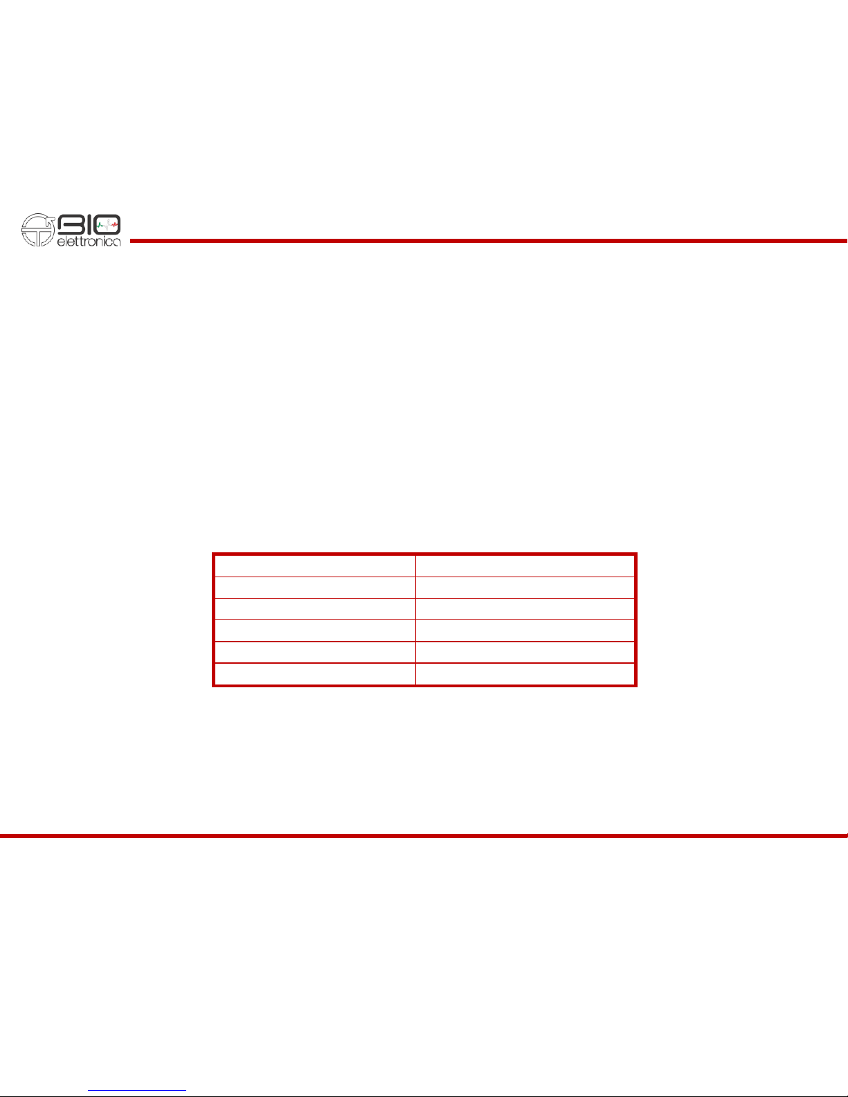
The connector used for the Analog output is a female 5-pin connector produced by Binder with part number 09 9792 30 05, the
pinout is reported in table 7.1. Accessory cable that split this output to 4 BNC connector is available.
Pin n.
Signal
1
Ch1 Out
2
Ch2 Out
3
Ch3 Out
4
Ch4 Out
5
GND
TAB. 7.1: pinout of the analog output connector

quattro user manual v1.3 - November 2017
15
8USE OF QUATTRO
The quattro can be interfaced to any device with a USB port or a Bluetooth interface and running any kind of operative system.
This manual refers to the use of quattro together with PC with Windows and the freeware software OT BioLab. In case a different
type of operative system is used, or if the user interface needs to be customized, the configuration and communication protocol
of quattro is available, as Matlab examples. Please contact OT Bioelettronica to receive the additional manual and examples.
8.1 Quattro digital interface
Quattro can transfer data to OT BioLab for real-time data display and storage through the USB port or the Bluetooth interface.
Only one interface is available at a time.
USB Interface
USB drivers for quattro are pre-installed during the installation of OT BioLab. On the first connection between the PC and quattro
the installation will be completed automatically and a Virtual COM number will be associated to the quattro. OT BioLab will be able
to automatically recognize the right COM port and start the communication with quattro without the need to set any particular
parameter. Refer to OT BioLab manual for details about the real-time data display and recording.
Bluetooth Interface
To use the Bluetooth interface, it is first of all necessary to pair a PC (with OT BioLab installed) to the quattro. The pairing process
is a standard process for Bluetooth devices that require a manual intervention to give consent at the interface between two
particular devices. For additional details about Bluetooth pairing, refer to available literature about Bluetooth or search for one of
our tutorial video on the www.otbioelettronica.it website. After the pairing has been completed, using OT BioLab and selecting
the Bluetooth option, the communication with quattro can be established and the data can be transferred to the PC in real-time.
Few Android Apps are also available for smartphones and tablets. Quattro can be used jointly with these Apps to provide the

quattro user manual v1.3 - November 2017
16
patient with a muscle contraction real-time feedback. Few apps have been developed as videogame where the contraction level
controls videogame instead the joypad or the keyboard.
8.2 Signals
The resolution of quattro is 16 bits obtained by sampling the signals with a SAR A/D converter. The amplification chain has the
first stage in the adapter, few cm apart the electrodes, allowing the reduction of interferences to the minimum. The other stages
into the quattro allow to amplify and filter the EMG signals with a fixed gain of 150 V/V and bandwidth between 10 Hz and 500
Hz (filters respectively of the second and fifth order). An additional circuit on the first stages of the amplification chain has been
designed for the reduction of artefact during electrically elicited contractions.
A single A/D converter with multiplexed inputs is used for all 4 channels. This introduce a small delay in the order of 20 µs between
the sampling of one channels and the next one. This error is negligible for any kind of processing applied on the EMG signals. The
A/D converter input dynamic is 0 ÷ 5 V, considering the amplification gain this reflect a resolution referred to the input equal to:
LSBRTI = ADCRANGE/Gain/216 = 508.6 nV
That is absolutely lower than the intrinsic noise generated by the electrode-skin contact, allowing the detection of the smallest
possible EMG activity.
The unused channels, if the adapter is not connected, have the inputs connected to the reference that force the signals to be flat
and equal to zero, avoiding any disturb on the active channels.
8.3 Electrode adapters
Each adapter is intended for the connection to a particular electrodes type. All of them are active and have a differential stage in
the small box close to the electrode with a gain of 5 V/V. No filters are implemented in the adapters. It is recommended to connect
the adapter to the quattro when the quattro is off, avoiding artefact on all channels during the connector insertion or removal.
In the set of adapters provided, one of them has an additional connection for the patient reference. This adapter must always be
used when acquiring EMG signals and the patient reference connection applied to the patient body.

quattro user manual v1.3 - November 2017
17
ADx5JB
This adapter allows the connection of electrode with 1.5 touchproof banana connectors. Figure 8.1 shows the adapter.
FIG. 8.1: The ADx5JB adapter
ADx5JC
This adapter allows the connection of electrode concentric connectors. Figure 8.2 shows the adapter.
FIG. 8.2: The ADx5JC adapter
ADx5JS
This adapter allows the connection of electrode with snap-on connectors. Figure 8.3 shows the adapter.
FIG. 8.3: The ADx5JS adapter

quattro user manual v1.3 - November 2017
18
8.4 Patient connection
Regardless of the adapter used, in every quattro kit, one adapter has an additional connection terminated with a snap-on
connector. This connection is used to fix the common mode body potential of the patient to the midpoint of quattro power supply.
The skin-electrode impedance of this connection must be as low as possible, for this reason a large electrode is suggested (a
wetted reference strap is often a good choice) and have to be placed in a point without EMG activity. Typically, wrist, ankle or
over a bone. If this connection is missing, or the impedance too high, interferences can occur in all the EMG channels and the
signals can be strongly compromised.
Each channel is differential and amplifies the difference between two electrodes. The electrode choice depends on many factors
like the investigated muscles, the motor task, the need to avoid crosstalk from adjacent muscles, etc… Many books are available
to define the optimal condition for EMG recording, and different studies has been carried out demonstrating the repeatability of
particular variables extracted from bipolar EMG signals. Refer to the available scientific literature for further details about EMG
recording and interpretation.
There is no risk for the patient if the device has the USB connected to a power source and the battery are charging during the
measurements. The internal insulation between the part applied to the patient and other devices guarantee the patient safety in
every condition

quattro user manual v1.3 - November 2017
19
9TROUBLESHOOTING
This section describes the most common problems that may be found by quattro users, with some suggestions to solve them. For
problems not described in this section contact the technical support service of OT Bioelettronica.
GENERAL PROBLEMS
Problem
Possible cause
Solution
The quattro does not turn on
The battery level is too low
Let the device in charge for at least one hour
The device is not recognized by
Windows
A problem occurs during driver
installation
Install manually the drivers. They can be found in the
OT BioLab installation folder, under “driver”
When using in OT BioLab and
the Bluetooth checkbox is
checked, an error occurs
The quattro is not paired
Under
Windows Bluetooth Manager
you need to pair
the quattro with the computer
Windows Bluetooth Manager
does not exist on the computer
The PC has no Bluetooth interface
Add a USB Bluetooth dongle to your PC
TAB. 9.1:Troubleshooting of the general problem that can occur using the quattro

quattro user manual v1.3 - November 2017
20
10 QUATTRO MAINTENANCE AND STORAGE
Quattro has to be used in the following ambient conditions:
Temperature: from 0°C to +40°C
Maximum relative humidity: 75%
Atmospheric pressure: from 700 hPa to 1060 hPa
It is recommended to turn off the quattro at the end of each measurement session, and to remove all the cables and connections.
The quattro should be stored with all the enclosed accessories on a safe desk far from all the situations listed in the section
Warnings.
Quattro should be stored in the following ambient conditions:
Temperature: from –20°C to +40°C
Maximum relative humidity: 75%
Atmospheric pressure: from 700 hPa to 1060 hPa
Cleaning:use only a dry cloth to clean the device.
It is recommended to plan a device check every 24 months with the manufacturer. The quattro should be repaired by the
manufacturer only. Every repair executed by unauthorized personnel will be considered as a device violation voids the
manufacturer’s warranty.
Disposal
The device and the accessories should be disposed in compliance with the relative standards in special equipped areas or with
special waste.
Other manuals for Quattro
1
Table of contents
Other OT Bioelettronica Amplifier manuals

OT Bioelettronica
OT Bioelettronica Sessantaquattro+ User manual

OT Bioelettronica
OT Bioelettronica NOD User manual

OT Bioelettronica
OT Bioelettronica OT-BridgeAmp4 User manual

OT Bioelettronica
OT Bioelettronica GPA4 User manual

OT Bioelettronica
OT Bioelettronica EMG-USB2 User manual

OT Bioelettronica
OT Bioelettronica FORZA User manual


