OT Bioelettronica GPA4 User manual

GPA4
4 channels general purpose amplifier
User Manual

GPA4 User manual v 1.2
pag. 2
INDEX
1. GENERAL FEATURES....................................................................... pag. 3
1.1. GENERAL DESCRIPTION
.............................................. pag. 3
1.2. TECHNICAL SPECIFICATION
......................................... pag. 3
2. DETAILED DESCRIPTION ............................................................. pag. 4
2.1. FRONT PANEL
................................................................. pag. 4
Input BNC .......................................................................... pag. 5
INPUT switch ..................................................................... pag. 5
OFFSET switch ................................................................... pag. 5
POWER ON indicator........................................................... pag. 5
Output BNC........................................................................ pag. 5
OFFSET compensation potentiometer .................................. pag. 5
HIGH PASS FILTER selector ................................................ pag. 6
GAIN selector ..................................................................... pag. 6
LOW PASS FILTER selector ................................................. pag. 6
2.2. BACK PANEL
.................................................................... pag. 7
Power supply socket ........................................................... pag. 7
Power supply switch ........................................................... pag. 7
Fuse box............................................................................ pag. 8

GPA4 User manual v 1.2
pag. 3
1. GENERAL FEATURES
1.1. GENERAL DESCRIPTION
The GPA4 is a four channel general purpose amplifier. It can amplify and filters any
referenced single ended signal (i.e. signal referred to ground).
The four channels are completely independent and can be used simultaneously.
1.1. TECHNICAL SPECIFICATION
The GPA4 is a programmable amplifier with selectable high pass filter, low pass filter, gain
and offset compensation.
The GPA4 technical specifications are reported in Table 1.
Selectable High pass filter
DC coupled
1 Hz (II order)
10 Hz (II order)
Selectable Low pass filter
25 Hz (VIII order)
40 Hz (VIII order)
100 Hz (VIII order)
500 Hz (VIII order)
Selectable Gains
1, 2, 5, 10, 20, 50, 100, 200, 500, 1k, 2k, 5k V/V
Gain error
< 5 %
Input resistance
> 1012
Input range
4 V
Output range
4 V
Output offset
< 5 mV
Offset compensation
6.5 V, when DC coupled
TAB. 1: Amplifier technical specification
GPA4 User manual v 1.2
pag. 4
2. DETAILED DESCRIPTION
2.1.
FRONT PANEL
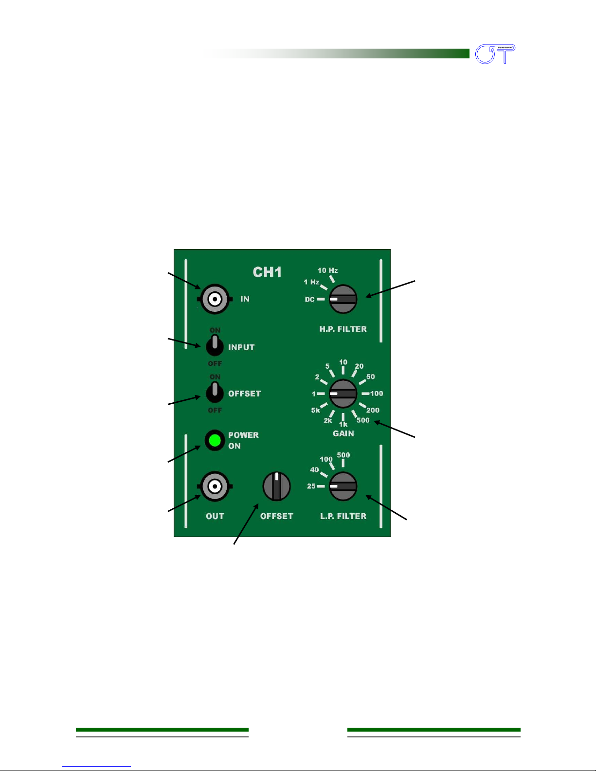
Figure 1 shows connectors switches and selectors of the GPA4. The four channels are
separated by vertical lines and the corresponding channel number is reported in the upper
part of the front panel.
Any indication reported in the following description can be associated to any GPA4 channel
exept when expressly indicated.
FIG. 1: Detail of GPA4 front panel reporting the firs channel
Input
BNC
Output
BNC
POWER
ON
indicator
OFFSET
switch
INPUT
switch
OFFSET
compensation
potentiometer
Low pass filter
selector
Gain selector
Low pass filter
selector

GPA4 User manual v 1.2
pag. 5
Input BNC
This connector is the input for the corresponding amplifier channel.
INPUT switch
This switch can be used to turn on or off the amplifier input. When the switch is in the ON
position the signal present at the BNC input is the input for the corresponding amplifier
channel. When the switch is in the OFF position the input of the corresponding amplifier
channel is connected to ground and the BNC input is disconnected from the circuit and in
a floating condition.
The INPUT switch can be used to turn off the input and evaluate the offset amount
introduced by the internal offset compensation at the amplifier channel output.
It is suggested to turn off the unused inputs to reduce the coupling of external
interference to the instrument.
OFFSET switch
When the channel is DC coupled the offset compensation can be turned on or off using
this switch.
Note that this switch has no effects when the high pass filter is used.
POWER ON indicator
The indicator is a greed led that is on when the amplifier is powered. The indicator is
common for all channels when on indicate that all channels are on.
Output BNC
This connector is the output for the corresponding amplifier channel.
OFFSET compensation potentiometer
This multi-turn potentiometer controls the offset compensation. To activate the offset
compensation the channel have to be DC coupled (refer to LOW PASS FILTER selector)
and the OFFSET switch have to be placed in the ON position.
Note that the offset is multiplied by the gain selected and the potentiometer sensitivity
increase with the gain.

GPA4 User manual v 1.2
pag. 6
The offset value, introduced by the offset compensation circuit, can be sent to the output
BNC and measured. The input signal has to be excluded by positioning the INPUT switch
in the OFF position and the channel gain has to be set equal to 1.
HIGH PASS FILTER selector
This three positions selector allows to select the -3 dB corner frequency of the second
order high pass filter. The DC position indicates that no high pass filters are introduced
and the channel is DC coupled. Available frequencies are: 1 Hz and 10 Hz.
The frequency values are theoretical, refer to the “Modulo di collaudo” for the real values.
GAIN selector
This twelve positions selector allows to select the channel gain. Available gains are: 1, 2, 5,
10, 20, 50, 100, 200, 500, 1000, 2000, 5000.
The gain values are theoretical, refer to the “Modulo di collaudo” for the real values.
LOW PASS FILTER selector
This four positions selector allows to select the -3 dB corner frequency of the eighth order
low pass filter. Available frequencies are: 25 Hz, 40 Hz, 100 Hz and 500 Hz.
The frequency values are theoretical, refer to the “Modulo di collaudo” for the real values.
GPA4 User manual v 1.2
pag. 7
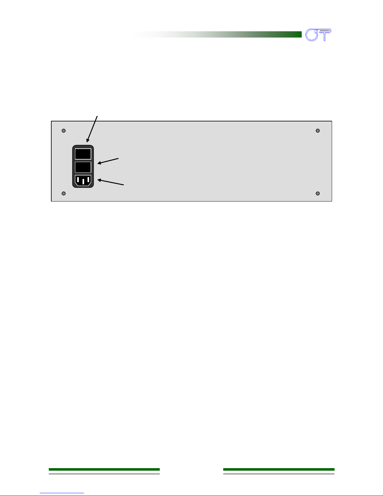
2.2. BACK PANEL
Fig. 2 shows the GPA4 back panel.
Power supply socket
Connect the power supply cable to this socket. The GPA4 system can be supplied with a
supply voltage ranging from 90 to 260 VAC, 50÷60 Hz; it is very important that the supply
cable includes the earth connector.
DANGER: The use of extension cords or multiple sockets or adaptors can affect the performance of the
instrumentation. The connection to sockets without earth connection or with a low quality earth
connection can affect the performance of the instrumentation and cause potential harm to operators.
Power supply switch
On the back panel, together with the power supply connector, the power supply switch
can be found. To switch the GPA4 on, move the power supply switch to position 1; to
switch it off, move it again to position 0. For higher safety, the switch interrupts
connection to both power conductors.
When the system is not used, this switch should be off.
0 1
Power supply
socket
Fuse box
Power supply
switch
FIG. 2:
Back panel of GPA4

GPA4 User manual v 1.2
pag. 8
Fuse box
On the back panel, together with the power supply connector, a box containing the two
power supply fuses (one for each cable) can be found. In normal working conditions the
two supply fuses must not be interrupted; the interruption of connection in either of them
can occur only when the system is damaged; this means that the device could no longer
be in compliance with the security standards, even if the fuses have been replaced
correctly.
DANGER: In case of interruption of one or both fuses, do not replace them by yourself, but immediately
contact the Technical Assistance Service of Ottino Bioelettronca.
Besides, replacing the fuses with others of different type can be dangerous. Always remove the power
cable before testing the fuses.

GPA4 User manual v 1.2
pag. 9
Produced and distributed by:
OT Bioelettronica
Via M. di Belfiore 25
10086 –Rivarolo C.se (TO) - ITALY
Tel:+39.0124.29897
Fax:+39.0124.26312
URL: www.ottinosnc.it
Table of contents
Other OT Bioelettronica Amplifier manuals

OT Bioelettronica
OT Bioelettronica EMG-USB2 User manual

OT Bioelettronica
OT Bioelettronica Quattro User manual

OT Bioelettronica
OT Bioelettronica Sessantaquattro+ User manual

OT Bioelettronica
OT Bioelettronica NOD User manual

OT Bioelettronica
OT Bioelettronica FORZA User manual

OT Bioelettronica
OT Bioelettronica OT-BridgeAmp4 User manual


