1. Introduction and Circuit Overview
AC100V –
120V
+ / 16V
Regulators
Transformer
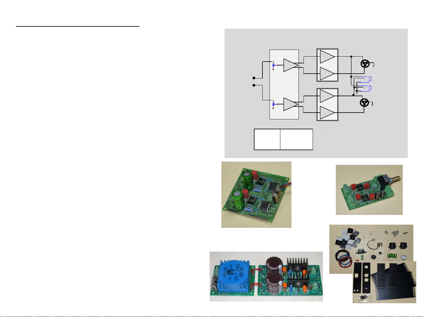
System Block Diagram
L-CH XLR output
R-CH XLR Output
RCA Input
L
R
Volume+
Balance
rive
circuit
1 ¼`` Jack
HOT
COLD
HOT
COLD
Left-CH
Right-CH
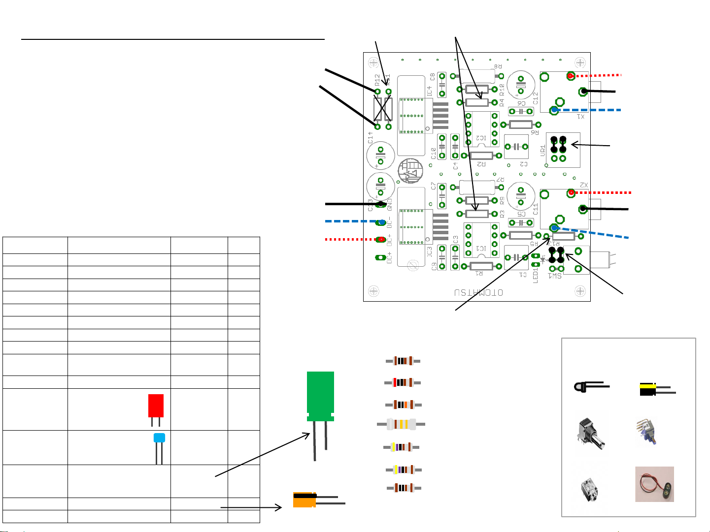
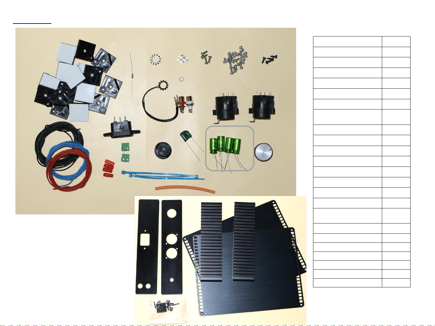
Total System configuration
- Headphone Amplifier Module x2
- Volume + Balance conversion module x1
- Power Supply Module + Transformer x1
- XLR Combo jack, Screw, Knob, Petet, Wire, AC inlet…etc set x1
- Case set x1
Transformer Regulators module Case set
Headphone Amplifier Modules x2
Volume + Balance drive Module
otomatsu
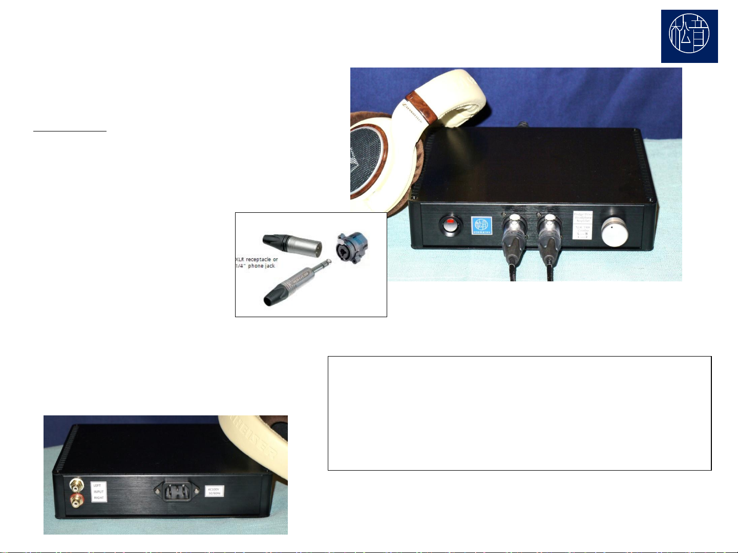
Balanced Headphone Amplifier kit , BDR-HPA1E
2
Rev.1.0E All Copy Right Reserved by otomatsu
The assembling of 2 sets of headphone amplifier module and adding a volume +
balance conversion circuit comprises a balance drive model headphone amplifier. For
a power supply circuit, we use a stabilization power supply kit to compliment an
exclusive compact, stylish case kit.
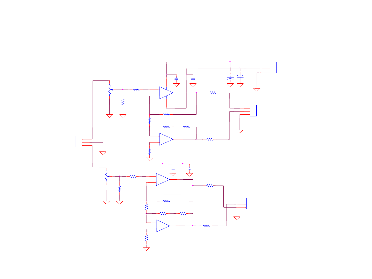
The line level signal that goes to the RCA jack enters the volume control of the
conductive plastic model which is made by TOKYO KO-ON DENPA Co. Ltd. Because
this volume control has fewer ganging errors, it balances the right and left volume
more efficiently.
The signal then enters an unbalanced-balanced conversion circuit that makes 2
distinct high and low contradistinction signals of +HOT and -COLD. This part uses an
OPAMP NE5532. It has 2 circuits and conducts precise, low noise and low distortion
rate signal conversion. In addition it has a DC amplifier setup so that the frequency
characteristic is flat from DC to 100 kHz
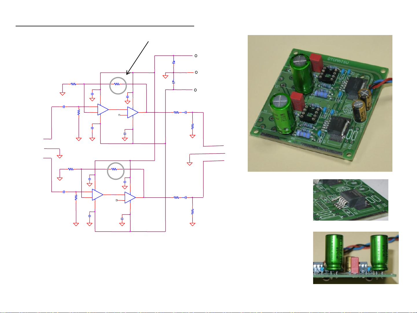
The signal then enters the headphone drive amplifier which amplifies the electric
power that drives the headphone. This part uses an OPAMP LME49710 with 1 circuit.
We triple this amplification in order to be able to supply enough electrical current to
the headphone impedance load between 16Ωand 300Ωin output buffer IC and
LME49600. By using WIMA’s film capacitor for the input, we cut the DC component
from the first part. Also for the output, it connects to the headphone jack through the
audio grade bipolar electrolysis capacitor of the low direct current equivalent
resistance and low leak current level not appearing on the DC component to the
headphone.
For the power supply circuit, we make the AC20V of 2 systems from 110V by using a
toroidal transformer and making the DC stabilize with low noise Schottky Barrier
diode and regulator IC LM317. It is a 2- system with a complete independent
stabilized rectification that keeps the ground level stabilized.
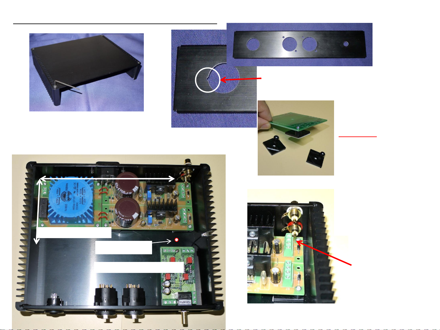
The headphone jack that is NEUTRIK brand supports both of XLR and standard stereo
phone jack. For the balanced headphone wiring, insert L to the left, R to the right. It
becomes perfectly balanced and is superior to LR channel separation. You can enjoy
full drive SN too. In addition, you can insert it into a regular stereo phone jack. When
you use a regular stereo phone jack, the same signals are made for both the right and
left jacks so you can operate 2 headphones simultaneously. More over, by using a XLR
balanced cable, you can operate a BLT power amplifier and use it as a balanced model
preamplifier.
In addition, it will be possible in the future to enhance the performance by replacing
OPAMP.