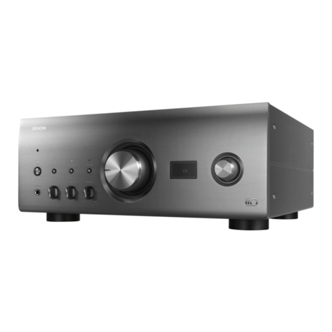
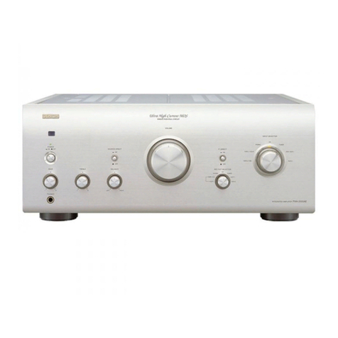
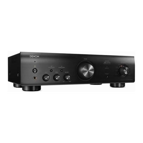
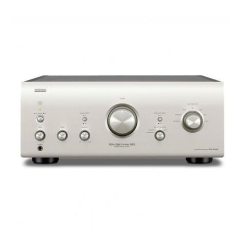
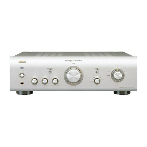
Denon PMA-2020AE User manual

D&M Holdings Inc.
SERVICE MANUAL
e
e
Copyright 2012 D&M Holdings Inc. All rights reserved.
WARNING: Violators will be prosecuted to the maximum extent possible.
MODEL JP E3 E2 EK EA E1C E1K EUT
PMA-2020AE
P P
INTEGRATED AMPLIFIER
Ver. 2
S0569-1V02DM/DG1210
• Some illustrations using in this service manual are slightly different from the actual set.
• Please use this service manual with referring to the operating instructions without fail.
• For purposes of improvement, specications and design are subject to change without notice.
Please refer to the
MODIFICATION NOTICE.

2
CONTENTS
ABOUT THIS MANUAL.............................................................3
What you can do with this manual ............................................3
Using Adobe Reader (Windows version) ..................................4
SAFETY PRECAUTIONS ..........................................................6
NOTE FOR SCHEMATIC DIAGRAM.........................................7
NOTE FOR PARTS LIST ...........................................................7
TECHNICAL SPECIFICATIONS................................................8
DIMENSION ...............................................................................8
DISASSEMBLY........................................................................11
1. REMOTE I/O UNIT..............................................................12
2. P.AMP(L) UNIT ....................................................................12
3. INPUT UNIT and PH/CD TER.UNIT....................................14
4. P.AMP(R) UNIT ...................................................................15
5. FRONT PANEL ASSY .........................................................16
6. BOTTOM COVER ...............................................................17
7. CE33W==123M...................................................................18
IDLING ADJUSTMENT............................................................19
TROUBLE SHOOTING............................................................20
1. The power can not be turned on.
(Power indication LED does not light.)
...................................20
2. The power turned on, but a sound
does not output normally. (Both channels) ..............................20
3. The power turned on, but a sound
does output normally. (Single channel) ...................................21
BLOCK AND LEVEL DIAGRAM .............................................22
WIRING DIAGRAM..................................................................23
PRINTED WIRING BOARDS...................................................24
SCHEMATIC DIAGRAMS (1/5) ...............................................29
110132_1.................................................................................29
110132_2.................................................................................30
110133_1.................................................................................31
110133_2.................................................................................32
110134_1.................................................................................33
EXPLODED VIEW....................................................................34
PARTS LIST OF EXPLODED VIEW........................................35
PACKING VIEW .......................................................................37
PARTS LIST OF PACKING & ACCESSORIES.......................37
SEMICONDUCTORS ...............................................................38
1. IC's ......................................................................................38
PARTS LIST OF P.C.B. UNIT ..................................................41
8U-110132 INPUT P.W.B. UNIT ASS'Y ..................................41
8U-110133 POWER AMP P.W.B. UNIT ASS'Y .......................45
8U-110134 FLAT AMP P.W.B. UNIT ASS'Y ............................48

3
Jump to the target of a schematic diagram
connector
Click the Ref. No. of the target connector in the red box
around a schematic diagram connector.
• The screen jumps to the target connector.
• Page magnification stays the same as before the
jump.
ABOUT THIS MANUAL
Read the following information before using the service manual.
What you can do with this manual
Search for a Ref. No. (phrase)
(Ctrl+Shift+F)
You can use the search function in Acrobat Reader to
search for a Ref. No. in schematic diagrams, printed
wiring board diagrams, block diagrams, and parts lists.
1.Press Ctrl+Shift+Fon the keyboard.
• The Search window appears.
Ctrl
Shift
F
2.Enter the Ref. No. you want to search for in the
Search window, and then click the Search button.
• A list of search results appears.
3.Click an item on the list.
• The screen jumps to the page for that item, and
the search phrase is displayed.

4
Using Adobe Reader (Windows version)
• Properties
Click this button and check that the printer is set to a
suitable paper size.
• Pagetoprint
Select the following checkbox.
"More Options" : "Current View"
• PageSizing&Handling
Select the following checkbox.
"Size" / "SizeOptions" : "Fit"
Add notes to this data (Sign)
The Sign function lets you add notes to the data in this
manual.
Save the le once you have nished adding notes.
[Example using Adobe Reader X]
On the "View" menu, click "Sign".
• The Sign pane appears.
[Example using Adobe Reader 9]
On the "Document" menu, click "Sign".
Magnify schematic / printed wiring board
diagrams - 1
(Ctrl+Space, mouse operation)
Press Ctrl+Space on the keyboard and drag the
mouse to select the area you want to view.
• The selected area is magnied.
Ctrl Space
0
• When you want to move the area shown, hold down
Space and drag the mouse.
• When you want to show a full page view, press
Ctrl+0on the keyboard.
Printamagniedpartofthemanual
The Properties dialog box and functions will vary depending on your printer.
1.Drag the mouse to magnify the part you want to print.
2.On the "File" menu, click "Print".
3. Congure the following settings in the Print dialog box.
4.Click the Print button to start printing.

5
Magnify schematic / printed wiring board
diagrams - 2
(Pan & Zoom function)
The Pan & Zoom function lets you see which part of a
magnied diagram is being shown in a separate window.
[Example using Adobe Reader X]
On the "View" menu, point to "Zoom", and then click
"Pan & Zoom".
• The Pan & Zoom window appears on the screen.
[Example using Adobe Reader 9]
On the "Tools" menu, point to "Select & Zoom", and
then click "Pan & Zoom Window".
Magnify schematic / printed wiring board
diagrams - 3
(Loupe Tool function)
The Loupe Tool function lets you magnify a specific
part of a diagram in a separate window.
[Example using Adobe Reader X]
On the "View" menu, point to "Zoom", and then click
"Loupe Tool".
• The Loupe Tool window appears on the screen.
[Example using Adobe Reader 9]
On the "Tools" menu, point to "Select & Zoom", and
then click "Loupe Tool Window".

6
SAFETY PRECAUTIONS
The following items should be checked for continued protection of the customer and the service technician.
LEAKAGE CURRENT CHECK
Before returning the set to the customer, be sure to carry out either (1) a leakage current check or (2) a line to chassis
resistance check. If the leakage current exceeds 0.5 milliamps, or if the resistance from chassis to either side of the
power cord is less than 460 kohms, the set is defective.
Be sure to test for leakage current with the AC plug in both polarities, in addition, when the set's power is in each state (on,
off and standby mode), if applicable.
CAUTION Please heed the following cautions and instructions during servicing and
inspection.
◎Heed the cautions!
Cautions which are delicate in particular for servicing
are labeled on the cabinets, the parts and the chassis,
etc. Be sure to heed these cautions and the cautions
described in the handling instructions.
◎Cautions concerning electric shock!
(1) An AC voltage is impressed on this set, so if
you touch internal metal parts when the set is
energized, you may get an electric shock. Avoid
getting an electric shock, by using an isolating
transformer and wearing gloves when servicing
while the set is energized, or by unplugging the
power cord when replacing parts, for example.
(2) There are high voltage parts inside. Handle with
extra care when the set is energized.
◎Caution concerning disassembly and
assembly!
Through great care is taken when parts were
manufactured from sheet metal, there may be burrs
on the edges of parts. The burrs could cause injury if
ngers are moved across them in some rare cases.
Wear gloves to protect your hands.
◎Use only designated parts!
The set's parts have specic safety properties (re
resistance, voltage resistance, etc.). Be sure to use
parts which have the same properties for replacement.
The burrs have the same properties. In particular, for
the important safety parts that are indicated by the z
mark on schematic diagrams and parts lists, be sure to
use the designated parts.
◎Be sure to mount parts and arrange the wires
as they were originally placed!
For safety seasons, some parts use tapes, tubes or
other insulating materials, and some parts are mounted
away from the surface of printed circuit boards.
Care is also taken with the positions of the wires by
arranging them and using clamps to keep them away
from heating and high voltage parts, so be sure to set
everything back as it was originally placed.
◎Make a safety check after servicing!
Check that all screws, parts and wires removed or
disconnected when servicing have been put back in
their original positions, check that no serviced parts
have deteriorate the area around. Then make an
insulation check on the external metal connectors and
between the blades of the power plug, and otherwise
check that safety is ensured.
(Insulation check procedure)
Unplug the power cord from the power outlet,
disconnect the antenna, plugs, etc., and on the power.
Using a 500V insulation resistance tester, check that
the insulation resistance value between the inplug and
the externally exposed metal parts (antenna terminal,
headphones terminal, input terminal, etc.) is 1MΩ or
greater. If it is less, the set must be inspected and
repaired.
Many of the electric and the structural parts used in
the set have special safety properties. In most cases
these properties are difcult to distinguish by sight, and
the use of replacement parts with higher ratings (rated
power and withstand voltage) does not necessarily
guarantee that safety performance will be preserved.
Parts with safety properties are indicated as shown
below on the wiring diagrams and the parts list in this
service manual. Be sure to replace them with the parts
which have the designated part number.
(1) Schematic diagrams.......Indicated by the z mark.
(2) Parts lists.......Indicated by the zmark.
The use of parts other than the
designated parts could cause electric
shocks, res or other dangerous
situations.
CAUTION Concerning important safety
parts

7
NOTE FOR SCHEMATIC DIAGRAM
WARNING:
Parts indicated by the z mark have critical characteristics. Use ONLY replacement parts recommended by the manufacturer.
CAUTION:
Before returning the set to the customer, be sure to carry out either (1) a leakage current check or (2) a line to chassis resistance check. If
the leakage current exceeds 0.5 milliamps, or if the resistance from chassis to either side of the power cord is less than 460 kohms, the set
is defective.
WARNING:
DO NOT return the set to the customer unless the problem is identied and remedied.
NOTICE:
ALL RESISTANCE VALUES IN OHM. k=1,000 OHM / M=1,000,000 OHM
ALL CAPACITANCE VALUES ARE EXPRESSED IN MICRO FARAD, UNLESS OTHERWISE INDICATED. P INDICATES MICRO-MICRO
FARAD. EACH VOLTAGE AND CURRENT ARE MEASURED AT NO SIGNAL INPUT CONDITION. CIRCUIT AND PARTS ARE SUBJECT
TO CHANGE WITHOUT PRIOR NOTICE.
NOTE FOR PARTS LIST
Parts indicated by "nsp" on this table cannot be supplied.
When ordering a part, make a clear distinction between "1" and "I" (i) to avoid mis-supplying.
A part ordered without specifying its part number can not be supplied.
General-purpose Carbon Chip Resistors are not included are not included in the P.W.Board parts list.
(Refer to the Schematic Diagram for those parts.)
Parts indicated by the zmark have critical characteristics. Use ONLY replacement parts recommended by the manufacturer.
General-purpose Carbon Film Resistor in the P.W.Board parts list. (Refer to the Schematic Diagram for those parts.)
Part indicated by "★" mark is not illustrated in the exploded view.
WARNING:
1.
2.
3.
4.
5.
6.
●Resistors
RD : Carbon
RC : Composition
RS : Metal oxide film
RW: winding
RN : Metal film
RK : Metal mixture
P : Pulse-resistant type
NL : Low noise type
NB : Non-burning type
FR : Fuse-resistor
F : Lead wire forming
2B : 1/8 W
2E : 1/4 W
2H : 1/2 W
3A : 1 W
3D : 2 W
3F : 3 W
3H : 5 W
F : ±1%
G:±2%
J : ±5%
K : ±10%
M : ±20%
Ex.: RN
Type
14K
Shape
and per-
formance
2E
Power
182
Resist-
ance
G
Allowable
error
FR
Others
*Resistance
1800ohm=1.8kohm1 8 2
Indicates number of zeros after effective number.
2-digit effective number.
1.2ohm1 R 2
2-digit effective number, decimal point indicated by R.
1-digit effective number.
: Units: ohm
●Capacitors
CE : Aluminum foil
electrolytic
CA : Aluminium solid
electrolytic
CS : Tantalum electrolytic
CQ : Film
CK : Ceramic
CC : Ceramic
CP : Oil
CM: Mica
CF : Metallized
CH : Metallized
HS : High stability type
BP : Non-polar type
HR : Ripple-resistant type
DL : For change and discharge
HF : For assuring high frequency
U : UL part
C : CSA part
W : UL-CSA part
F : Lead wire forming
0J : 6.3 V
1A : 10 V
1C : 16 V
1E : 25 V
1V : 35 V
1H : 50 V
2A : 100 V
2B : 125 V
2C : 160 V
2D : 200 V
2E : 250 V
2H : 500 V
2J : 630 V
F : ±1%
G:±2%
J : ±5%
K : ±10%
M : ±20%
Z : ±80%
: - 20%
P : +100%
C : ±0.25pF
D : ±0.5pF
= : Others
Ex.: CE
Type
04W
Shape
and per-
formance
1H
Dielectric
strength
3R2
Capacity
M
Allowable
error
BP
Others
・Units:μF.
2200μF2 2 2
Indicates number of zeros after effective number.
2-digit effective number. ・Units:μF.
2.2μF2 R 2
2-digit effective number, decimal point indicated by R
1-digit effective number.
*Capacity (electrolyte only)
・When the dielectric strength is indicated in AC,"AC" is included after the dielectric strength value.
*Capacity (except electrolyte)
・Units:pF
2200pF=0.0022μF2 2 2
Indicates number of zeros after effective number. (More than 2)
2-digit effective number. ・Units:pF
220pF2 2 1
2-digit effective number.
Indicates number of zeros after effective number. (0 or 1)
NOTE FOR PARTS LIST

8
TECHNICAL SPECIFICATIONS
nPowerampliersection
Rated output power : 2-channel driving (CD → SP OUT)
80 W + 80 W (8 Ω, 20 Hz – 20 kHz, T.H.D. 0.07 %)
Dynamic power : 160 W + 160 W (4 Ω, DIN, 1 kHz, T.H.D. 0.7 %)
High frequency distortion : 0.01 % (Rated output: –3 dB), 8 Ω, 1 kHz
Output terminals : Speaker A or B: 4 – 16 Ω
A + B: 8 – 16 Ω
Suited for headphones/stereo headphones
Input Sensitivity / Input Impedance : P. DIRECT: 0.9 V / 47 kΩ
Amplication factor: 29 dB
nPreampliersection
Equalizeramplieroutput(RECOUTterminals):150 mV
Input sensitivity/Input impedance :
PHONO (MM): 2.5 mV/47 kΩ
PHONO (MC): 200 μV/100 Ω
CD, TUNER, AUX, NETWORK, RECORDER-1, RECORDER-2:
135 mV / 47 kΩ (SOURCE DIRECT OFF)
135 mV / 23 kΩ (SOURCE DIRECT ON)
RIAA Deviation : PHONO : 20 Hz – 20 kHz ±0.5 dB
Maximum Input : PHONO (MM): 130 mV/1 kHz
PHONO (MM): 10 mV/1 kHz
Rated Output : PRE OUT: 0.9 V (Input CD 135 mV)
nOverall performance
S/N Ratio (A network) :
PHONO (MM): 89 dB
(With input terminals short-circuited, 5 mV input signal)
PHONO (MC): 74 dB
(With input terminals short-circuited, 0.5 mV input signal)
CD, TUNER, AUX, NETWORK, RECORDER-1, RECORDER-2,:
108 dB (input terminals short-circuited)
Tone control (bass) : BASS: 100 Hz ±8 dB
TREBLE: 10 kHz ±8 dB
nGeneral
Power supply : AC 230 V, 50/60 Hz
Power consumption : 360 W
0.2 W (Standby)
z For the purpose of improvement, the specications and design are
subject to change without notice.
Unit : mm
394.0
434.2
261.3 2.365.96
20.0 161.5
181.5
434.0
344.0
61.0
45.045.0
26.0 14.2
Weight : 24.4 kg
DIMENSION

9
WIRE ARRANGEMENT
If wire bundles are untied or moved to perform adjustment or parts replacement etc.,be sure to rearrange them neatly as
they were originally bundled or placed afterward.
Otherwise, incorrect arrangement can be a cause of noise generation.
Wire arrangement viewed from the top
Front Panel side
Back Panel side

10
Wire arrangement viewed from the bottom
Front Panel side
Back Panel side

11
DISASSEMBLY
• Disassemble in order of the arrow of the gure of following ow.
• In the case of the re-assembling, assemble it in order of the reverse of the following ow.
• In the case of the re-assembling, observe "attention of assembling" it.
SIDE COVER (L) SIDE COVER (R)
FRONT PANEL ASSY
Refer to "DISASSEMBLY
4. FRONT PANEL ASSY"
and "EXPLODED VIEW"
DIRECT SW UNIT
(Ref. No. of EXPLODED VIEW : 1-2)
VOLUME UNIT
(Ref. No. of EXPLODED VIEW : 1-3)
INPUT SEL. SW UNIT
(Ref. No. of EXPLODED VIEW : 1-4)
POWER SW UNIT
(Ref. No. of EXPLODED VIEW : 1-10)
POWER LED UNIT
(Ref. No. of EXPLODED VIEW : 1-11)
TONE UNIT
(Ref. No. of EXPLODED VIEW : 3-5)
PHONE JACK UNIT
(Ref. No. of EXPLODED VIEW : 3-6)
REMOTE I/O UNIT
Refer to "EXPLODED VIEW"
REMOTE I/O UNIT
(Ref. No. of EXPLODED VIEW : 2-11
INPUT UNIT and PH/CD TER.UNIT
Refer to "DISASSEMBLY
2. INPUT UNIT"
and PH/CD TER.UNIT"
and "EXPLODED VIEW"
INPUT UNIT
(Ref. No. of EXPLODED VIEW : 1-1)
PH/CD TER. UNIT
(Ref. No. of EXPLODED VIEW : 3-7)
BOTTOM COVER
Refer to "DISASSEMBLY
5. BOTTOM COVER"
and "EXPLODED VIEW"
DIODE UNIT
(Ref. No. of EXPLODED VIEW : 1-7)
UCOM UNIT
(Ref. No. of EXPLODED VIEW : 2)
CE33W==123M
Refer to "DISASSEMBLY
8. CE33W==123M"
and "EXPLODED VIEW"
FLAT AMP UNIT and
POWER SUPPLY UNIT
Refer to "EXPLODED VIEW"
FLAT AMP UNIT
(Ref. No. of EXPLODED VIEW : 4-1)
POWER SUPPLY UNIT
(Ref. No. of EXPLODED VIEW : 4-2)
P.AMP(R) UNIT
Refer to "DISASSEMBLY
3. P.AMP(R) UNIT"
and "EXPLODED VIEW"
P.AMP(R) UNIT
(Ref. No. of EXPLODED VIEW : 3-2)
MULTIPLIER. UNIT
(Ref. No. of EXPLODED VIEW : 3-4)
CONNECT UNIT
Refer to "EXPLODED VIEW"
CONNECT UNIT
(Ref. No. of EXPLODED VIEW : 1-8)
AC UNIT
Refer to "EXPLODED VIEW"
AC UNIT
(Ref. No. of EXPLODED VIEW : 1-9)
REC OUT UNIT
Refer to "EXPLODED VIEW"
REC OUT UNIT
(Ref. No. of EXPLODED VIEW : 3-8)
P.AMP(L) UNIT
Refer to "DISASSEMBLY
1. P.AMP(L) UNIT"
and "EXPLODED VIEW"
P.AMP(L) UNIT
(Ref. No. of EXPLODED VIEW : 3-1)
MULTIPLIER. UNIT
(Ref. No. of EXPLODED VIEW : 3-3)
TOP COVER

12
About the photos used for "descriptions of the DISASSEMBLY" section
• The direction from which the photographs used herein were photographed is indicated at "Direction of photograph: ***"
at the left of the respective photographs.
• Refer to the table below for a description of the direction in which the photos were taken.
• Photographs for which no direction is indicated were taken from above the product.
1. REMOTE I/O UNIT
(1) Disconnect the connector wire, then remove the screw..
2. P.AMP(L) UNIT
(1) Disconnect the connector wires, then remove the screws.
The viewpoint of each photograph
(Photografy direction)
[View from above]
Front side
Direction of photograph: B
Direction of photograph: D
Direction of photograph: C
Direction of photograph: A
TOP COVER REMOTE I/O UNIT
→
Proceeding :
TOP COVER P.AMP (L) UNIT
→SIDE COVER (L) →
Proceeding :

13
(2) Remove the screws.
(3) Remove the screws, then remove the solder.

14
3. INPUT UNIT and PH/CD TER.UNIT
(1) Disconnect the connector wires.
(2) Remove the screws
TOP COVER INPUT UNIT and PH/CD TER. UNIT
→SIDE COVER (R) →
Proceeding :

15
4. P.AMP(R) UNIT
(1) Remove the screws.
(2) Disconnect the connector wires, then remove the screws. Remove the solder
TOP COVER P.AMP (R) UNIT
→
Proceeding :

16
5. FRONT PANEL ASSY
(1) Disconnect the connector wire.
(2) Remove the screws
(3) Remove the screws
(4) Loose the Cord holders, then disconnect the connector wires.
TOP COVER FRONT PANEL ASSY
→SIDE COVER (L), (R) →
Proceeding :
N0611
Direction of photograph: C
View from bottom

17
(5) disconnect the connector wire.
Please refer to "EXPLODED VIEW" for the disassembly method of each P.W.B included in PANEL FRONT ASSY.
6. BOTTOM COVER
(1) Remove the screws.
TOP COVER BOTTOM COVER
→SIDE COVER (L), (R) →
Proceeding :

18
7. CE33W==123M
(1) Cut the wire clamp bands.
(2) Remove the screws.
(3) Remove the screws.
TOP COVER BOTTOM COVER
→SIDE COVER (L), (R) →
CE33W==123M
→
Proceeding :
Direction of photograph: D
cut

19
IDLING ADJUSTMENT
Setup
1. Lay the unit at an ordinary position away from a direct current from an air condition or fan. Do the adjustment at a
temperature between 15°C (59°F) and 30°C (86°F).
2. Set control as follows.
POWER SWITCH →OFF (j)
VOLUME CONTROL →
Fully counterclockwise in the minimum position(c).
(Main Volume and Semixed resistors [R581, R582])
SPEAKER Terminals →Open: do not connect the speakers, dummy load etc.
Adjustment
(1) Remove top cover. And then connect DC Voltmeter to test points of 8U-110133-1 (Lch) and 8U-110133-2 (Rch)
Power Amp Printing Wiring Board.
(2) Connect power cord to AC wall outlet, and turn POWER switch "ON" (h). Within 10 seconds turn R581 (Lch) and
R582 (Rch) clockwise so that the DC Voltmeter reads 2 ±0.5mV.
(3) Then after 2 minutes warmup adjust R581 and R582 so that the DC Voltmeter reads 6 ±0.5mV.
IDLING CURRENT
Setup
1. Lay the unit at an ordinary position away from a direct current from an air condition or fan. Do the adjustment at a
temperature between 15°C (59°F) and 30°C (86°F).
2. Set control as follows.
POWER SWITCH OFF ( ).
VOLUME CONTROL Fully counterclockwise in the minimum position ( ).
(Main Volume and Semifixed resistors [VR501, VR502])
SPEAKER Terminals Open: do not connect the speakers, dummy load etc.
Adjustment
1. Remove top cover. And then connect DC Voltmeter to test points of 1U-3708-1 (Lch) and 1U-3708-2 (Rch) Power Amp
Printing Wiring Board.
2. Connect power cord to AC wall outlet, and turn POWER switch "ON" ( ). Within 10 seconds turn VR501 (Lch) and
VR502 (Rch) clockwise so that the DC Voltmeter reads 12 ±5mV.
3. Then after 2 minutes warmup adjust VR501 and VR502 so that the DC Voltmeter reads 12±5mV.
4. And after 10 minutes warmup adjust VR501 and VR502 so that the DC Voltmeter reads 12±5mV.
DC Voltmeter
Main Volume
8U-110133-2
Power Amp P.W.B. (R)
R582
8U-110133 -1
Power Amp P.W.B. (L)
R581
Power
Trans
Power
Trans

20
TROUBLE SHOOTING
1. The power can not be turned on. (Power indication LED does not light.)
2.2.
2.3.
Check the insertion of the
8U-110132-6 AC UNIT.
Set remains in standby mode with power indicato
LED lit red.
Check the insertion of the
8U-110132-2 UCOM
UNIT.
Power indicator LED remains flashing red and
muting mode is not canceled (protection mode is
set).
Set operates, but then power indicator LED
ashes red (protection mode is set).
Check each connector.
Check whether power is being supplied to the
coil of the standby transformer (T101).
Check the power amplier output's offset voltage.
Power not supplied.
Offset voltage output is 1V
or greater.
Offset voltage output is 1V
or greater.
The connectors are
inserted completely.
Broken wire in standby
transformer (T101).
Damaged power amplier
circuit.
Damaged power amplier
circuit.
Malfunction of, U601 or
S101.
Power supplied.
No offset voltage is output.
Malfunction of D101-106,
C105 or C106.
Damaged temperature
detection circuit or
protection circuit.
Check the bias current.
2. The power turned on, but a sound does not output normally. (Both channels)
Other manuals for PMA-2020AE
2
Table of contents
Other Denon Amplifier manuals

Denon
Denon PMA-720AE User manual

Denon
Denon PMA-777 User manual

Denon
Denon AVR-4802 User manual

Denon
Denon PMA-50 User manual

Denon
Denon PMA-510AE User manual

Denon
Denon PMA-300V User manual

Denon
Denon AVC-A110 User manual

Denon
Denon POA-S1 User manual

Denon
Denon PMA-1055R User manual

Denon
Denon PMA-60SP User manual

Denon
Denon PMA-600NE User manual

Denon
Denon DN-500AV Technical manual

Denon
Denon AVC-X6700H User manual

Denon
Denon PMA-2000R User manual

Denon
Denon PMA-30 User manual

Denon
Denon PMA-2010AE User manual

Denon
Denon AVR-1705 User manual

Denon
Denon AVC-X8500H User manual

Denon
Denon PMA-850 User manual

Denon
Denon AVC-X8500HA User manual