OTOWA LSK-T Series User manual

1/4
No.7136-0661 July 2020
Please read the instructions before installing the product, as this instruction manual explains how to use the SPD
effectively and safely.
The SPD conforms to the induced lightning current test specified in classⅡof IEC61643-11. This SPD does not
withstand direct lightning surges that exceed the value described in the specification, and it may not protect the
equipment connected. Please confirm the detailed specification, size, etc. using the brochure or data sheet.
Table 1 External view and Basic circuit diagram
External view
Basic Circuit diagram
(LSK-TXXXXS) Installation circuit
Uc:275V
LSK
-
T
2720S
Uc:
320
V
LSK
-
T
3220S
Uc:385
V
LSK
-
T
3820
S
※Uc : Maximum Continuous Operating Voltage (MCOV)
1. Safety instruction
1) Instruction for use
a) It is exceptionally difficult to predict the energy involved with lightning since it is a natural phenomenon. In the
event of a direct lightning strike exceeding the specification or if there are multiple induced lightning currents in
a short period of time, the SPD may deteriorate, short circuit and in the worst case fail. To prevent these
problems from occurring and protect other equipment, follow instruction ①or ②below.
①The SPD should be installed in a grounded metal enclosure .(Ex:metal distribution board)
②If the SPD is used to protect critical equipment, install Backup Fuse at the rated current more than 125A on the
electric input side of the SPD. (Ref. Table1)
③If there are any requests from customer, please follow them.
b) The SPD may deteriorate, short circuit or in the worst case fail due to the electrical conditions and application
environment -keep the following instructions to prevent this happening.
①Do not install the SPD on circuits where it is subjected to voltages above specified MCOV.
②Do not use the SPD above the peak value of MCOV (Uc×√2 V), if DC or AC voltage has incomplete wave
shapes.
③Do not use the SPD in the circuits that are subjected to frequent current surges with a very short interval
between them.
④Do not expose the SPD to high temperature such as direct sunshine or install adjacent to hot object.
(Application temperature : -40℃to 70℃)
⑤Do not expose the SPD to adverse environmental conditions such as rain, wind, steam, dust, and salty air.
⑥Do not expose the SPD to acid, alkali, corrosion gas, solvent, oil, dust, and salt.
⑦Handle the SPD carefully to prevent mechanical shock (e.g. drop) or vibration, as this may cause cracking of its
plastic housing.
INSTRUCTION MANUAL
Surge protective device (SPD)
Type LSK-T Series
Rated current of Backup Fuse
>125A gL/gG 125A gL/gG
≦125A gL/gG Not necessary
71.5
90
45
49
64 L1
N
L3 PE
L2
L1
N
F1
F2
L2
L3

2/4
2) Instruction for regular maintenance
a) The SPD must be isolated from the circuit by switching off the isolating switch
on the electric input side of the SPD, or removing the Backup Fuse shown in
Table 1, to provide protection from an electric shock.
b) When measuring an insulation resistance of the SPD or conducting voltage
withstand test, disconnect the SPD main unit from the fixing base. (Ref: Fig.1)
3) In the unlikely event of failure of the SPD or if there is an operation of isolating switch off or cut off the Backup
Fuse:
a) Personnel without authorization to work on electrical circuitry -immediately contact the relevant authorized
personnel but do NOT touch the SPD.
b) Authorized person-During inspection of the SPD, it must be isolated from the circuit by switching off the
isolating switch on the electric input side of the SPD, or removing the Backup Fuse shown in Table.1, to prevent
an electric shock. For details of the inspection procedure, refer to ”Regular maintenance” described in item 5. of
this manual.
2. Installation method of the SPD
While installing the SPD, do the countermeasures
against an electric shock.
1) The SPD should be installed on DIN rail only.
a) Installation method (Ref.Fig.2) :
After positioning the fixing base on DIN rail,
push the fixing base into DIN rail until locking
the slider on to the DIN rail.
b) Removing method (Ref.Fig.3) :
Pull the slider by using screw driver and pull off
the fixing base from DIN rail.
2) For connection of electric wires, use crimp terminals provided with an insulation cover. The wires should be
securely connected to L/N and PE terminals of the SPD -torque for the terminal screw should be 2.0~4.0N・m.
Minimum conductor size for the insulated wires used to connect the SPD should be 1.5mm2solid or flexible and
maximum conductor size should be 35mm2stranded or 25mm2flexible. Keep the wires used for the connection as
short as possible.
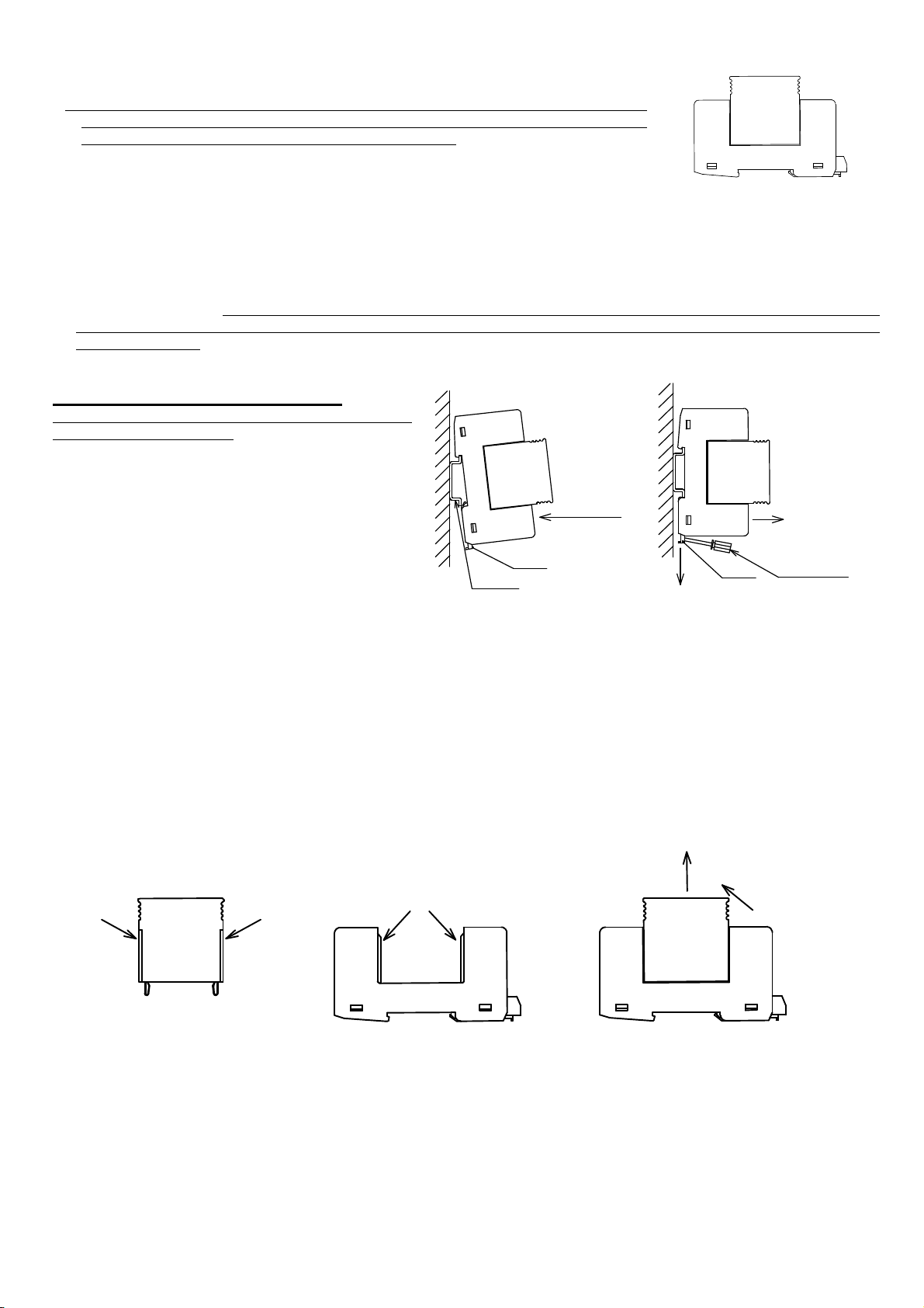
3) Installation and removing method of the SPD main unit (Ref : Fig.4, 5, 6, 7 )
a) When installing the SPD main unit, the concave of the SPD main unit (①part) should be fitted in the convex of
the fixing base(②part). Push the SPD main unit down to the fixing base securely until the end. If the SPD main
unit is not put in the fixing base until the end, the SPD may be no functioned normally.
b) When removing the SPD main unit from the fixing base, pull out with vertical direction (④part) while tilting
the SPD main unit towards to the direction of arrow head ③, holding the both grab side of the SPD main unit.
Fig.
3
Removing from DIN rail
Fig.
2
Installation
on DIN rail
F
ig.4
SPD
main unit
Fig.
5
Fixing base
Fig.
6
Removing method of SPD main unit
Fig.
1
SPD main unit
and fixing base
Main unit
Fixing base
DIN rail
Slider
①Position the
fixing base on
DIN rail
②Push the
fixing base
into DIN rail
①Pull the slider
Slider Screw driver
②Pull off
①① ②
③
④

3/4
3. Replace of the SPD main unit
The SPD main unit can be replaced when the SPD unlikely deteriorates.
(The status indicator on the SPD turns red and so on.)
When replacing the SPD main unit, please order the SPD main unit referred in Table 2.
If the right side of the SPD main unit is replaced, the type of it should be LSK-2520G. (Ref : Fig.8)
For the method of removing and installing the SPD main unit, refer to “Installation method of the SPD”
described in the item 2 of this manual.
Table 2 Type of SPD main unit (1 pcs)
4. Remote signaling contact
The SPD has a remote signaling contact as the changeover contact.
1) The specification of switching capacity is shown in Table 3.
Table 3 Specifications of switching capacity
2) The connection of signal wires is shown in Fig.9.
Fig.9 Connection of signal wires
Switching capacity [250VAC / 0.5A] [250VDC / 0.1A] [125VDC / 0.2A] [75VDC / 0.5A]
Applied electric wire 1.5mm2solid / flexible (Max.)
Pus
h the SPD main unit
down
until the end
not
to
space
Fig.7 Note of inserting condition of SPD main unit
Type of product Type of SPD main unit (1 pcs)
LSK-T2720S LSK-2720M
LSK-T3220S LSK-3220M
LSK-T3820S LSK-3820M
Normally open signal contact
Normally close signal contact
×
〇
SPD main unit SPD main unit
Ref : Table2 Type : LSK-2520G
SPD
SPD
Monitoring
Device
Monitoring
Device
Fig.8 SPD main unit

4/4
3) When the monitoring device is far from SPDs, please install the SPD for protecting the monitoring device from
induced lightning on the signal wires.
4) When connecting the signal wires to the signaling contact terminal, core wire of signal wire should not be out
from the terminal.
5. Regular maintenance
・During the lightning season, and after lightning strikes, maintain the SPD as follows.
・When the maintenance, the SPD must be isolated from the circuit by switching off the isolating switch on the
electric input side of the SPD, or removing the Backup Fuse shown in Table1, to prevent an electric shock.
1) If it is noted that the plastic housing has changed color or shape, replace the SPD.
2) If the status indicator on the SPD operates (Status indicator turns red), replace the SPD main unit.
6. Company
OTOWA ELECTRIC CO.,Ltd. (e-mail : overseas@otowadenki.co.jp)
Sales head office : 5-6-20, Shioe, Amagasaki-city, Hyogo Pref. 〒661-0976, JAPAN
Table of contents