OTS ET1100C Series User manual
ET1100C Series Installation & Operation Manual
www.ot-systems.com 1
Installation and Operation Manual
ET1100C Series
Ethernet Extender Series
Microtype10/100BASE-TX Ethernet Extender over Coaxial Cable
OT Systems Ltd., 2014
Rev 1.1

ET1100C Series Installation & Operation Manual
www.ot-systems.com 2
Models covered in this manual
Transmitter
ET1100C-T-MT
Receiver
ET1100C-R-MT

ET1100C Series Installation & Operation Manual
www.ot-systems.com 3
Table of Contents
TABLE OF CONTENTS............................................................................................................................................... 3
(1) SAFETY INSTRUCTIONS .................................................................................................................................. 4
(2) PRODUCT OVERVIEW .................................................................................................................................... 4
2.1 INTRODUCTION .....................................................................................................................................................4
2.2 PRODUCTS HIGHLIGHTS ..........................................................................................................................................4
(3) INSTALLATION................................................................................................................................................ 5
3.1 GENERAL ............................................................................................................................................................. 5
3.2 PACKAGE CONTENTS ..............................................................................................................................................5
3.3 SELECTING A SITE FOR THE ETHERNET EXTENDER .........................................................................................................6
3.4 INSTALLATION .......................................................................................................................................................6
(4) CABLE CONNECTIONS & SETUP PROCEDURES................................................................................................ 7
4.1 SYSTEM CABLE CONNECTIONS .................................................................................................................................. 7
4.2 CONNECTING TO YOUR NETWORK ............................................................................................................................ 8
4.2.1 The 10/100Base-TX Connector......................................................................................................... 8
4.2.2 The BNC connector and Coaxial Cable............................................................................................ 8
4.3 Cabling .................................................................................................................................................. 8
(5) OPERATIONAL GUIDES................................................................................................................................... 9
5.1 LEDS STATUS........................................................................................................................................................9
(6) SPECIFICATIONS............................................................................................................................................. 9
(7) DRAWINGS .................................................................................................................................................. 10
(8) WARRANTY INFORMATION ......................................................................................................................... 11
(9) CONTACT INFORMATION ............................................................................................................................. 11
APPENDIX A............................................................................................................................................................ A
1. CONNECTOR PINOUTS ................................................................................................................................... A

ET1100C Series Installation & Operation Manual
www.ot-systems.com 4
(1) Safety Instructions
Please be familiar with all information in this manual prior to installation and
operation.
Note 1: This assembly contains parts sensitive to damage by electrostatic discharge (ESD). ESD
precautionary procedures should be applied in the course of touching, removing or inserting parts
or assemblies.
(2) Product Overview
2.1 Introduction
OT Systems offers the perfect point-to-point solution to connect Ethernet technology to existing
coaxial installations. Designed to work in pairs, the ET1100C series offers upstream (receiver to
transmitter) connectivity for 300 meters up to 3 Mbps; downstream (transmitter to receiver)
connectivity for 300 meters up to 20 Mbps using single coaxial cables. This simple, plug-and-play
system and offers the OT Systems' design reliability. The ET1100C series is a perfect solution for
corporate campuses, industrial settings or any application where aging infrastructure must be
integrated with newer facilities and upgraded systems.
2.2 Products Highlights
Basic Features
One Ethernet port (RJ-45 connector): 10/100Mbps-Full/Half-duplex, Auto-MDI/MDIX,
Auto-negotiation.
One Ethernet Extender port (BNC connector): communications link over existing
coaxial cable.
Complies with IEEE802.3 10Base-T and IEEE802.3u 100Base-TX standards.
Provides F-Type BNC connector.
Operates transparent to higher layer protocols.
External DC power adapter.
Operating voltage and Max. Current consumption: 0.2A @ 12VDC.
Power consumption: 2.4W Max.
-10°C to 60°C (14°F to 140°F) operating temperature range.
Microtype design - fits within most camera housings
Plug-and-Play
Aluminum case.
Supports Wall-Mounting installation; Optional DIN-Rail mounting kit.

ET1100C Series Installation & Operation Manual
www.ot-systems.com 5
(3) Installation
3.1 General
All OT Systems products are thoroughly inspected, tested and securely packaged before
delivery to ensure a stable, intact and trouble-free service. Please check the equipment upon
receipt for any visible damage which may have been caused during shipping.
3.2 Package Contents
When you unpack the product package, you shall find the items listed below. Please inspect
the contents, and report any apparent damage or missing items immediately to your authorized
reseller.
Ethernet Extender
Quick Installation Guide
Wall-mounting kit or DIN-rail mounting
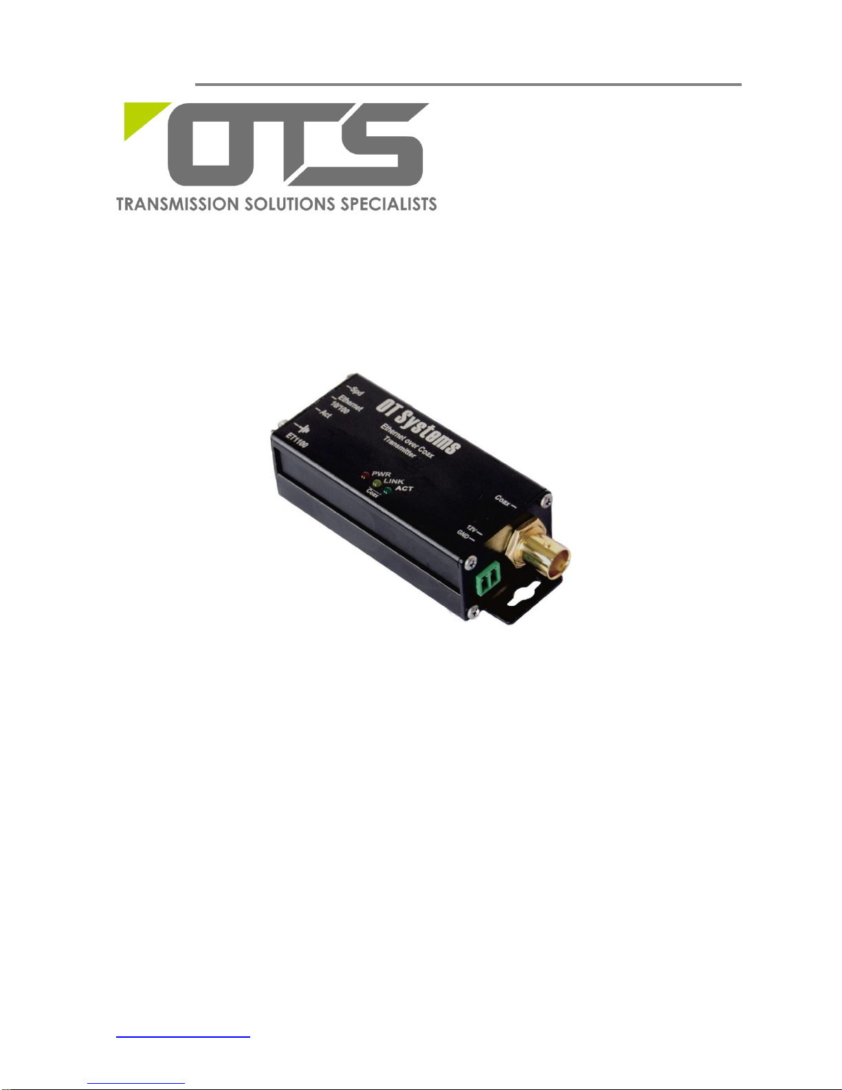
The ET1100C Series (Fig. 3.1) can be either horizontally or vertically wall-mounted, or
mounted on any fixture, etc. It works with an external 12VDC power supply which can be
purchased separately.
Fig. 3.1 ET1100C
ET1100C Series Installation & Operation Manual
www.ot-systems.com 6
3.3 Selecting a site for the Ethernet Extender
As with any electric device, you should place the equipment where it will not be
subjected to extreme temperatures, humidity, or electromagnetic interference.
Specifically, the site you select should meet the following requirements:
- The ambient temperature should be between -10 to 60 degrees Celsius.
- The relative humidity should be less than 95 percent, non-condensing.
- Surrounding electrical devices should not exceed the electromagnetic field (RFC)
standards.
- Make sure that the equipment receives adequate ventilation. Do not block the
ventilation holes on each side of the equipment.
- The power outlet should be within 1.8 meters of the product.
3.4 Installation
This chapter gives step-by-step instructions about how to install the Ethernet Extender:
The Microtype works with the provided external power supply (12VDC) powered by local 110/220V
power.
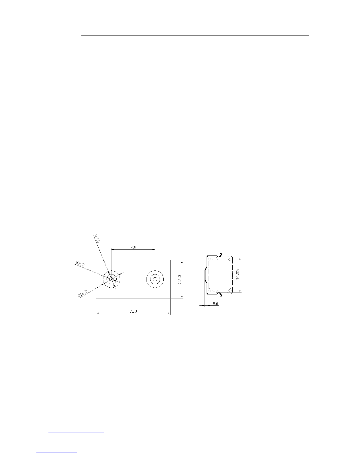
a) Mount the clip (Fig. 3.2) onto a fixture, e.g. a plank, (either on the wall or on a flat surface)
with two screws through the holes on the mounting frame to secure it in position.
(a) Front view (b) Side view
Fig. 3.2 Micro unit’s clip
b) The provided power supply should also be mounted on the same fixture or in the proximity
for connection of the supply cables to the unit, provided that an AC power supply socket is nearby
for powering the adaptor.
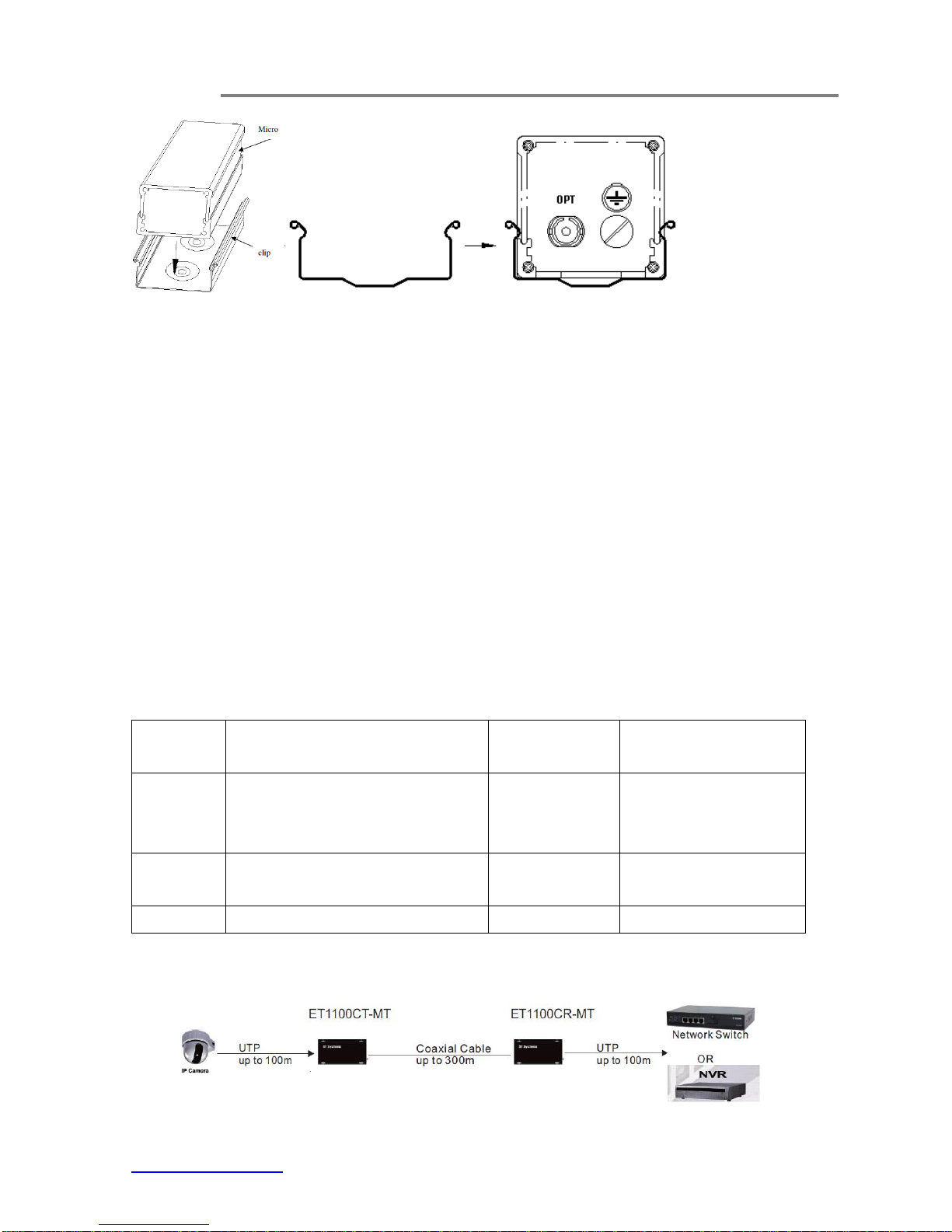
c) Push the Micro unit into the clip to secure it in position. For details, please follow Fig. 3.3.
ET1100C Series Installation & Operation Manual
www.ot-systems.com 7
(a) Installation (b) Side view of the clip (c) Side view of the Micro unit pushed into the clip
Fig. 3.3 Micro unit installation on the clip
d) Connect all the signal inputs and outputs at the back of the unit with appropriate cables:
i) Coaxial Cable
ii) UTP cable with RJ45
e) Once the unit is powered up, check that the red POWER LED on the unit is lit. If not, check
the power supply cable connections between the unit and the power supply socket.
f) With all the signals available at the input and output ports, check the status of LEDs located
on the unit. With correct status of each LED, installation is now completed [for LEDs status, see
Operational Guides on this manual’s section (5)].
(4) Cable Connections & Setup Procedures
4.1 System cable connections
Signal
Type
Cable Type
Connector
For details, please
refer to
Ethernet
Twisted-pair Cable
10BASE-T: 4-pair UTP/STP Cat3, 4, 5
100BASE-TX: 4-pair UTP/STP Cat 5
RJ45 Connector
Section 4.2.1
Line
Coaxial cable (RG6, RG58 or RG59)
BNC (Female)
75 Ohm
Section 4.2.2
12VDC
Power cord
DC Jack
Section 5
Wiring Diagram
Fig 4.1 Ethernet Extender connection diagram

ET1100C Series Installation & Operation Manual
www.ot-systems.com 8
4.2 Connecting to Your Network
Cable Type & Length
It is necessary to follow the cable specifications below when connecting the Ethernet
Extender to your network. Use appropriate cables that meet your speed and cabling
requirements.
Cable Specifications
4.2.1 The 10/100Base-TX Connector
A standard straight through cable is used for the connection between the Ethernet switch and
device. For the details, Please see Appendix A for your reference.
4.2.2 The BNC connector and Coaxial Cable
For the Ethernet Extender port
4.3 Cabling
Step 1: First, ensure the power of the Ethernet Extender and end devices are turned off.
<Note> Always ensure that the power is off before any installation.
Step 2: Prepare cable with corresponding connectors for each type of port in use.
Step 3: Consult the previous section for cabling requirements based on connectors and speed.
Step 4: Connect one end of the cable to the Ethernet Extender and the other end to a desired device.
Step 5: Once the connections between two end devices are made successfully, turn on the power and the
Ethernet Extender is operational.
Speed
Connector
Cable
Max.
Distance
10Base-T
RJ-45
2-pair UTP/STP Cat. 3, 4, 5
100 m
100Base-TX
RJ-45
2-pair UTP/STP Cat. 5
100 m
Connector
Cable
Max.
Distance
BNC (75Ω)
Coaxial Cable (RG6, RG58 or RG59)
300m

ET1100C Series Installation & Operation Manual
www.ot-systems.com 9
(5) Operational Guides
5.1 LEDs Status
LEDs
State
Indication
PWR
Green
Power on.
Off
Power off.
Link
Amber
Data is avaible at coxical cable
ACT
Flashing
Transmitting or receiving Ethernet data, Act stands for ACTIVITY
Off
Neither valid Ethernet connection established nor transmitting/receiving Ethernet data
Ethernet
Lnk/Act
Steady
A valid Ethernet connection established, Lnk stands for LINK
Flashing
Transmitting or receiving Ethernet data, Act stands for ACTIVITY
Off
Neither valid Ethernet connection established nor transmitting/receiving Ethernet data
Spd
Steady
Ethernet Connection transferring at 100Mbps
Off
Ethernet Connection transferring at 10Mbps
Signal and Power Ports
10/100 Ethernet-
RJ45 with Cat. 5 for Ethernet connection.
COAX -
BNC connecter with Coaxial cable connection
DC12V-
2-pin screw terminal for 12VDC power connection.
(6) Specifications
Ethernet
Standards
IEEE 802.3 10BASE-T
IEEE 802.3u 100BASE-TX
IEEE 802.3x
Processing Type
IEEE 802.3x Full-duplex flow control
Cabling
10BASE-T
100BASE-TX
4-pair UTP/STP Cat. 3, 4, 5
4-pair UTP/STP Cat. 5
Maximum Distance
Cat5 UTP
Up to 100m
Connector
10/100BASE-TX
1X RJ45
Coaxial
ET1100C Series Installation & Operation Manual
www.ot-systems.com 10
Cabling
Coaxial Cable (RG6, RG58 or RG59)
Maximum Distance
300m
Connector
BNC (75 ohm)
Electrical and Mechanical
Input Power
12VDC
Power Consumption
2.4W Max.
Max. Current Consumption
& Operating Voltage
0.2A @ 12VDC
LED Indicators
PWR
Power Status
10/100 TX
Link/Activity, Speed
Dimensions
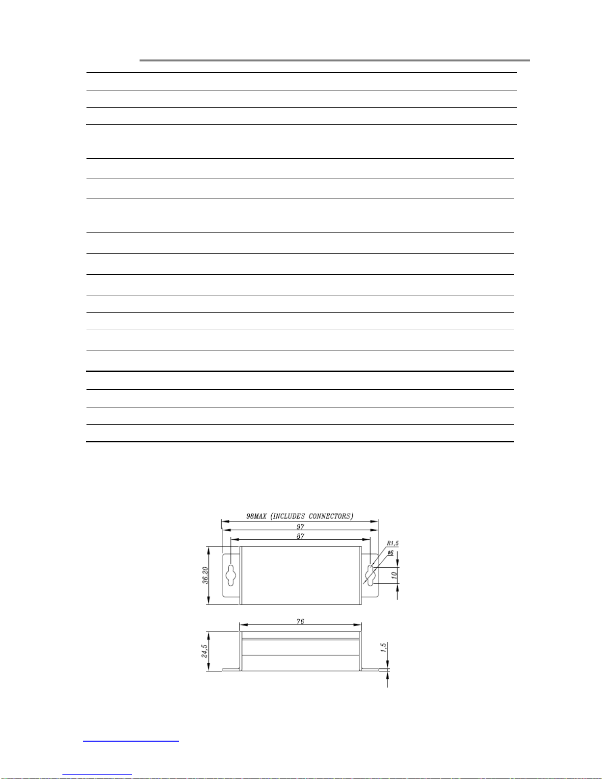
36.2mm (W) × 24.5 mm (D) × 98mm (H)
Net Weight
0.1Kg (0.25Kg including PA)
Casing
Aluminum case
Mounting Options
Wall-Mount
Environmental
Operating Temperature
-10°C to 60°C (14°F to 140°F)
Storage Temperature
-40°C to 85°C (-40°F to 185°F)
Humidity
5% - 95% non-condensing
(7) Drawings
Fig. 7.1 Dimensional drawings of ET1100C (mm)

ET1100C Series Installation & Operation Manual
www.ot-systems.com 11
(8) Warranty Information
All OT Systems ET Series products are subject to a three-year limited warranty offered by
the company in normal circumstances. Please refer to the OT Systems Products Warranty
Statement for details. Access to the statement is available in our company website at
www.ot-systems.com.
(9) Contact Information
APAC Operation
Address:
Unit 1023, 10/F, Landmark North,
39 Lung SumAvenue, Sheung
Shui, N.T., Hong Kong
Tel: (852) 2672 5153
Fax: (852) 2679 0756
Sales Inquiries
sales@ot-systems.com
Technical Support
techsupport@ot-systems.com
EMEAOperation
Address:
J. Slovackio str. 4, LT-11107,
Vilnius, Lithuania
Tel: (370) 60730087
Fax: (370) 52051855
Sales Inquiries
sales@ot-systems.com
Technical Support
techsupport@ot-systems.com
AMERICAS Operation
Address:
18 West Main Street, Plano,
IL 60545, U.S.A.
Tel: (1) 630 554 9178
Fax: (1) 630 554 9179
Sales Inquiries
sales.usa@ot-systems.com
Technical Support
techsupport.usa@ot-systems.com

Appendix A
www.ot-systems.com A
Appendix A
1. Connector Pinouts
RJ45 Connector (Male)
RJ45 Connector (Female)
2. TIA/EIA-568 Cabling
RJ45
Pin #
T568A
T568B
Wire Diagram
Wire Color
10Base-T Signal
100Base-TX Signal
Wire Diagram
Wire Color
10Base-T Signal
100Base-TX Signal
1
White/Green
Transmit+
White/Orange
Transmit+
2
Green
Transmit-
Orange
Transmit-
3
White/Orange
Receive+
White/Green
Receive+
4
Blue
Unused
Blue
Unused
5
White/Blue
Unused
White/Blue
Unused
6
Orange
Receive-
Green
Receive-
7
White/Brown
Unused
White/Brown
Unused
8
Brown
Unused
Brown
Unused
3. Standard, Straight-Through Wiring Diagram(both ends are the same):
The Straight-Through wiring (or called “regular” Ethernet cable), both ends should be use the
same pin out on of RJ45 port.
Table of contents
Popular Extender manuals by other brands

Scion-Tech
Scion-Tech SC01.7060 user manual

Niles
Niles MF2VF Specification sheet

Enable-IT
Enable-IT 860 XS PRO quick start guide

DH Instruments
DH Instruments GB-152 Operation and maintenance manual

Hall Research Technologies
Hall Research Technologies EX-HDMI-2A user manual

Digiality
Digiality REMOTE CONTROL owner's manual

Thender
Thender CH1109TXC Operation manual

Cypress
Cypress Suprex SPX-7200 Operation manual

Elisra
Elisra MW-IBDB-10W40-PS9 Installation and operating instructions

Rose electronics
Rose electronics CrystalLink CAT5 Serial quick start guide

StarTech.com
StarTech.com IREXT instruction manual

Rose electronics
Rose electronics CrystalView Plus quick start guide


