Otto Bock Harmony P3 4R147 User manual

HarmonyP3 4R147
Gebrauchsanweisung ........................................................................................................... 5
Instructions for use ..............................................................................................................13
Instructions d‘utilisation .......................................................................................................21
Istruzioni per l’uso ...............................................................................................................29
Instrucciones de uso ...........................................................................................................37
Manual de utilização ............................................................................................................45
Gebruiksaanwijzing .............................................................................................................53
Bruksanvisning ...................................................................................................................61
Brugsanvisning ...................................................................................................................69
Bruksanvisning ...................................................................................................................77
Instrukcja użytkowania .........................................................................................................85
Návod k použití ...................................................................................................................93
Kullanma talimatı ............................................................................................................... 101
Οδηγίες χρήσης ................................................................................................................109
Руководство по применению .............................................................................................118
取扱説明書 (義肢装具士用) .................................................................................................127

2 | Ottobock HarmonyP3 4R147
1
1
4
2
3
6
5
2
7
8
9
5
10
6
11
>=
63,5 mm
(2½ in)
3 4

Ottobock | 3HarmonyP3 4R147
8
7
2
1
34
5
6

4 | Ottobock HarmonyP3 4R147
10
9
11
1
2
3
12
1
2
3

Ottobock | 5HarmonyP3 4R147
Deutsch
INFORMATION
Datum der letzten Aktualisierung: 2015-07-01
• Lesen Sie dieses Dokument vor Gebrauch des Produkts aufmerksam durch.
• Beachten Sie die Sicherheitshinweise, um Verletzungen und Produktschäden zu vermeiden.
•
Weisen Sie den Benutzer in den sachgemäßen und gefahrlosen Gebrauch des Produkts ein.
• Bewahren Sie dieses Dokument auf.
Bedeutung der Symbolik
VORSICHT Warnungen vor möglichen Unfall- und Verletzungsgefahren.
HINWEIS Warnungen vor möglichen technischen Schäden.
INFORMATION Weitere Informationen zur Versorgung/Anwendung.
INFORMATION
Bitte lesen Sie diese Bedienungsanleitung aufmerksam durch. Beachten Sie besonders
die angeführten Sicherheitshinweise!
1 Lieferumfang
Zum Lieferumfang der Harmony P3-Pumpe gehört:
1. 4R147 Harmony P3-Pumpe (inkl. Funktionsring 4X147*)
2. 2R117 Schaftanschluss (2x)
3. 4Y360 Schalldämpfer
4. 4Y383 Flansch Kit
5. 647H14 Bedienungsanleitung
* Weitere Versionen des 4X147 Funktionsringes können getrennt bestellt werden (Auswahlmög-
lichkeiten siehe Kapitel 4.5.1).
2 Gerätebeschreibung
2.1 Verwendungszweck
Die Harmony P3-Pumpe ist Bestandteil des Harmony-Schaftsystems für erhöhten Unterdruck. Zu
diesem System gehören außerdem ein Vollkontaktschaft, ein Polyurethan-Liner, ein Stumpfstrumpf
und eine Kniekappe. Das Harmony-System ist ausschließlich für die prothetische Versorgung der
unteren Extremität einzusetzen.

6 | Ottobock HarmonyP3 4R147
2.2 Einsatzgebiet
1
2
3
4
<
7
5
<
1
0
0
<
1
2
5
<
1
5
0
Einsatzgebiet nach dem Ottobock Mobilitätssystem MOBIS:
Empfehlung für Amputierte der Mobilitätsgrade 2 bis 4 (eingeschränkter Au-
ßenbereichsgeher, uneingeschränkter Außenbereichsgeher, uneingeschränkter
Außenbereichsgeher mit besonders hohen Ansprüchen).
Zugelassen bis 125 kg Patientengewicht. Zum Aktivieren der Pumpe ist ein Min-
destgewicht von 40 kg erforderlich.
2.3 Sicherheitshinweise
2.3.1 Allgemeine Sicherheitshinweise
VORSICHT
Gesundheitsgefährdung bei Verwendung eines falschen Prothesenschaftes. Die Anwendung
falscher Schaft-Techniken kann zu einer Gesundheitsgefährdung des Patienten führen (vermehrte
Flüssigkeitsansammlung im Stumpf, z.B. Ödeme). Der Prothesenschaft ist ausschließlich in
Harmony-Technik zu erstellen.
HINWEIS
Funktionsverlust durch mechanische Beschädigungen. Bei erkennbarer Beschädigung des
Funktionsringes ist ein ordnungsgemäßer Betrieb des Gerätes nicht gewährleistet (erhöhter
Unterdruck kann nicht aufgebaut werden).
Der Funktionsring ist vor mechanischen Beschädigungen zu schützen. Bei erkennbarer Beschädi-
gung muss der Funktionsring durch Fachpersonal ausgetauscht werden (siehe Kapitel 4.5 und 5).
HINWEIS
Funktionsverlust bei nicht ordnungsgemäßer Anwendung. Der Patient ist in den ordnungsgemäßen
Gebrauch der Harmony-Pumpe und des Harmony-Systems zu unterweisen (siehe Kapitel 2.3.2).
2.3.2 Patientenhinweise
Bitte geben Sie diese Informationen an Ihre Patienten weiter:
HINWEIS
Funktionsverlust durch verschmutzte Ventile. Die richtige Wartung und Pege erfordert, dass
das Harmony-System regelmäßig mit 30–60 ml destilliertem Wasser mit ca. 5 bis 10 Pumpzyklen
durchgespült wird, um die Ventile zu reinigen. Wird das Problem durch Spülen nicht behoben,
können die Kunststoffventile (4Z106 gerade und 4Z108 Ellenbogen) leicht ausgetauscht wer-
den (siehe Abbildung 8).
INFORMATION
•
Seien Sie vorsichtig im Umgang mit der Harmony-Pumpe und untersuchen Sie die Pumpe
regelmäßig auf sichtbare Beschädigungen und Verschleiß.
•
Arbeiten Sie mit Ihrem Orthopädie-Techniker zusammen, um nachzuvollziehen, wie es sich
anfühlt, wenn das Harmony-System richtig funktioniert oder der Unterdruck nachlässt und
wie sich ein erhöhter Unterdruck insgesamt auf den Stumpf auswirkt.

Ottobock | 7HarmonyP3 4R147
2.4 Qualikation des Orthopädie-Technikers
Die Versorgung eines Patienten mit einem Harmony-System darf nur von Orthopädie-Technikern
vorgenommen werden, die von Ottobock durch eine entsprechende Schulung autorisiert wurden.
2.5 Funktion
2.5.1 Bezeichnung der Bauteile (Abb. 1)
(1) Schaft
(2) Basiskörper
(3) Klemmring
(4) Funktionsring
(5) Einlassventil
(6) Auslassventil
2.5.2 Vakuumpumpe
Die Harmony P3-Pumpe ist eine mechanische Pumpe, die in einem Prothesenschaft einen erhöhten
Unterdruck erzeugen kann und dadurch die Verbindung zwischen Patient und Prothese verbessert.
Das System besteht aus einem Polyurethan-Liner, einem Stumpfstrumpf, einem festen Schaft (der
mit der Pumpe verbunden ist), einer Kniekappe und der Harmony P3-Pumpe.
Sobald das System abgedichtet ist, entzieht der Funktionsring – der beim normalen Gehen kom-
primiert und wieder entspannt wird – durch Einweg-Ventile Luft aus dem Schaftinneren und saugt
sie durch die Pumpe ab. Nach mehreren Kompressionszyklen wird ein erhöhter Unterdruck von
508–847mbar (15 –25 in Hg) im abgedichteten Schaftbereich erreicht.
2.5.3 Stoßdämpfer und Rotationsfunktion
Der Funktionsring in der Harmony P3-Pumpe hat eine Stoßdämpfungs- und Rotationsfunktion.
Diese tragen dazu bei, vertikale Kräfte und Drehmomente in den Extremitäten beim Gehen abzu-
schwächen. Das Ergebnis ist eine Verbesserung sowohl der Funktion als auch der Belastungs-
situation des Prothesenträgers.
3 Technische Daten
Harmony P3-Pumpe 4R147
Gewicht der Pumpe 400 Gramm
Höhe der Pumpe 117 mm (4.6 in)
Systemhöhe der Pumpe 175 mm (6.9 in)
Gewichtsbereich 40–125 kg (88 –276 lbs)
Anzugsmomente Gewindestifte der Aufnahme (Abb. 2, Pos. 7 und 8): 15 Nm (133 in-lbs)
Klemmringschraube (Abb. 2, Pos. 9): 10 Nm (88 in-lbs)
Halteschraube (Abb. 5, Pos. 10): 7 Nm (60 in-lbs)
Material Aluminium/Titan/Nylon

8 | Ottobock HarmonyP3 4R147
4 Handhabung
VORSICHT
Gesundheitsgefährdung bei Verwendung eines falschen Prothesenschaftes. Die Anwendung
falscher Schaft-Techniken kann zu einer Gesundheitsgefährdung des Patienten führen (vermehrte
Flüssigkeitsansammlung im Stumpf, z.B. Ödeme). Der Prothesenschaft ist ausschließlich in
Harmony-Technik zu erstellen.
4.1 Schaftanschluss anbringen
Bei einem neuen Schaft, ein 6 mm Loch in den Schaft in einer distalen, hinteren Position bohren.
Bei Schäften mit einem 4R136 oder 4R138=5 Ottobock Einweg-Ventil, das Ventil aus dem Schaft
nehmen und in das vorhandene Loch bohren. Schaftinnenseite entgraten. Mit mittelkörnigem
Sandpapier den Außenbereich des Schaftes leicht schleifen um die Klebeäche aufzurauhen.
Zur Reinigung, die Klebeäche mit Isopropyl-Alkohol abwischen. Den Schaftanschluss 2R117
ebenfalls mit Isopropyl-Alkohol reinigen.
Als nächstes, eine dünne Schicht Klebstoff (Ottobock empehlt den Zweikomponenten Urethan
Kleber SL=P091) auf die ebene Fläche des Flansches sowie auf den Bund auftragen. Darauf
achten, dass kein Kleber auf das spitz zulaufende Ende gelangt.
Das spitz zulaufende Ende des Flansches in die 6 mm Bohrung einführen, wobei der Schlauch
zur Harmony-Pumpe weist. Mit einer Spitzzange das spitz zulaufende Ende des Flansches in den
Schaft hineinziehen, bis die ebene Fläche des Flansches fest an der Außenäche des Schaftes
anliegt. Den Flansch mit Vinyl-Band befestigen. Mindestens 45 Minuten aushärten lassen.
Anmerkung: Bei besonders tiefen oder schmalen Schäften kann der spitz zulaufende Flansch zu-
erst mit einem Stift markiert und dann herausgenommen und geschnitten werden. Es könnte dabei
ein etwas größeres Loch (6,5 mm) erforderlich sein. Dann wie bei einem normalen Schaft kleben.
Mit einem abgerundeten Messer das spitz zulaufende Ende des Flansches im Schaft kürzen. Es
sollte bündig mit der Innenäche des Schaftes abschließen.
4.2 Befestigung von Schaft und Adapter an der Harmony P3-Pumpe
Gewindestifte an der proximalen Aufnahme des Schaftes (Abb. 2, Pos. 7) am Justierkern mit ei-
nem Anzugsmoment von 15 Nm (133 in-lbs) anziehen. Für die Endeinstellung mit 636K13 Loctite®
241 sichern.
4.3 Befestigung des Rohradapters an der Harmony P3-Pumpe
INFORMATION
• Die Pumpe 4R147 ist mit einem 34 mm Rohradapter zu verwenden.
•
Der Rohradapter darf höchstens auf eine Länge von 63,5 mm (2 ½ in) gekürzt werden (Abb. 3).
• Das Rohr reicht 42 mm (1.65 in) in die Pumpe hinein.
•
Wird der Rohradapter kürzer als 100 mm (4 in) geschnitten, ist sicherzustellen, dass der Kleber
am inneren Durchmesser des Rohradapters (Abb. 4) die blaue Schraube und Unterlegscheibe
am distalen Ende der Pumpe nicht stört. Mit einem Messer überschüssigen Kleber abkratzen.
Den Rohradapter auf die erforderliche Länge schneiden; den Rohradapter vollständig in das
distale Ende der Pumpe einführen. Die Klemmringschraube (Abb. 2, Pos. 9) mit einem Anzugs-
moment von 10 Nm (88 in-lbs) anziehen. Für die Endeinstellung mit 636K13 Loctite® 241 sichern.

Ottobock | 9HarmonyP3 4R147
4.4 Schaftanschluss anschließen
Den Schaftanschlussschlauch auf die richtige Länge schneiden, die schwarze Schlauchschutz-
hülle 4Y310 auf den Schaftanschluss aufziehen. Das proximale Einlassventil (Abb. 1, Pos. 5)
an der Harmony P3-Pumpe montieren und die Schlauchschutzhülle herunter drücken um den
Schaftanschluss zu sichern.
4.5 Auswahl und Einstellung des Funktionsringes
HINWEIS
Funktionsverlust bei nicht ordnungsgemäßer Anwendung. Die Auswahl/Einstellung des Funkti-
onsringes darf nur durch von Ottobock autorisierte Orthopädie-Techniker vorgenommen werden.
4.5.1 Auswahl des geeigneten Funktionsringes
Die Auswahl eines geeigneten Funktionsringes erfolgt anhand der nachfolgenden Auswahl-Tabelle.
Die Ausführung des Funktionsringes kann der Markierung an der Aufnahme des Einlassventils
entnommen werden (Abb. 8).
Körpergewicht Empfohlener Funktionsring
kg lbs
40–47 88 –103 0
48–55 104 –121 1
56–65 122 –143 2
66–75 144 –165 3
76–87 166 –192 4
88–100 193 –220 5
101–112 221 –247 6
113–125 248 –276 7
Es ist zu beachten, dass die Empfehlungen nicht zwangsläug die optimale Auswahl für den Pa-
tienten darstellen. Bei Abweichung von den Auswahldaten sollte der Funktionsring mit der höchst-
möglichen Steigkeit ausgewählt werden, der aber noch ausreichend Vakuum erzielt. Ottobock
empehlt, dass ca. 500 mbar (15 in Hg) oder mehr innerhalb von 50 Schritten mit der Prothese
erreicht werden sollten.
Signalisiert der Patient ein zu starkes Einsinken, sollte ein steiferer Funktionsring verwendet wer-
den. Generiert die Pumpe keinen ausreichenden Unterdruck, sollte ein weicherer Funktionsring
verwendet werden.
4.5.2 Wechseln des Funktionsringes
1.
Halteschraube am distalen Ende der Pumpe lösen (Abb. 5, Pos. 10) und entfernen (Abb. 7,
Schritt 1). Bei vollständig montierter Pumpe zunächst den Rohradapter mit Fuß entfernen.
2. Den Basiskörper vom Schaft abziehen (Abb. 7, Schritt 2).
3. Den montierten Funktionsring abziehen (Abb. 7, Schritt 3).
4. Den gewünschten Funktionsring wählen (Abschnitt 4.5.1).
5. Vorbereitung des Funktionsringes für die Erstverwendung
Vor dem ersten Einsatz, wird von Ottobock empfohlen, dass separat bestellte Funktionsringe mit
dem separat erhältlichen Vorkomprimiergerät 4X247 vorkomprimiert werden um eine einwand-

10 | Ottobock HarmonyP3 4R147
freie Funktion zu gewährleisten. Ohne Vorkomprimierung können neue Funktionsringe übermäßig
steif sein. Bei Verwendung eines vorinstallierten Funktionsringes oder einer vorkomprimierten
Einheit, bitte mit Schritt 6 fortfahren.
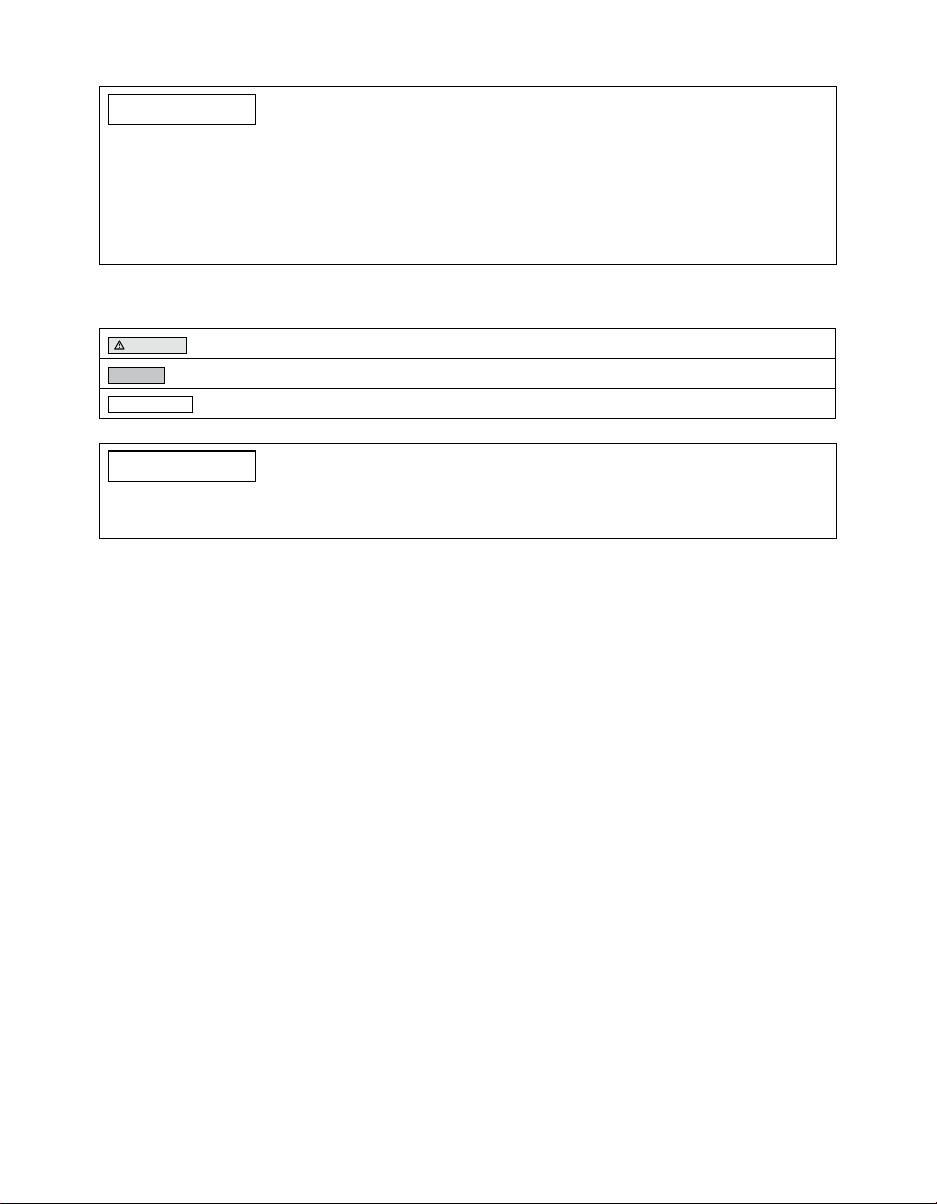
a. Das Vorkomprimiergerät öffnen
b. Den Funktionsring in das Vorkomprimiergerät einsetzen (Abb. 9)
c. Den Funktionsring durch vollständiges Festziehen der Schraube vollständig komprimieren
(Abb. 10)
d. Kompressionsdauer: Mindestens 3 Minuten bis maximal 15 Minuten
e. Das Vorkomprimierungsgerät öffnen, den Funktionsring herausnehmen und in die Pumpe
einsetzen
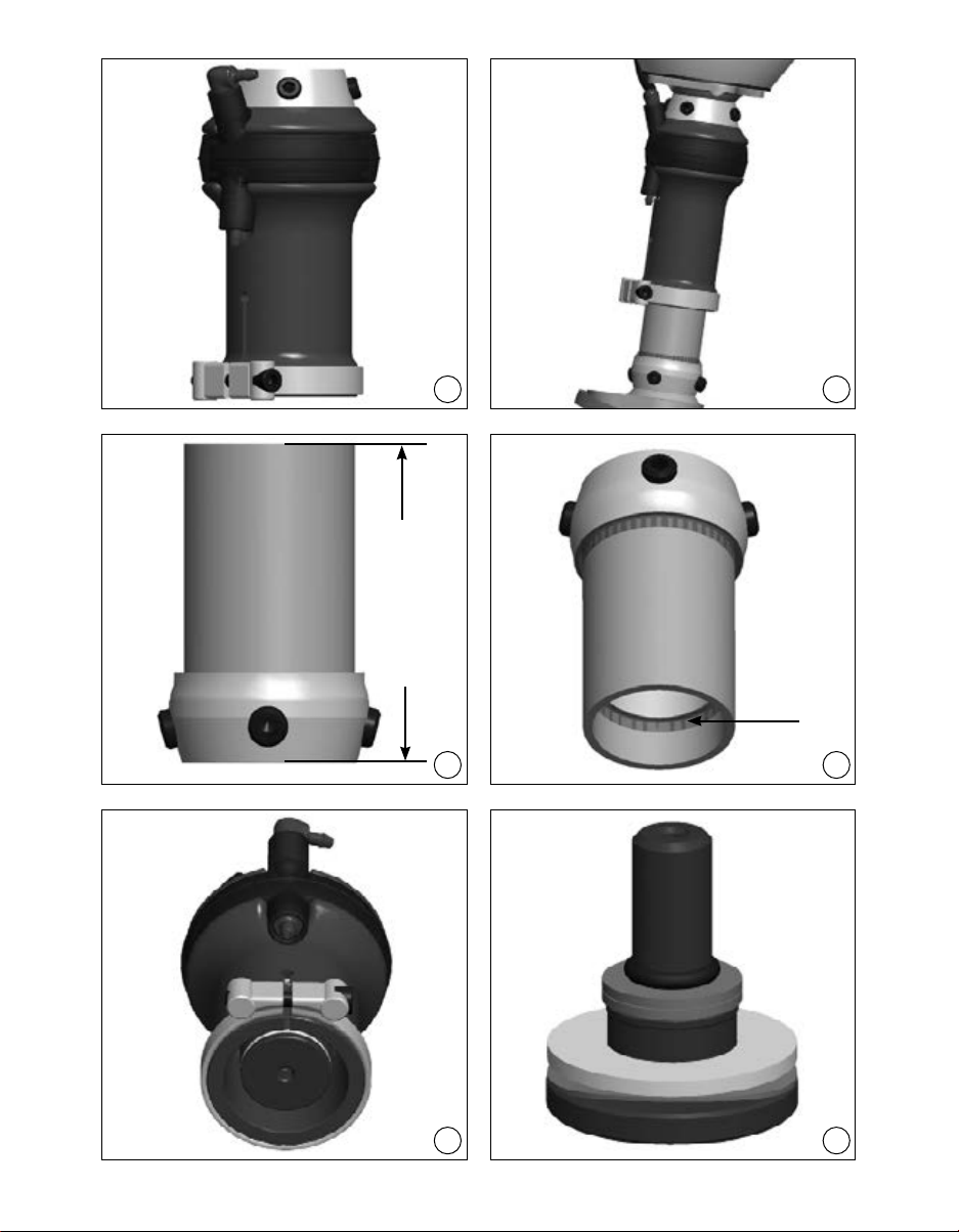
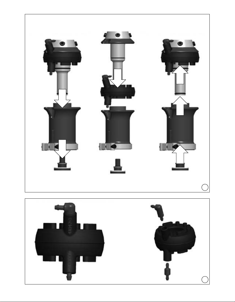
6. Den Funktionsring über den Schaft schieben (Abb. 7, Schritt 4).
7. Die Pumpe wieder zusammensetzen (Abb. 7, Schritte 5 und 6).
8. Die Halteschraube mit 636K13 Loctite® 241 sichern und im Uhrzeigersinn mit 7 Nm (60 in-lbs)
festziehen.
9. Rohradapter und Fuß wieder zusammenbauen.
4.5.4 Feinjustierung der Pumpensteigkeit
Die grobe Einstellung der Kompressionssteigkeit der Pumpe wird über die Funktionsring-Auswahl
festgelegt. Eine Feinjustierung der Kompressionssteigkeit kann durch Hinzufügen oder Entfernen
von Unterlegscheiben erzielt werden (Abb. 6, Pos. 11).
1. Halteschraube am distalen Ende der Pumpe lösen (Abb. 5, Pos. 10).
2.
Die Pumpe wird mit 2 Unterlegscheiben an der Halteschraube ausgeliefert. Es dürfen nicht
mehr als zwei Scheiben verwendet werden. Es können eine Scheibe oder auch beide Scheiben
entfernt werden. Die Scheiben werden mit einem kleinen O-Ring auf der Schraube gehalten.
Der O-Ring hat keine weitere Funktion.
a) Durch Entfernen einer Scheibe wird die Vorspannung des Funktionsringes erhöht, wodurch
sich die vertikale Verschiebung (und die Extension der Pumpe während der Schwungphase)
verringern. Zusätzlicher Effekt: leichte Abnahme des maximal erreichbaren Unterdrucks.
b) Durch Hinzufügen einer Scheibe wird die Vorspannung des Funktionsringes reduziert, wodurch
sich die vertikale Verschiebung (und die Extension der Pumpe während der Schwungphase)
erhöhen. Zusätzlicher Effekt: leichte Zunahme des maximal erreichbaren Unterdrucks.
3. Erreichten Unterdruck testen, sobald die gewünschte Stoßdämpfung erreicht ist.
4.6 Überwachung des erhöhten Unterdrucks
Um zu prüfen, ob das Harmony-System einen erhöhten Unterdruck aufrechterhält, muss vorüber-
gehend das mitgelieferte Manometer 755Z37 (separat über Ottobock erhältlich) angeschlossen
werden.
1. Dazu den Schaftanschluß vom Einlassventil der Harmony P3-Pumpe abnehmen.
2.
Nun den Schlauch des Manometers (kurze Seite) an das Einlassventil der Pumpe und den lose
hängenden Schaftanschluss an das offene Schlauchansatzstück am Manometer anschließen.
3.
Stehenden Patienten mit korrekt angelegtem Harmony-System die Harmony P3-Pumpe betätigen
lassen, um einen Unterdruck zwischen 508-847 mbar (15–25 in Hg) aufzubauen.
4.
Pumpe nicht mehr betätigen. Das System funktioniert richtig, wenn der Unterdruck bestehen
bleibt. Lässt der Unterdruck nach, muss das System überprüft werden (siehe Kapitel 4.6.1).

Ottobock | 11HarmonyP3 4R147
4.6.1 Störungssuche im System bei nachlassendem Unterdruck
Um festzustellen, ob der Verlust an Unterdruck in Bereich 1, 2 oder 3 auftritt (Abb. 11), ist das
Manometer – wie in Kapitel 4.6 beschrieben – anzuschließen. Anschließend folgende Schritte
durchführen:
Ablaufplan:
Loch auf der Schaftinnenseite mit einem kleinen Stück Papier und luftdichtem Klebeband (z.B.
PVC-Band) abdichten. Pumpe betätigen, bis ein Unterdruck von 508-847 mbar (15–25 in Hg)
erreicht ist. Pumpe nicht mehr betätigen und überprüfen, ob das Vakuum erhalten bleibt.
Vakuum bleibt erhalten:
Bereich 2 and 3 sind in Ordnung
Bereich 1 (Schaft und Kniekappe) auf durch-
lässige Stellen überprüfen
Vakuum bleibt nicht erhalten:
Das Problem bendet sich in Bereich 2 oder 3.
Mit abgenommenem T-Stück das Manometer direkt an das Einlassventil (Abb. 1, Pos. 5)
anschließen und die Pumpe betätigen bis ein Vakuum von 508-847 mbar (15–25 in Hg) erreicht
ist. Pumpe nicht mehr betätigen und überprüfen, ob das Vakuum erhalten bleibt.
Vakuum bleibt erhalten:
Bereich 3 ist in Ordnung
Das Problem bendet sich im Schaftan-
schluss bzw. dessen Verklebung mit
dem Schaft. Auf durchlässige Stellen oder
Beschädigungen untersuchen.
Vakuum bleibt nicht erhalten:
Es besteht ein Problem in den Ventilen oder
dem Funktionsring
Ventile ersetzen und nochmals prüfen
Vakuum bleibt erhalten:
Die Ventile auswechseln
Vakuum bleibt nicht erhalten:
Problem bendet sich im Funktionsring
Den Funktionsring ersetzen
4.7 Kosmetikabschluss der Prothese
Zum Lieferumfang der Harmony P3-Pumpe gehören zwei verschiedene Ausstoßventil-Anschlüsse:
•
ein kurzes Schlauchstück mit installiertem Dämpfer und einem Verbinder mit doppeltem Wider-
haken, vorinstalliert am Ausstoßventil;
• ein langes Schlauchstück mit einem Ausstoßansch
Wird ein kosmetischer Überzug auf der Prothese gewünscht, ist ein Überzug mit einem 34 mm
Zentralloch zu verwenden.

12 | Ottobock HarmonyP3 4R147
HINWEIS
Funktionsverlust bei nicht ordnungsgemäß montiertem kosmetischem Überzug. Bei Verwen-
dung eines 6R8 Schaumüberzugs ist es wichtig, dass der Überzug nicht entlang der Schaum-
stofänge komprimiert wird, da dies die Funktion der Harmonie Pumpe beeinträchtigen kann.
Nachdem der Schaumüberzug platziert worden ist, muss die Position des Ausstoßansches
bestimmt und ein 6 mm Loch gebohrt oder geschnitten werden. Ottobock empehlt, dass der
Absaugansch medial am Knöchel, etwas über dem Schuhoberteil des Patienten platziert wird.
Als nächstes werden Schlauch (Abb. 12, Pos. 2) und Flansch (Abb. 12, Pos. 3) in das Loch im
Kosmetiküberzug eingeführt und der Schlauch am Verbinder mit Doppelwiderhaken befestigt
(Abb. 12, Pos. 1). Es ist dabei sicherzustellen, dass der Schlauch in keiner Weise geknickt oder
zusammengedrückt wird. Der Flansch kann bei Bedarf in Position geklebt werden: Dazu wird eine
dünne Schicht des Klebstoffs auf die Flanschäche aufgetragen und der Flansch dann angepresst.
Wenn der Flansch fest sitzt, kann ein Stück überschüssiger Schlauch zurechtgeschnitten oder ein-
fach in die Kosmetik gedrückt werden, bis das Schlauchende bündig mit dem Flansch abschließt.
Anmerkung: Um die beste kosmetische Wirkung zu erzielen, empfehlen wir, dass der Schaum-
überzug mit einem Soft Touch Trikotschlauch überzogen wird.
Anmerkung: Salz auf der Außenseite des Trikotschlauches kann mit warmem Wasser wegge-
spült werden.
5 Wartung
Ottobock empehlt, dass der 4X147 Funktionsring etwa nach 1 Jahr Gebrauch ausgewechselt
wird, da seine Steigkeit und die Rückstellkraft im Laufe der Zeit abnehmen können. Es handelt
sich um ein Verschleißteil, bei dem sich dieser Zeitpunkt, in Abhängigkeit von Aktivität und Um-
weltbedingungen nach vorne oder nach hinten verschieben kann. Typische Indikatoren, die dem
Patienten auffallen können, sind reduzierte Stoßdämpfung und langsamerer Unterdruck-Aufbau.
Hinweis:Neue Funktionsringe können sich während der ersten Anwendungstage für den Pati-
enten steifer anfühlen.
Nimmt die Unterdruckleistung ab ohne dass dabei die Stoßdämpfungsleistung abnimmt, kann es
sein, dass eine oder beide Ventile mit Schmutz verstopft sind. Die beste Abhilfe ist ein Auswech-
seln der Ventile. Beim Herausnehmen der Ventile, eventuell angesammelten Schmutz mit Druckluft
aus dem Funktionsring herausblasen.
Beim Service-Intervallmäßigem Auswechseln des Funktionsringes alle alten Schmierfettreste vom
Schaft und den Lagern entfernen; danach neues Schmierfett auftragen und die beiden O-Ringe
am Schaft ersetzen. Diese O-Ringe haben keinen Einuss auf die Unterdruck-Leistung. Sie dienen
dazu, die unerwünschte aber notwendige Bewegung im Lagersystem zu dämpfen.
6 Rechtliche Hinweise
Alle rechtlichen Bedingungen unterliegen dem jeweiligen Landesrecht des Verwenderlandes und
können dementsprechend variieren.
6.1 Haftung
Der Hersteller haftet, wenn das Produkt gemäß den Beschreibungen und Anweisungen in diesem
Dokument verwendet wird. Für Schäden, die durch Nichtbeachtung dieses Dokuments, insbeson-
dere durch unsachgemäße Verwendung oder unerlaubte Veränderung des Produkts verursacht
werden, haftet der Hersteller nicht.

Ottobock | 13HarmonyP3 4R147
6.2 CE-Konformität
Das Produkt erfüllt die Anforderungen der europäischen Richtlinie 93/42/EWG für Medizinpro-
dukte. Aufgrund der Klassizierungskriterien nach Anhang IX dieser Richtlinie wurde das Produkt
in die Klasse I eingestuft. Die Konformitätserklärung wurde deshalb vom Hersteller in alleiniger
Verantwortung gemäß Anhang VII der Richtlinie erstellt.
English
INFORMATION
Last update: 2015-07-01
• Please read this document carefully before using the product.
• Follow the safety instructions to avoid injuries and damage to the product.
• Instruct the user in the proper and safe use of the product.
• Please keep this document in a safe place.
Explanation of symbols
CAUTION Warnings regarding possible risks of accident or injury.
NOTICE Warnings regarding possible technical damage.
INFORMATION Additional information on the tting / use.
INFORMATION
Please read these instructions for use carefully and pay special attention to the safety
instructions!
1 Scope of delivery
The Harmony P3 is delivered with the following components:
1. 4R147 Harmony P3 Pump (incl. 4X147 Functional Ring*)
2. 2R117 Socket Connector (2x)
3. 4Y360 Mufer
4. 4Y383 Exhaust Flange Kit
5. 647H14 Instructions for Use
* Additional versions of the 4X147 Functional Ring can be ordered separately (for selections refer
to Section 4.5.1).
2 Description
2.1 Indications for use
The Harmony P3 Pump is a component of the Harmony Elevated Vacuum System, which also in-
cludes a Total Surface Weight Bearing Socket, Polyurethane Liner, Air Wick, and Sealing Sleeve.
The Harmony System is to be used solely for the prosthetic tting of the lower limbs.

14 | Ottobock HarmonyP3 4R147
2.2 Field of application
1
2
3
4
<
7
5
<
1
0
0
<
1
2
5
<
1
5
0
Field of application according to the Ottobock MOBIS Mobility System:
Recommended for amputees with Mobility Grade 2 to 4 (restricted outdoor wal-
ker, unrestricted outdoor walker, unrestricted outdoor walker with particularly high
demands).
Approved for a patient weight of max. 125 kg/ 276 lbs. A minimum weight of
40 kg/88 lbs is required to activate the pump.
2.3 Safety instructions
2.3.1 General safety instructions
CAUTION
Health risk as a result of using wrong prosthetic socket. The application of wrong socket
techniques can cause health risks for the patient (increased accumulation of uid in the resi-
dual limb, e.g. oedemas). The prosthetic socket has to be fabricated following exclusively the
Harmony socket fabrication technique.
NOTICE
Function loss due to mechanical damage. If the Functional Ring shows any signs of damage,
proper operation of the device cannot be ensured (impossible to create an elevated vacuum).
The Functional Ring is to be protected against mechanical damage. The Functional Ring must
be replaced by qualied personnel if it shows any signs of damage (see Sections 4.5 and 5).
NOTICE
Function loss as a result of improper use. The patient should be properly instructed in the use
of the Harmony Pump and Harmony System (see Section 2.3.2).
2.3.2 Patient information
Please pass this information on to your patients.
NOTICE
Function loss as a result of dirty valves. Proper maintenance and care require periodic us-
hing 30-60 ml (1-2 -oz) of distilled water with about 5 to 10 pumps/steps through the Harmony
System in order to clean the valves. If ushing does not solve the issue the plastic valves (4Z106
straight & 4Z108 elbow) can be easily replaced (see gure 8).
INFORMATION
•
Handle the Harmony Pump carefully and examine regularly for any signs of damage and wear.
•
Work with your prosthetist to make sure you understand how the Harmony System feels when
functioning properly, when loss of vacuum occurs and what the overall effects of applying an
elevated vacuum to the limb are.

Ottobock | 15HarmonyP3 4R147
2.4 Qualication of the prosthetist
The tting of a patient with a Harmony System may only be carried out by prosthetists who have
been authorized by Ottobock after completion of a corresponding training course.
2.5 Function
2.5.1 Description of the components (Fig. 1)
(1) Shaft
(2) Base
(3) Clamp Ring
(4) Functional Ring
(5) Intake Valve
(6) Expulsion Valve
2.5.2 Vacuum pump
The Harmony P3 is an mechanical pump that can create an elevated vacuum in a prosthetic
socket, thereby improving the connection between the amputee and the prosthesis. The system
consists of a polyurethane liner, an airwick, a rigid socket (which is connected to the pump), a
sealing sleeve and the Harmony P3 Pump.
Once the environment is sealed, the Functional Ring – which is compressed and released during
normal walking – draws air from the socket through one-way valves and evacuates it through the
pump. After multiple cycles of compression an elevated vacuum of 508-847 mbar (15–25 inHg)
is created in the sealed socket environment.
2.5.3 Shock absorption and rotational function
The Functional Ring in the Harmony P3 Pump has a shock absorption and rotational function
that help to reduce vertical and torsional forces in the extremities during walking. The result is an
improvement for both the function and loading situation of the prosthesis wearer.
3 Technical data
4R147 Harmony P3 Pump
Pump Weight 425 grams
Pump Height 117 mm (4.6in)
Pump System Height 175 mm (6.9 in)
Weight range 40– 125 kg (88–276 lbs)
Torques Receiver Set Screws (Fig. 2, items 7 & 8): 15 Nm (133 in-lbs)
Clamp Ring Screw (Fig. 2, item 9): 10 Nm (88 in-lbs)
Retaining Screw (Fig. 5, item 10): 7 Nm (60.0 in-lbs)
Material Aluminium/Titanium/Nylon

16 | Ottobock HarmonyP3 4R147
4 Handling
CAUTION
Health risk as a result of using of wrong prosthetic socket. The application of wrong socket
techniques can cause health risks for the patient (increased accumulation of uid in the resi-
dual limb, e.g. oedemas). The prosthetic socket has to be fabricated following exclusively the
Harmony socket fabrication technique.
4.1 Installing the socket connector
On a new socket, drill a 6mm (¼“) hole into the socket at a distal, posterior position. For sockets
with a 4R136 or 4R138=5 Ottobock One-Way Valve, remove valve from socket and drill into exist-
ing hole. Remove burrs from the inside of the socket. Lightly sand the exterior of the socket with
medium grit sandpaper to roughen the bonding surface. Wipe with isopropyl alcohol to clean the
bonding surface. Also clean the 2R117 Socket Connector with isopropyl alcohol.
Next, apply a thin coating of adhesive (Ottobock recommends 2 Component Urethane Adhesive
SL=P091) to the at surface of the ange as well as the collar. Be careful not to get adhesive in
the tapered end.
Insert tapered end of ange into the 6mm (¼“) hole with the tube directed towards the Harmony
Pump. Use needle nose pliers to pull the tapered end of ange into the socket until the at surface
of the ange is tight against the outer surface of the socket. Tape the ange in place with vinyl
tape. Allow to cure for at least 45 minutes.
Note: For particularly deep or narrow sockets, the tapered ange can be marked with a pen rst, then
removed and cut. This may require a slightly larger hole (6,5mm or ¼˝). Glue as with normal socket.
Use a round-edge knife to trim the tapered end of the ange inside of the socket. It should be ush
with the inside surface of the socket.
4.2 Attaching the socket and adapter to the Harmony P3 pump
Tighten the set screws on the proximal receiver of the Shaft (Fig. 2, item 7) onto the socket pyramid
adapter and torque to 15 Nm (133 in-lbs). Use 636K13 Loctite® 241 on screws for nal adjustment.
4.3 Attaching the tube adapter to the Harmony P3 pump
INFORMATION
• The 4R147 pump must be used with a 34 mm tube adapter.
• The minimum cut height of the tube adapter is 63.5 mm (2 ½ in) (Fig. 3).
• The tube extends into the pump 42 mm (1.65 in).
• If the tube adapter is cut shorter than 100mm (4 in), ensure the adhesive on the inside dia-
meter of the tube adapter (Fig. 4) does not interfere with the blue screw and washer in the
distal end of the pump. Scrape excess adhesive away with a knife.
Cut the tube adapter to the required length; insert the tube adapter into the distal end of the
pump completely. Torque the Clamp Ring Screw (Fig. 2, item 9) to 10 Nm (88 in-lbs). Use
636K13 Loctite® 241 on screws for nal adjustment.
4.4 Connecting the socket connector
Cut the Socket Connector tube to length, slip the black tube collar 4Y310 onto the Socket Con-
nector. Attach to the proximal intake valve (Fig. 1, item 5) on the Harmony P3 pump and press
tube collar down to secure the Socket Connector.

Ottobock | 17HarmonyP3 4R147
4.5 Selecting and adjusting the functional ring
NOTICE
Function loss as a result of improper use. The Functional Ring may only be selected/adjusted
by prosthetists that have been authorized by Ottobock.
4.5.1 Selecting the right functional ring
Use the following selection table to select the right Functional Ring. The Functional Ring version
is marked on the intake valve receiver (Fig. 8).
Body Weight Recommended
Functional Ring
kg lbs
40–47 88 –103 0
48–55 104 –121 1
56–65 122 –143 2
66–75 144 –165 3
76–87 166 –192 4
88–100 193 –220 5
101–112 221 –247 6
113–125 248 –276 7
Please note that the recommendations do not necessarily represent the optimal selection for the pa-
tient. When deviating from the selection data, the Functional Ring with the highest possible stiffness
should be selected that nevertheless still creates a sufcient vacuum. Ottobock recommends that a
vacuum of approx. 500 mbar (15 inHg) or more should be reached within 50 steps with the prosthesis.
If the patient feels like they are “bottoming out”, a stiffer Functional Ring should be used. If the
pump does not reach a sufcient vacuum level, a softer Functional Ring should be used.
4.5.2 Changing the functional ring
1.
Loosen the retaining screw on the distal end of the Base (Fig. 5, item 10) and remove it (Fig. 7,
Step 1). If the pump is mounted completely, remove the tube adapter with foot beforehand.
2. Pull the Base away from the Shaft (Fig. 7, Step 2).
3. Pull off the installed Functional Ring (Fig. 7, Step 3).
4. Select the desired Functional Ring (Section 4.5.1)
5. Preparing the Functional Ring for initial use
Prior to its rst use, Ottobock recommends that separately ordered Functional Rings should be
pre-compressed with the separately available Pre-compression Tool 4X247 to ensure proper
function. Without pre-compression, new Functional Rings can be overly stiff. If using the pre-
installed Functional Ring or an already pre-compressed unit please continue with step 6.
a. Open the Pre-compression Tool
b. Place the Functional Ring in the Pre-compression Tool (Fig. 9)
c. Completely compress the Functional Ring by tightening the screw completely (Fig. 10)
d. Compression time: Minimum 3 minutes to a maximum of 15 minutes
e. Open the Pre-compression Tool remove the Functional Ring and install it in the pump

18 | Ottobock HarmonyP3 4R147
6. Slide the Functional Ring over the Shaft (Fig. 7, Step 4).
7. Reassemble the pump (Fig. 7, Step 5&6).
8.
Secure the Retaining Screw with 636K13 Loctite® 241 and tighten it clockwise with 7 Nm
(60 in-lbs).
9. Reassemble the tube adapter and foot
4.5.4 Fine tuning of pump stiffness
Rough setting of the pump‘s compression stiffness is provided by Functional Ring selection. Fine
adjustment of the compression stiffness can be achieved by adding or removing washers (Fig. 6,
Item 11).
1. Loosen the Retaining Screw on the distal end of the pump (Fig. 5, item 10).
2.
The pump is shipped with 2 washers on the Retaining Screw. Do not use more than two wash-
ers. One or both washers may be removed. A small o-ring is used to keep the washers on the
screw. The o-ring has no other function.
a) Removing a washers increases the preload on the Functional Ring, thereby reducing the
vertical displacement (and the extension of the pump during the swing phase). Additional
effect: slight decrease in maximum vacuum achieved.
b) Adding washers reduces the preload on the Functional Ring, thereby increasing the vertical
displacement (and the extension of the pump during swing phase). Additional effect: slight
increase in maximum vacuum achieved.
3. Test the achieved vacuum once the desired shock absorption has been reached.
4.6 Monitoring the elevated vacuum environment
To verify that the Harmony System maintains an elevated vacuum environment, it is necessary to
temporarily install the Vacuum Gauge 755Z37 (available separately from Ottobock).
1. To do this, remove the vacuum line from the Harmony P3 Pump‘s intake valve.
2.
Next, attach the vacuum line of the Vacuum Gauge (short side) to the pump‘s Intake Valve
and connect the loosely hanging Socket Connector to the open barb on the Vacuum Gauge.
3.
While the patient is standing and wearing the properly tting Harmony System, cycle the
Harmony P3 Pump to generate a vacuum between 508-847 mbar (15–25 inHg).
4.
Stop cycling the pump. If the vacuum is maintained, the system is functioning correctly. If vacuum
loss does occur, it will be necessary to check the system (see Section 4.6.1).
4.6.1 Troubleshooting the system if vacuum loss occurs
To determine if the vacuum loss exists in Zone 1, 2 or 3 (Fig. 11) install the gauge as described
in section 4.6. Then proceed as follows:

Ottobock | 19HarmonyP3 4R147
Flow chart:
Cover the hole on the inside of the socket with a small piece of paper and tape that is not
airpermeable (such as PVC tape). Cycle the pump until a vacuum of 508-847mbar (15–25 inHg)
is reached. Check if vacuum level is maintained when the pump is not being cycled.
Vacuum maintained:
Zone 2 and 3 are OK
Examine Zone 1 (socket and sleeve) for any
leaks
Vacuum not maintained:
Problem exists in Zone 2 or Zone 3
With T-Connector removed, attach the Vacuum Gauge directly to the Intake Valve (Fig. 1, item 5)
and cycle the pump until 508-847 mbar (15–25 inHg) is reached. Check if vacuum level is
maintained when the pump is not being cycled.
Vacuum maintained:
Zone 3 is OK
Problem is in the Socket Connector or in its
bonding with the socket. Examine for leaks or
damage.
Vacuum not maintained:
Problem exists in the Valves or
Functional Ring
Exchange Valves and check again
Vacuum maintained:
Replace the Valves
Vacuum not maintained:
Problem exists in the Functional Ring
Replace the Functional Ring
4.7 Cosmetic nish of the prosthesis
The Harmony P3 is delivered with two different exhaust valve attachments:
•
a short piece of tubing with installed mufer and Double Barb Connector pre-installed at the
exhaust valve
• a long piece of tubing with an exhaust ange
If a cosmetic cover of the prosthesis is desired use a cover with a 34 mm centre hole.
NOTICE
Function loss as a result of improper installed cosmetic cover. If using a 6R8 Foam Cover,
it is important that the cover is not compressed along the length of the foam, as this can affect
the function of the Harmony pump.
Once the Foam Cover is in place, determine location of exhaust ange and drill or cut a 6 mm
hole. Ottobock recommends placing the exhaust ange medially at the ankle, just above the top
of a patient’s shoe. Next, insert tubing (Fig. 12, Pos. 2) and ange (Fig. 12, Pos. 3) into the hole
of cosmetic cover and connect tubing to Double Barb Connector (Fig. 12, Pos. 1). Make sure that

20 | Ottobock HarmonyP3 4R147
the tubing is not crimped or compressed in any way. The ange can be glued in place if necessary:
apply thin layer of glue to ange surface and press into place. Once ange is secure, any extra
tubing can be cut to length or simply pressed into the cosmesis until end of tubing is ush with ange.
Note: To achieve the best cosmetic appearance, we recommend that the foam cover is nished
with a Soft Touch stockinette.
Note: If salt appears on the outside of the stockinette, it can be washed away with warm water.
5 Maintenance
Ottobock recommends replacing the 4X147 Functional Ring after approximately 1 year of use
because the stiffness and restoring force can decrease over time. As this part is subject to wear,
its replacement can become necessary at an earlier or later point in time in dependence of the
activity and environmental conditions. Reduced shock absorption and slower generation of vacuum
are typical indicators the patient may notice.
Note: New Functional Rings may feel stiffer for the patient on the initial days of use.
If vacuum performance decreases without a corresponding decrease in shock absorption per-
formance, one or both of the valves may have become clogged with debris. The best remedy is
to replace the valves. Blow any accumulated debris out of the Functional Ring using compressed
air while the valves are removed.
When replacing the Functional Ring at the recommended service interval, wipe all old grease
from the shaft and bearings, apply new grease, and replace the two o-rings on the shaft. These
o-rings do not affect vacuum performance. They are used to cushion undesirable but necessary
movement in the bearing system.
6 Legal information
All legal conditions are subject to the respective national laws of the country of use and may vary
accordingly.
6.1 Liability
The manufacturer will only assume liability if the product is used in accordance with the descrip-
tions and instructions provided in this document. The manufacturer will not assume liability for
damage caused by disregard of this document, particularly due to improper use or unauthorised
modication of the product.
6.2 CE conformity
This product meets the requirements of the European Directive 93/42 /EEC for medical devices.
This product has been classied as a class I device according to the classication criteria outlined
in Annex IX of the directive. The declaration of conformity was therefore created by the manufac-
turer with sole responsibility according to Annex VII of the directive.
Table of contents
Languages:
Other Otto Bock Water Pump manuals
Popular Water Pump manuals by other brands

Rompa
Rompa 18682 quick start guide

Ceco Environmental
Ceco Environmental DEAN PUMP DL200 Series Installation, operation & maintenance manual

Schmalz
Schmalz EVE-TR 250 AC3-F operating instructions

Wheeler-Rex
Wheeler-Rex 56310 instruction manual

Wallenstein
Wallenstein P300 installation instructions

Kärcher
Kärcher SCP 12000 manual

DRIZAIR
DRIZAIR 1200 troubleshooting guide

Bestway
Bestway P3142 owner's manual

RODEX
RODEX RDX8501 instruction manual

Oase
Oase Aquarius Universal Classic 600 operating instructions

Armstrong
Armstrong 4600 HSC series Installation and operating instructions

Grundfos
Grundfos UNILIFT AP35B Installation and operating instructions