manuals.online logo
Brands
  1. Home
  2. •
  3. Brands
  4. •
  5. Shure
  6. •
  7. Antenna
  8. •
  9. Shure UA830 Series User manual

Shure UA830 Series User manual

The Sound of Professionals...Worldwide
Shure Brothers Incorporated
222 Hartrey Avenue, Evanston IL 60202-3696
Phone: 847 866-2200 FAX: 847 866-2279
In Europe, Phone: 49-7131-72140 FAX: 49-7131-721414
Internationally, Phone: 847 866-2200 FAX: 847 866-2585
Web Address www.shure.com
Shure Brothers Incorporated
222 Hartrey Avenue
Evanston IL 60202-3696 U.S.A.
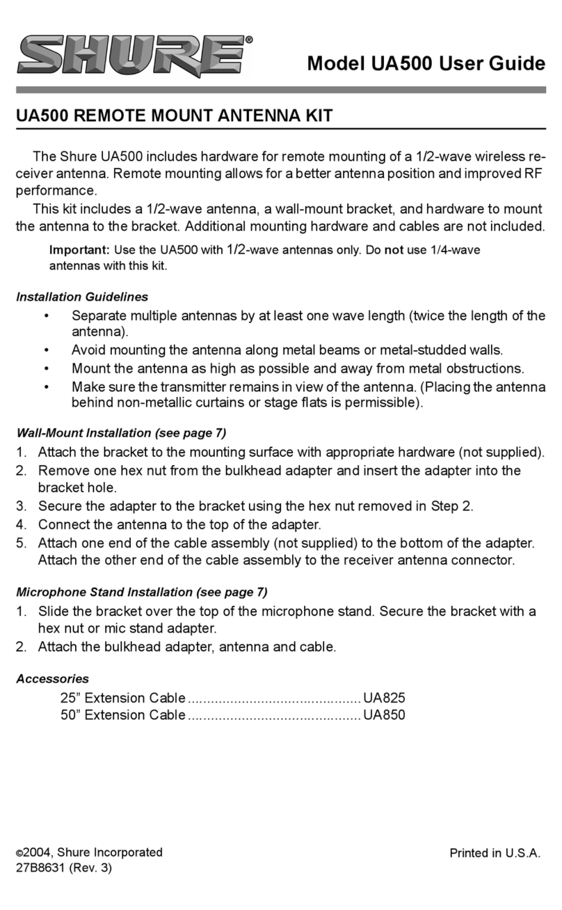
Model UA830 User Guide
SHURE MODEL UA830
UHF ACTIVE REMOTE ANTENNA KIT
SHURE MODÈLE UA830
KIT D’ANTENNE UHF ACTIVE À DISTANCE
SHURE MODELL UA830
UHF FERNAKTIVANTENNEN–KIT
MODELO UA830 DE SHURE
JUEGO DE ANTENA REMOTA ACTIVA UHF
MODELLO UA830 SHURE
KIT UA830 PER ANTENNA REMOTA ATTIVA IN UHF
27A8643(SA) Printed in U.S.A.
E1998, Shure Brothers Inc.
www.audiovias.com
Product Information
SHURE MODEL UA830
UHF ACTIVE REMOTE ANTENNA KIT
The Shure UA830 isa low-noise, in-line antenna amplifier.
The UA830 is intended for remote-mounting antennas to a
ShureModelU4 receiverorModelUA840distributionampli-
fierin a large installation, effectively shortening the distance
from the transmitters. The unit receives power through its
output port from the Shure receiver or distribution amplifier.
When an antenna is remote-mounted, the UA830 amplifies
thereceivedradiosignalstocompensateforinsertionlossin
the coaxial cable. A gain selector switch adjusts for longer
lengths of coaxial cable.
Features
"
Compatible with the Shure Model U4 wireless micro-
phone receiver and the Shure Model UA840 Antenna
Distribution System
"
Mountable on supplied desk-/wall-mount or on a
microphone stand
"
Two-position gain selector switch to adjust for longer
coaxial cable lengths (3 dB position for cables under 7
1
/
2
m [25 ft], 10 dB position for cables over 7
1
/
2
m [25
ft])
"
Isolates antennas from cable interactions
"
Extremely durable under the heaviest use
"
Shure quality, ruggedness, and reliability
INSTALLATION
1. Thread the Shure Model UA830 unit on the supplied
stand (Figure 1), or on a 5/8in.-27 thread microphone
stand.
1.
2.
TO ANTENNA
ATTACHING THE BASE AND ANTENNA
FIGURE 1
2. Connect the antenna to the TO ANTENNA port on the
Model UA830 unit (Figure 1).
3. Using50 Ωlow-losscoaxialcable(purchasedseparate-
ly, Shure UA825 or UA850 recommended), connect the
TORECEIVERportoftheUA830totheShureModelU4
wireless receiver or UA840 Antenna Distribution Sys-
tem (Figure 2).
4. IfasecondUA830LineAmplifierisneededforextreme-
ly long cable runs (over 15 m [50 ft]), repeat steps 1 to
3. See
Adjusting for Different Cable Lengths
.
U4 WIRELESS
RECEIVER
3.
TO RECEIVER
ANTENNA IN
WALL MOUNTED
MIC-STAND MOUNTED
CONNECTING THE RECEIVER
FIGURE 2
APPLICATION (FIGURE 3)
Techniqueswillvaryfromsetupto setupaccordingto different
situations. Usually, the antennas should be as farapart aspos-
sible,creatingthe widestRFfield andensuring signalreception.
In a diversity system such as the Shure Model U4, as in the ex-
amplein Figure3,Shurerecommendsthatthetwoantennasbe
positioned at 45°angles pointing away from each other(Figure
3). This way, the system is guaranteed the widest possible RF
field, minimizing the chance of the RF signal dropping out. As
a general recommendation, positioning should be tested and
adjusted for each individual setup.
45_
SHURE MODEL U4 (OR MODEL UA840)
IN A DIVERSITY SYSTEM
FIGURE 3
4 5
www.audiovias.com
ADJUSTING FOR DIFFERENT CABLE LENGTHS
(FIGURE 4)
ADJUSTING FOR DIFFERENT CABLE LENGTHS
FIGURE 4
The longer the coaxial cable connecting the UA830 unit and
thereceiverordistribution amplifier,thegreaterthe possibilityfor
signal loss. The UA830 comes with a GAIN switch that can
compensate for signal loss in longer cables. Shure recom-
mends using the Shure UA825 or UA850 coaxial cable when
remote mounting antennas. NOTE: Use only 50 Ωlow-loss
cables (RG-8 or equivalent).
Set the switch according to these guidelines:
"
UA825 Extension Cable (7.6 m [25 ft])
—Set GAIN switch
in 3 dB position.
"
UA850ExtensionCable(15.2m[50ft])
—SetGAINswitch
in 10 dB position.
"If over 15.2 m (50 ft) is required, a maximum of two
UA830’s may be chained together. Simply connect
coaxial cable from theU4 or UA840to the TORECEIVER
portofthefirstUA830,thenrunanothercoaxialcablefrom
the TO ANTENNA port of the first UA830 to the TO
RECEIVER port of the second UA830. Connect the
antenna to the TO ANTENNA port of the second UA830.
See Figure 5. TheGain switches foreach UA830 mustbe
adjusted separately. No more than two may be chained.
TO ANTENNA
INPUT
TO ANTENNA TO RECEIVER
CHAINING TWO UA830’S
FIGURE 5
*To maintain Shure UA825 and UA850 cables in top condition in
permanentinstallations:
1. Avoid sharp bends or kinks in the cables.
2. Do not deform cables with makeshift clamps, such as bending
a nail over the cable.
3. Donotusecables in permanent outdoor installations
4. Do not expose cables to extreme moisture
SPECIFICATIONS
RF Frequency Range
UA830A 782–810 MHz. . . . . . . . . . . . . . . . . . . . . . .
UA830B 854–862 MHz. . . . . . . . . . . . . . . . . . . . . . .
UA830C 800–830 MHz. . . . . . . . . . . . . . . . . . . . . . .
UA830D 774–782 MHz. . . . . . . . . . . . . . . . . . . . . . .
Power Consumption (12 Vdc)
1.0 W ±0.3 W
Signal Gain
Gain switch at 3 dB: 3.5 dB ±2.0 dB
Gain switch at 10 dB: 10 ±2.0 dB
Input/Output VSWR
Less than 2.0:1
Third Order Intercept Point (3 OIP)
More than 30 dBm
Connectors
Female, BNC-type
Dimensions (without accessories)
66.7 mm high x 31.75 mm wide x112mmdeep (2.625
x 1.250 x 4.40 inches), 108 mm (4.25 in.) high
w/mounting stand
Case
Aluminum die-casting, black painted
Swivel Adapter
Positive-action, break-resistant, adjustable from 0°to
90°, with standard 5/8in.-27 thread
Net Weight (without cable)
Without mounting stand: 0.28 kg (9.8 oz)
With mounting stand: 0.42 kg (14.8 oz)
OPTIONAL ACCESSORIES
1/2-Wave Antenna UA820A
. . . . . . . . . . . . . . . . . . . . . . .
Antenna Distribution System UA840*. . . . . . . . . . . . . . . . .
7.6 m (25 ft) Antenna Extension Cable UA825. . . . . . . . .
15.2 m (50 ft) Antenna Extension Cable UA850. . . . . . . .
*Requestcompatible frequency range
REPLACEMENT PARTS
Mounting Base A13HDB
. . . . . . . . . . . . . . . . . . . . . . . . . .
For additional service or parts information, please contact
Shure’s Service department at 1-800-516-2525. Outside the
United States, please contact your authorized Shure Service
Center.
CERTIFICATION
UA830: Eligible for CE Marking; EMC Approved under
ETS 300 445
6 7
www.audiovias.com

This manual suits for next models

5

Other Shure Antenna manuals

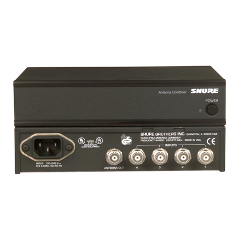
Shure PSM PA760 User manual

Shure

Shure PSM PA760 User manual

Shure UA864 User manual

Shure

Shure UA864 User manual

Shure PA421A User manual

Shure

Shure PA421A User manual

Shure PA411 User manual

Shure

Shure PA411 User manual

Shure UA844SWB User manual

Shure

Shure UA844SWB User manual

Shure UA870 User manual

Shure

Shure UA870 User manual

Shure PA421A User manual

Shure

Shure PA421A User manual

Shure PA805DB-RSMA Technical manual

Shure

Shure PA805DB-RSMA Technical manual

Shure PSM PA821SWB User manual

Shure

Shure PSM PA821SWB User manual

Shure PA805 Series User manual

Shure

Shure PA805 Series User manual

Shure AXIENT AXT630 User manual

Shure

Shure AXIENT AXT630 User manual

Shure PA705 User manual

Shure

Shure PA705 User manual

Shure PA411 User manual

Shure

Shure PA411 User manual

Shure WA490 User manual

Shure

Shure WA490 User manual

Shure UA860SWB User manual

Shure

Shure UA860SWB User manual

Shure UA844+Z18 User manual

Shure

Shure UA844+Z18 User manual

Shure UA860WB User manual

Shure

Shure UA860WB User manual

Shure UA845 User manual

Shure

Shure UA845 User manual

Shure UA864 User manual

Shure

Shure UA864 User manual

Shure WA503 User manual

Shure

Shure WA503 User manual

Shure UA844SWB User manual

Shure

Shure UA844SWB User manual

Shure UA860SWB User manual

Shure

Shure UA860SWB User manual

Shure UA845 User manual

Shure

Shure UA845 User manual

Shure PA821A User manual

Shure

Shure PA821A User manual

Popular Antenna manuals by other brands

Tru-Test XRP-1 user manual

Tru-Test

Tru-Test XRP-1 user manual

ALLIANCE U-100 Service manual

ALLIANCE

ALLIANCE U-100 Service manual

TRENDnet TEW-OA14DK Quick installation guide

TRENDnet

TRENDnet TEW-OA14DK Quick installation guide

Greentek E2169TG1730N installation manual

Greentek

Greentek E2169TG1730N installation manual

JMA Wireless SV02UTS136-PT installation guide

JMA Wireless

JMA Wireless SV02UTS136-PT installation guide

Sea Tel ST88-21 C/Ku-Band TVRO Installation and operation manual

Sea Tel

Sea Tel ST88-21 C/Ku-Band TVRO Installation and operation manual

Antares ANTARION G6+ CONNECT installation manual

Antares

Antares ANTARION G6+ CONNECT installation manual

Cisco AIR-ANT2451NV-R Technical guide

Cisco

Cisco AIR-ANT2451NV-R Technical guide

Diamond Antenna X500HNA Operation instructions

Diamond Antenna

Diamond Antenna X500HNA Operation instructions

Electro-Voice LPA500 owner's manual

Electro-Voice

Electro-Voice LPA500 owner's manual

Simrad TV45 manual

Simrad

Simrad TV45 manual

CPI 1194 Series Assembly manual

CPI

CPI 1194 Series Assembly manual

Fracarro TAU11 quick start guide

Fracarro

Fracarro TAU11 quick start guide

Telex ALP-600 instruction manual

Telex

Telex ALP-600 instruction manual

TRENDnet TEW-AI75O Specifications

TRENDnet

TRENDnet TEW-AI75O Specifications

Valcom AS-3772B/U Technical manual

Valcom

Valcom AS-3772B/U Technical manual

H3C ANT-5010Y Yagi manual

H3C

H3C ANT-5010Y Yagi manual

Sirius XM RAdio XMPT-MA installation guide

Sirius XM RAdio

Sirius XM RAdio XMPT-MA installation guide

manuals.online logo
manuals.online logoBrands
  • About & Mission
  • Contact us
  • Privacy Policy
  • Terms and Conditions

Copyright 2025 Manuals.Online. All Rights Reserved.