About the R&S TSMS-OMN70
R&S®TSMS-OMN70
5Installation Instructions 1179.7291.02 ─ 01
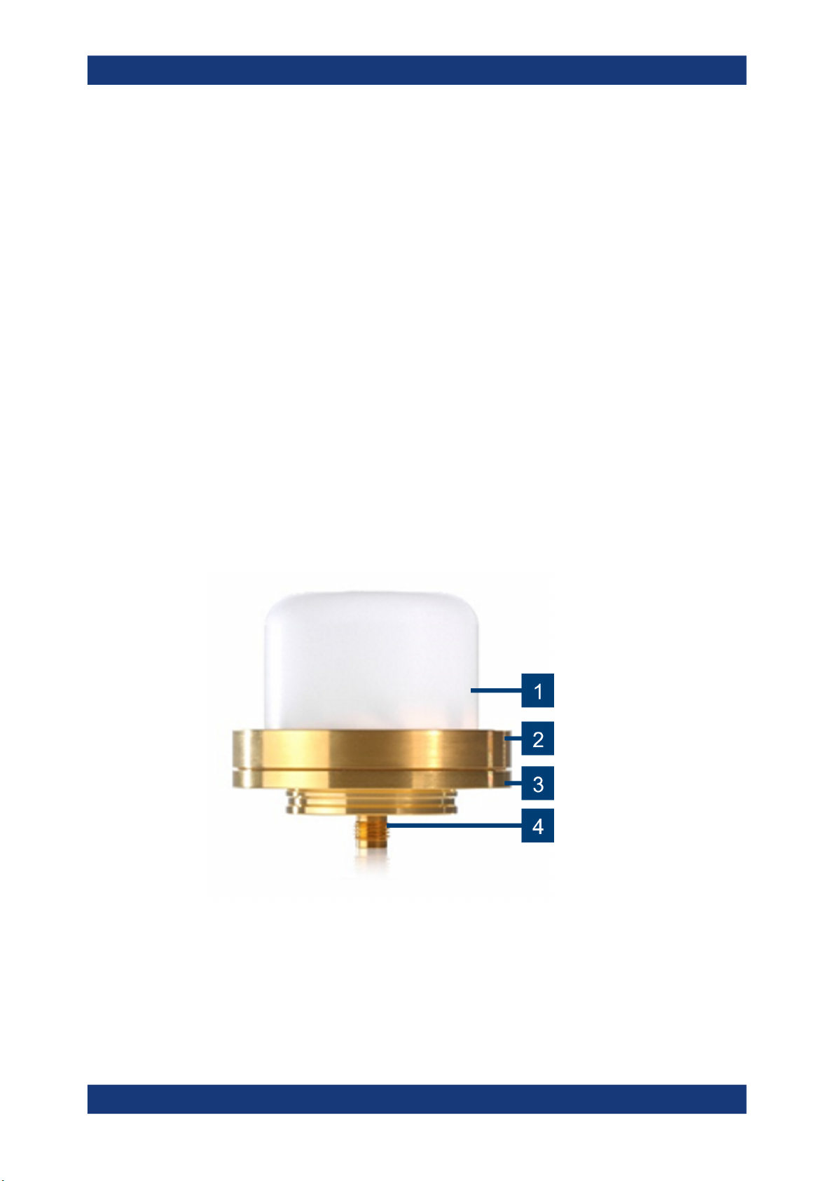
1 About the R&S TSMS-OMN70
The R&S TSMS-OMN70 is a super wideband omnidirectional antenna for mm-wave
frequency range that fits for all use-cases of the R&S TSMS53DC super wideband
ultra compact downconverter. The frequency rage of the R&S TSMS-OMN70 is wide.
The antenna can be used:
●Between 4.5 GHz and 70 GHz with medium RF parameters (out of band)
●Between 17 GHz and 53 GHz with optimal RF parameters (in band).
The antenna pattern is optimized for drive- and walk-testing with transmitters on a typi-
cal base station height over ground. When looking at the vertical pattern, the gain max-
imum is about 30 degrees to 60 degrees above the horizon, while the horizontal pat-
tern remains omnidirectional. For details, see the data sheet.
Intended use
The R&S TSMS-OMN70 antenna is designed for connection to the R&S TSMS53DC
downconverter. The antenna is optimized for drive and walking testing for 5G FR2
bands and possible future 6G bands. It can be carried in a bag or mounted on a holder.
Observe the operating conditions and performance limits listed in the data sheet.
Target audience
This document targets technicians, operators and maintenance personnel from net-
work operators, testing service providers, infrastructure vendors. The required skills
and experience depend on the application of the product.
Safety information in the documentation
Safety information warns you of potential dangers and gives instructions on how to pre-
vent personal injury or damage caused by dangerous situations. Throughout the docu-
mentation, safety instructions are provided when you need to take care during setup or
operation.
The documentation helps you use the R&S TSMS-OMN70 safely and efficiently. Keep
the documentation nearby and offer it to other users.
Related manuals
This manual describes the installation of the R&S TSMS-OMN70. For information on
all other topics, refer to the following manuals:
●User manual of the R&S TSMS53DC
For information on maintenance, transport and disposal, refer to the R&S TSMS53DC
user manual.