Outlaw LCR User manual

Owner’s Manual
The Outlaw LCR
Left/Center/Right Channel
Loudspeakers
available in Black and Cherry
Version 1.0

2
Outlaw Audio
Owner’s Manual
For Future Reference
Record your LCR Loudspeaker serial number and date of purchase here. It is found on the
back panel.
Model Number
Serial Number
Date of Purchase
The contents of this manual are Copyright © 2007 by Outlaw Audio, LLC, and may not be
duplicated or reproduced by any means, whether physical, electronic or otherwise without prior
written consent from Outlaw Audio.
Outlaw Audio and the Outlaw Audio logo are registered trademarks of Outlaw Audio, LLC.
Any trademark not acknowledged is recognized as the property of the respective owner.
Specifications are those in effect at the time of printing. Outlaw Audio reserves the right to
change specifications or designs at any time without notice or liability to modify or upgrade
units previously sold.
Table of Contents
The Outlaw LCR
Left/Center/Right Channel
Loudspeakers
available in Black and Cherry
Congratulations on your purchase of our Outlaw Audio LCR (Left/Center/Right
Channel Loudspeakers). You now own one of the most advanced LCR speakers
available. The Outlaw LCR Channel Loudspeakers provide remarkable
performance in their price range. True to even the most demanding source
material, your new Outlaw LCRs won’t skip a beat.
After a brief “break-in” period you’ll discover a sound that maintains its image
regardless of where you are in the room, a natural timbre that sustains the
important midrange integrity of the very best recordings and a level of flexibility
unrivaled in other LCR style speakers.
More important is the Outlaw LCRs industry exclusive MCO (Main/Center Opti-
mization) crossover technology that enables the user to customize the LCRs for
either center channel (horizontal) or main channel (vertical) placement. The
MCO circuit can also be engaged to provide an “electrical height adjustment”
for vertical on-wall speaker mounts!
This is all accomplished here in the United States through precision engineer-
ing and meticulous manufacturing standards. From our custom designed
tweeter, built with Scandinavian parts, to 100% film capacitors, the Outlaw
LCR design and assembly take nothing for granted. In the manufacturing
process every Outlaw speaker is measured and calibrated to
match our reference design plus or minus ½ dB. This means your
pair of speakers will be virtually identical; a standard that is only found in the
world’s finest loudspeakers.
The many features of the Outlaw LCRs include:
nA custom designed 25mm soft dome tweeter with copper cap, vented former,
Ferro fluid cooling and a full video shield and bucking magnet to virtually
eliminate any stray magnetic forces.
n2 long throw 5-1/4" Seas woofers for deep, controlled bass extension.
nFurniture grade cabinetry including veneers for cherry finish and high-
quality hand-painted black finish on pan fiber.
nTrue Bi-amp/Bi-wire design using precision five-way binding posts with
separate crossovers for woofer and tweeter.
nA proprietary 3-position Boundary Compensation switch for wall and corner
placement.
nA proprietary 3-position High Frequency switch to compensate for either
heavily dampened or live rooms.
nA proprietary 2-position Center/Main (L/R) Configuration switch to select
speaker orientation.
nOptional
Low-profile brackets for easy horizontal or vertical wall-mounting.
We encourage you to carefully follow the setup information provided in the
following pages to ensure you get every last note of audiophile performance
from your new speakers.
Table of Contents
2 The Outlaw LCR Left/Center/Right Channel
Loudspeakers
3 Unpacking
3 Accessories
3 The LCR Controls and Connections
3 Setup Guide
3Connecting To Your System
3Preparing the Speaker Wire for Installation
3LCR Loudspeaker Rear Panel
4Speaker Connection Precautions
4Option 1: Connecting to a system with a standard single speaker wire.
5Option 2: Connecting to a system in a bi-wire scheme.
6Option 3: Connecting to a system in a bi-amplify scheme.
7 Notes on Speaker Placement
7L/R Mode (Vertical Placement)
7Center Channel Mode (Horizontal Placement)
7 Setting the Outlaw LCR’s Controls
7Boundary Compensation Switch
7High Frequency Switch
8Center/Main (L/R) Configuration Switch
9 External System Adjustments
9 Crossovers for Use with Powered Subwoofers
9 Volume Level
9 Surround Sound Considerations
9 Care of Your Speakers
9 Troubleshooting
10 Specifications
11 The Outlaw Audio 30-Day Satisfaction Guarantee
11 Outlaw Audio Limited Warranty

3
The Outlaw LCR Channel Loudspeakers
Owner’s Manual
Setup Guide
Unpacking
The carton and packing materials used in shipping your new speakers were
specially designed to cushion it from the shocks and vibrations of shipping. We
strongly suggest that you save the carton and packing materials to use if you
move, or if the unit needs to be shipped back to us for any reason.
To minimize the size of the carton in storage, you may wish to flatten it by
carefully opening the top and bottom flaps and folding the carton flat. Pack-
ing materials that cannot be collapsed should be saved along with the carton
in a plastic bag.
Accessories
After unpacking the LCR please confirm that the following accessories have
been included.
n1 Black Metal Grill (pre-installed)
nOwner’s Manual
If any of the above is missing from your shipment, please contact Outlaw Audio
immediately at 866-OUTLAWS.
The LCR Controls and Connections
ABoundary Switch
This three-position switch provides a (0dB, 2dB and 4dB) reduction in
upper bass frequencies to maintain a linear response for wall or corner
loaded speaker placements.
BHigh Frequency Speaker Binding Posts
Speaker level inputs; connect amplifier to these or low frequency terminals.
CLow Frequency Speaker Binding Posts
Speaker level inputs; connect amplifier to these or high frequency terminals.
DCenter/Main (L/R) Speaker Configuration Switch
This two-position switch adjusts speaker for mode of operation (i.e. Left/
Right speaker Placement or Horizontal Center Channel placement).
EHigh Frequency Switch
This three-position switch provides a (-2dB, 0dB, +2dB) treble compensa-
tion for bright or heavily dampened listening environments.
FBinding Post Jumpers
These connect the two pairs of binding posts and should remain installed
unless using a bi-wire or bi-amplify connection scheme.
Setup Guide
Connecting To Your System
To get the maximum performance from your new Outlaw LCR system it must be
correctly connected,positioned properlywithintheroom andconfiguredtomatch
yourlisteningenvironment.There arethreeprimaryconnectionstylescompatible
with your Outlaw LCRs. These include the standard one wire (per) speaker con-
nection, bi-wiring which uses either a pair of speaker wires or a custom bi-wire
cable and a single amplifier channel per speaker, or bi-amplifying which uses
two speaker wires and two power amplifiers per speaker.
Preparing the Speaker Wire for Installation
High qualityspeaker wiresare essentialforoptimalperformance.Werecommend
the use of a heavy gauge (16 or heavier) oxygen-free, multi-stranded copper wire.
For lengths over 25 feet, a heavier gauge of wire should be used; as with other
gauge based conductors, the lower the number the heavier the gauge.
When purchasing wire, look for cabling that clearly marks polarity on one
conductor. Often speaker wire manufacturers will use a single solid line or their
logo on one side for this purpose. This will make connections easier later on.
Most installers consider the marked conductor their “positive” lead.
Since your Outlaw LCR offer true five-way binding posts, you can use speaker
wires that have terminated ends such as banana plugs, spades, or pins. When
using spades, they must be compatible with the larger 5/16" posts.
To prepare your non-terminated wire for installation, you will need
to perform the following tasks:
1. Split each end of the speaker wire in half leaving approximately two
inches of “separate conductors” as shown below.
2. Remove a 1/2" of insulation from each conductor, also shown below.
3. Separately twist each stranded wire together ensuring that all four
leads are kept apart.
Boundary
Comp Cong
Ctr
L/R
High
Freq
0dB
-2dB
-4dB
+2dB
0dB
-2dB
LCR Loudspeaker Rear Panel
E
F
B
A
C
D
1/2" 2"

4
Outlaw Audio
Owner’s Manual
Setup Guide
Option 1:
Connecting to a system with a standard single
speaker wire.
This is the most common way to connect an individual speaker to a power
amplifier or receiver. A standard 16-gauge speaker wire is used to join the amp
and speaker together.
To connect an individual speaker with a single speaker wire, carefully
follow the steps below:
1. Turn off all system components and unplug the receiver or
amplifier.
2. Loosen one set of the Outlaw LCR binding posts.
NOTE: Be sure that the binding posts jumpers remain installed.
3. Insert the appropriate polarity wire through the postholes on the
binding post.
4. Carefully tighten the binding post until snug. Over tightening will
strip the binding post and prevent a solid connection.
5. Repeat steps 2-4 at the amplifier binding post with the opposite end
of the speaker wire.
Speaker Connection Precautions
When using one of the following options to wire your Outlaw LCR Loudspeakers
to your amplifier/receiver, please be sure that you take the following precautions
before and after making the connections.
POWER OFF
To prevent damage to your amplifier or speakers and avoid the risk of
electrical shock always disconnect the power to your receiver or amplifier
when making any system connections.
MAINTAIN POLARITY
Remember that polarity must be maintained between speaker and
amplifier, ie. positive terminal (red post) on speaker to positive terminal
on power amplifier.
PREVENT SHORTS
Check terminal posts on both connections (speaker and amplifier) to
ensure that loose copper strands have not been allowed to “short” the
binding post pairs. Any loose strands that touch both the positive and
negative terminal posts must be removed before powering up the ampli-
fier. Failure to do so may result in damage to the amplifier or speaker.
CTRLEFT RIGHT
Boundary
Comp Cong
Ctr
L/R
High
Freq
0dB
-2dB
-4dB
+2dB
0dB
-2dB
Boundary
Comp Cong
Ctr
L/R
High
Freq
0dB
-2dB
-4dB
+2dB
0dB
-2dB
Boundary
Comp Cong
Ctr
L/R
High
Freq
0dB
-2dB
-4dB
+2dB
0dB
-2dB
Option 1: Standard Connection
Left Speaker Right Speaker
Receiver/Amplifier
Center Speaker
Jumpers
remain in
place
Jumpers
remain in
place

5
The Outlaw LCR Channel Loudspeakers
Owner’s Manual
Setup Guide
Option 2:
Connecting to a system in a bi-wire scheme.
Some audiophiles prefer to use a bi-wire scheme when connecting their speakers
and amplifiers. While this connection type does not provide the added power of
a bi-amplified wiring scheme, described in the next section, it can be beneficial
in reducing the amount of EMF (electromotive force) that the woofer generates
on the more “voltage-sensitive” high frequency circuitry.
To connect your speakers using the bi-wiring option, carefully follow
the steps below:
1. Turn off all system components and unplug the receiver or
amplifier.
2. Connect both pairs of speaker wire on one end by twisting the
positive (marked) copper ends together as shown below.
3. Repeat step 2 for the negative (unmarked) copper leads on the same
end of the speaker wire, also shown below.
NOTE: Some speaker wire manufacturers offer a speaker wire
specifically designed for bi-wire applications. With these wires, Steps
2 and 3 are unnecessary.
4. Loosen your receiver or amplifier’s corresponding binding posts.
5. Insert the appropriate polarity wire through the postholes on the
amplifier’s binding post.
Be sure to use the “double speaker wire” connection you have just
created. The opposite end of this wire will have four leads, a pair for
each set of speaker binding posts.
6. Carefully tighten the binding post until snug. Over tightening will
strip the binding post and prevent a solid connection.
7. Loosen both sets of the Outlaw LCR’s binding posts.
8. Remove both binding posts jumpers.
CAUTION: Failure to remove these jumpers using this connec-
tion scheme will result in damage to your power amplifier and or
speakers.
9. Select one speaker wire lead to connect to the high frequency binding
posts.
10. Insert the appropriate polarity wire through the postholes on the
binding post.
11. Carefully tighten the binding post until snug. Over tightening will
strip the binding post and prevent a solid connection.
12. Repeat steps 9-11 for the low frequency binding posts.
CTRLEFT RIGHT
Boundary
Comp Cong
Ctr
L/R
High
Freq
0dB
-2dB
-4dB
+2dB
0dB
-2dB
Boundary
Comp Cong
Ctr
L/R
High
Freq
0dB
-2dB
-4dB
+2dB
0dB
-2dB
Boundary
Comp Cong
Ctr
L/R
High
Freq
0dB
-2dB
-4dB
+2dB
0dB
-2dB
Left Speaker Right Speaker
Receiver/Amplifier
Center Speaker
Jumpers
removed
Jumpers
removed
Option 2: Bi-Wired Connection

6
Outlaw Audio
Owner’s Manual
Setup Guide
Option 3:
Connecting to a system in a bi-amplify scheme.
Like the bi-wire scheme described on the previous page, a bi-amplified wiring
schemedoesreducetheamountof EMFonthespeaker’s high frequency circuitry.
However,inabi-amplifiedwiringscheme,theuserprovidesseparateamplification
for both sections (high frequencies and low frequencies) of the speaker.
Some audiophiles tend to prefer this method of connectivity as it ensures that
the more “power hungry” woofers are not limited by the additional power
demands of the high frequency portion of the speaker while still maintaining
the EMF benefits of a bi-wire scheme.
NOTE: In a bi-amplify scheme, it is necessary to use matching amplifiers
for both high frequency and low frequency connections, otherwise an
imbalance will occur between each portion of the speaker. This imbalance
will negatively impact performance. Also, using the “A +B” terminals on a
receiver does not offer an improved connection over using a single speaker
wire from the “A” terminals. Separate amplifier channels are required to
receive the benefits of bi-amplification.
1. Turn off all system components and unplug the receiver/pre-amp
and amplifiers.
2. Connect a Y-adapter to the corresponding pre-amp output on your
processor.
3. Connect the two amplifier channels you intend to use, one to each
of the two outputs the Y-adapter has created.
4. Loosen the corresponding binding posts on the power amplifier you
plan to use for the high frequency portion of your Outlaw LCR.
5. Insert the appropriate polarity wire through the postholes on the
amplifier’s binding post.
6. Carefully tighten the binding post until snug. Over tightening will
strip the binding post and prevent a solid connection.
7. Repeat steps 3-6 for the power amplifier you intend to use to drive
the low frequency portion of your Outlaw LCR.
8. Loosen both sets of the LCR’s binding posts.
9. Remove both binding post jumpers.
CAUTION: Failure to remove these jumpers using this connec-
tion scheme will result in damage to your power amplifier and or
speakers.
10. Connect your “high frequency” amplifier to the high frequency binding
posts on your Outlaw LCR by inserting the appropriate polarity wires
through the postholes on the binding post.
11. Carefully tighten the binding posts until snug. Over tightening will
strip the binding post and prevent a solid connection.
12. Repeat steps 10-11 for the low frequency portion of your Outlaw
LCR.
LEFT
PRE OUT CENTER RIGHT
INPUTINPUTINPUTINPUT
INPUTINPUT
Boundary
Comp Cong
Ctr
L/R
High
Freq
0dB
-2dB
-4dB
+2dB
0dB
-2dB
Boundary
Comp Cong
Ctr
L/R
High
Freq
0dB
-2dB
-4dB
+2dB
0dB
-2dB
Boundary
Comp Cong
Ctr
L/R
High
Freq
0dB
-2dB
-4dB
+2dB
0dB
-2dB
Option 3: Bi-Amplified Connection
Left Speaker Right Speaker
Receiver/
Pre-Amp/
Processor
Amplifiers
Jumpers
removed
Center Speaker
Jumpers
removed

7
The Outlaw LCR Channel Loudspeakers
Owner’s Manual
Setting the Outlaw LCR’s Controls
Notes on Speaker Placement
The following suggestions should be adhered to as closely as possible. While
each listening room imparts its own sonic compromises, these guidelines will
help you achieve the greatest performance from your Outlaw LCR system. The
decisions you make regarding the placement of the speakers will impact the
orientation and control settings of the LCRs as well. Also, if wall mounting your
LCRs, optional mounting brackets are available from Outlaw Audio.
L/R Mode (Vertical Placement)
n Placing your speakers at equal distances from the listening position, thus
creating an “equilateral” triangle, will help create an optimal stereo
imaging environment. See diagram below.
n Soundstage is directly affected by “toe-in”. Pointing the Outlaw LCR directly
at the “sweet spot” creates the most accurate soundstage. See diagram
below.
However, room anomalies may require that a speaker be toed further in
or out. Toeing a speaker out (adjusting the angle of the speaker outward
including straight forward) will widen your soundstage. The opposite will
occur when toeing a speaker in.
n Ideal tweeter height in the L/R Channel position is 39 inches.
n Proximity to walls and corners will increase lower frequency output. When
placed too close this additional lower frequency output may sound un-
natural or bloated. Whenever possible place your speakers no closer than
two feet to the nearest wall.
NOTE: When wall mounted in a vertical array where the tweeter height
is greater than 57 inches, follow the recommendations outlined in the
Center/Main (L/R) Configuration Switch section.
Center Channel Mode (Horizontal Placement)
n Center channel speaker should be placed directly above or below the moni-
tor/display to ensure soundtrack dialog remains anchored to on-screen
information.
n Ideal tweeter height in the Center Channel position is 39 inches.
Setting the Outlaw LCR’s Controls
Boundary Compensation Switch
Depending on the proximity of your Outlaw LCR to a
wall or corner, you may find that certain upper bass
frequencies sound “boomy”. At these critical frequen-
cies, this added energy manifests itself as ”chestiness”
particularly in male voices. To compensate for these
compromised, but often-necessary speaker placements,
the Outlaw LCR provides a custom Boundary Compensation Circuit.
While other manufacturers have recognized the importance of boundary
compensation circuitry, they often fall short in their implementation opting for
a single “averaged” adjustment for all non-ideal speaker placements.
After carefully calculating the effects of wall proximity and corner loading on
the Outlaw LCR, we have integrated a no-compromise Boundary Compensation
Circuit that includes different settings for each of the major speaker placement
locations. These are:
n
Open air placement
The speaker is more than 24 inches away from all walls.
n Single wall placement
The speaker is within 24 inches of a single wall.
n Corner placement
The speaker is located within 24 inches of two walls.
The available settings allow you to tailor the behavior of your Outlaw LCR for
optimal performance under most listening room conditions. Using the following
guidelines, adjust each speaker according to its individual environment. Keep
in mind that this setting can and should vary by speaker when necessary.
When the Outlaw LCR is no closer than 24 inches to any wall; the Boundary
switch should be set to “0”. If the Outlaw LCR is with 24” of a single wall, set
the Boundary switch to “-2dB”. If the Outlaw LCR is corner loaded (within 24
inches of two different walls), use the “-4dB” boundary switch position.
High Frequency Switch
Each room imparts its own sonic signature to the
signal that arrives at the listening position. In rooms
with minimal wall treatments, significant glass (ie a
large number of windows), hardwood or tile floors the
resulting sound may have an overemphasized high
frequency response. This is typically characterized as
a slight edginess that may present itself in the form of listening fatigue. In
these listening environments we recommend using the “-2dB” position on the
Outlaw LCR High Frequency switch.
In overly dampened rooms with wall-to-wall carpets, extensive absorptive
wall coverings, acoustic panels etc. you may find the high frequency response
lacking. This could be observed as a dull or less detailed performance. In these
listening environments we recommend selecting the “+2dB” position on the
Outlaw LCR High Frequency switch.
Since most listening rooms are fairly well balanced, with a mix of dampening
and reflective surfaces the “0dB” position will be optimal for the majority of
users.
Boundary
Comp Cong
Ctr
L/R
High
Freq
0dB
-2dB
-4dB
+2dB
0dB
-2dB
Boundary
Comp Cong
Ctr
L/R
High
Freq
0dB
-2dB
-4dB
+2dB
0dB
-2dB
Ideal tweeter height is
39 inches from floor

8
Outlaw Audio
Owner’s Manual
Center/Main (L/R) Configuration Switch
However, when wall mounted in a vertical array where the tweeter is mounted
substantially above the normal 39-inch tweeter-height recommendation,
place the Center/Main Configuration Switch in the “Center” position. This
will shift the listening axis down towards the listener, resulting in a natural
full sounding reproduction.
The Outlaw LCR has been designed to work in a variety of listening environ-
ments. In many cases, ideal speaker height is not possible, so we’ve included a
proprietary crossover technology that acts as an electronic height adjustment
to compensate for these situations. When used in conjunction with the recom-
mendations shown in the Orientation diagram below, this MCO (Main/Center
Optimization) circuitry enables your LCRs to perform at their best in almost
any room situation.
Boundary
Comp Cong
Ctr
L/R
High
Freq
0dB
-2dB
-4dB
+2dB
0dB
-2dB
Setting the Outlaw LCR’s Controls
Boundary
Comp Cong
Ctr
L/R
High
Freq
0dB
-2dB
-4dB
+2dB
0dB
-2dB
This switch optimizes your Outlaw LCRs crossover
depending upon its in-room orientation (horizontal or
vertical placement). When the Outlaw LCR is used as a
horizontal-oriented center channel, place the Center/
Main Configuration Switch in the “Center” position.
If your Outlaw LCR is being used in a vertical configura-
tion with a tweeter height of approximately 39 inches,
place the Center/Main Configuration Switch in the
“L/R” position. This will ensure a midrange sound that remains focused
straight ahead.
LCR Speaker Orientation
Use the Outlaw Audio logo above the
Connection Cup on the rear panel of
your Outlaw LCR to determine the correct
orientation of your speakers. Following the
guidelines below will yield the best sonic
results in most situations.
39 in.
57 in.
If you will be placing
your LCR speaker so
that the tweeters are
57 inches or higher
above the floor, orient
them as shown at left.
If you will be
placing your LCR speaker so
that the tweeters are less than
57 inches above the floor,
orient them as shown here.
Remember, 39 inches is the
ideal tweeter height.

9
The Outlaw LCR Channel Loudspeakers
Owner’s Manual
External System Adjustments
Crossovers for Use with Powered Subwoofers
The Outlaw LCRs have fairly good low frequency output. As a standalone speaker
they will provide a neutral “true-to-source” reproduction of your audiophile
grade recordings. But for those seeking that last 2 octaves of audibility you may
wish to consider the addition of a powered subwoofer. Proper integration of sub
and speaker begins with the careful selection of the crossover.
Some receivers and processors supply a series of crossover options to integrate
your subwoofer. If you are using an Outlaw processor or receiver
the optimal setting is 80Hz.
For other systems, you will need to consider the Outlaw LCR’s +/-3dB down
point of 75 HZ. Based upon the prevailing use of symmetrical fourth order
networks in receivers and processors we suggest choosing the closest crossover
point provided by your system that is equal to or greater than 80Hz.
Volume Level
When available, match the levels of all of your speakers, including the Outlaw
LCR, as described in your receiver or processor owner's manual. We recommend
using an SPL meter such as the Radio Shack (part number 33-2050). When
using the test tones, measure from the listening chair and set the meter to the
75 dB level. In order to accurately measure levels between channels use “C”
weighting and the “slow” setting.
Surround Sound Considerations
A great speaker has many characteristics. Most importantly, it should have a
linear response, with a large soundstage and precision imaging while at the
same time be capable of reproducing considerable dynamics without sounding
strained. If these design goals are accomplished, the speaker will be at home
both in music-only and full in-home theater systems.
With the above in mind, we offer the following advice when integrating your
Outlaw LCRs in a 5.1, 6.1 or 7.1 surround sound system.
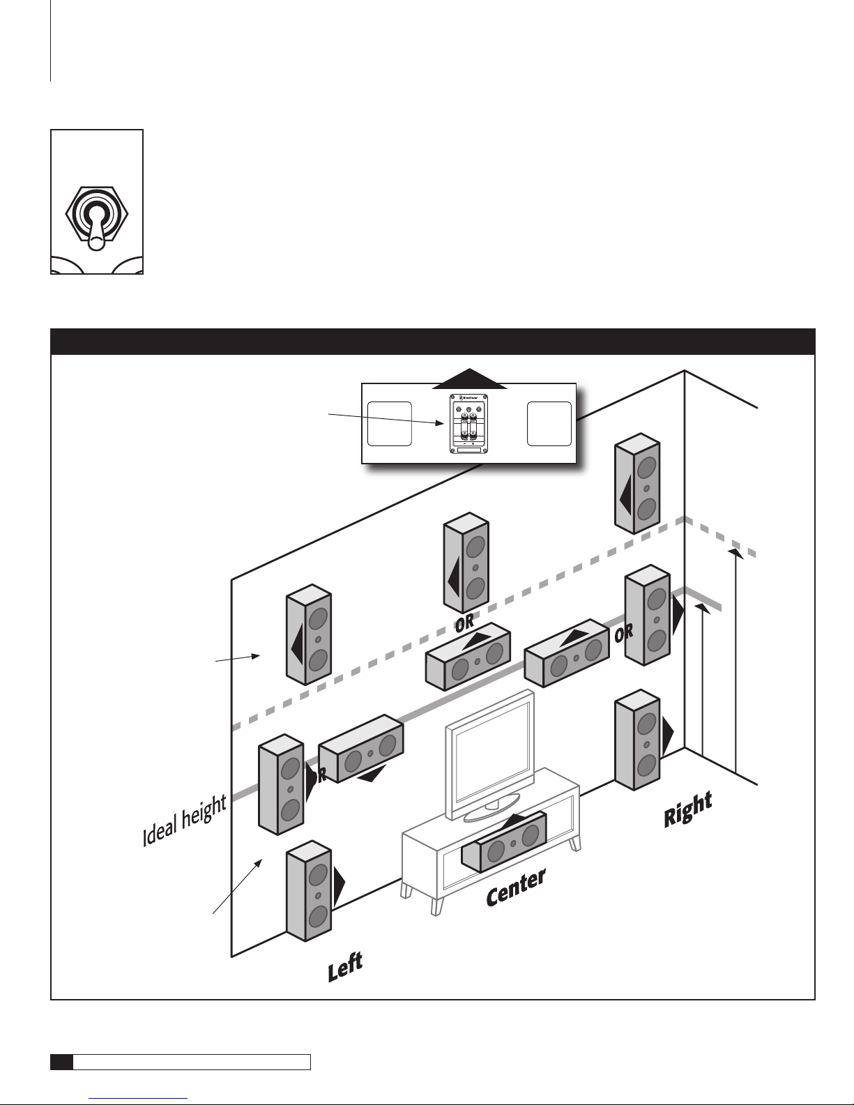
n Tweeter height should remain as close to even as possible between your
front left, center and right channel speakers. This helps maintain “timbre”
which is the characteristic of a sound that separates itself from other sounds
of the same volume level and pitch.
When a sound effect pans from one speaker to the next, you’ll want your
speakers’ timbre to match as closely as possible. This will ensure that
whatever instrument or sound effect you are hearing sounds the same,
regardless of which speaker in your system it is emanating from.
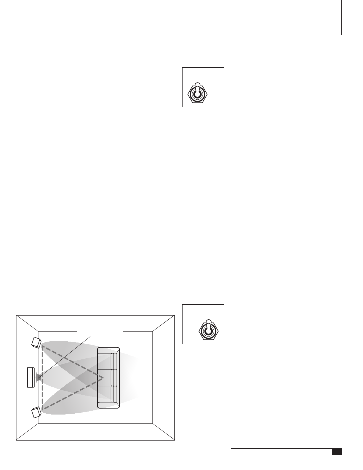
n Whenusing“directradiating”speakersliketheOutlawLCRsinthesurround
positiontheyshould beplacedjustbehindthelistening position.While timbre
remains very important, these speakers should be placed approximately 1-2
feet above the listener’s ears to create a more diffused sound field.
n Surround back channels, more commonly used in DD-EX™ and
DTS-ES™ soundtracks should be placed at the same height as the sur-
round channels. If you are using a pair of speakers in the surround back
position they should each be placed approximately 30 degrees off of the
center axis. If only a single surround back speaker is used, it should be
placed on center axis.
n Today’s blockbuster movie soundtracks take advantage of a dedicated
subwoofer channel called the LFE (Low Frequency Effects). For this
reason, we advocate the used of a powered subwoofer like our LFM series
subs. Placement of the subwoofer will depend on room acoustics, so you’ll
want to consult with your subwoofer manufacturer for tips on getting the
most from your sub. The Outlaw LFM series subwoofer manuals, which
are available as a free download at www.outlawaudio.com, all share
an excellent primer on subwoofer placement. We invite you to use that
information to maximize your system’s performance.
Care of Your Speakers
Exceptional efforts were taken during the design and manufacture of the Outlaw
LCRs so that they could provide you with a lifetime’s worth of music and movie
reproduction. Proper care along the way will ensure that they always look as
great as they sound.
We recommend using a lint-free cloth to clean your speaker’s cabinets. If
necessary you may moisten that cloth with plain water. Special care should
be taken to avoid getting water on the dome tweeter or woofer. Do not use any
other solvents or chemicals as damage may occur.
Troubleshooting
Troubleshooting
PROBLEM:
No output from the speakers
SOLUTIONS:
nCheck to ensure that your amplifier is powered on.
nCheck to make sure your source (CD, DVD etc.) is actively outputting
a signal.
nCheck to ensure speaker wires are properly connected.
PROBLEM:
Amplifier shuts down at power up or during high
volume playback
SOLUTIONS:
nCheck for a shorted speaker wire connection. This is observed as
speaker wire that touches both the positive and negative (red and
black) binding posts at the same time. This can occur at the amplifier
or the speaker’s binding posts.
nCheck to make sure your speaker wires are connected properly.
PROBLEM:
Woofer or tweeter sounds “distorted”
SOLUTIONS:
nCheck bass and treble controls and return them to flat.
nReduce volume of playback as amplifier may be “clipping”

10
Outlaw Audio
Owner’s Manual
Specifications
SENSITIVITY 90dB
RATED AMPLIFIER POWER 50-300watts
IMPEDANCE 4 Ohms
FREQUENCY RESPONSE 75Hz-22kHz
DRIVERS Tweeter 1" Custom Silk Dome designed and
manufactured with precision
Scandanavian parts
Woofer 2 x 5-1/4" SEAS Driver with Diecast Magne-
sium basket, treated paper cone, low-loss
rubber surround and 26mm CCAW voice coil.
LINEAR COIL TRAVEL 10mm p-p
BOUNDARY COMPENSATION 0dB, -2dB, -4dB starting at 400Hz where it
SWITCH plateaus at 250Hz and remains flat to
resonance
HIGH FREQUENCY SWITCH +2dB, 0dB, -2dB starting at 4kHz and peaking
at 20kHz
DIMENSIONS (HxDxW) 19" x 8-7/8" (w/ grille) x 7-1/4"
WEIGHT 20 lbs
Specifications

11
The Outlaw LCR Channel Loudspeakers
Owner’s Manual
Outlaw Audio Limited Warranty
The Outlaw Audio 30-Day Satisfaction Guarantee
This product is guaranteed to satisfy all your needs for a high performance
loudspeaker system. If for any reason, you are not completely satisfied with it,
please contact us at 866-OUTLAWA (688-5292) within 30 days of receipt of
the unit and you will receive a return authorization.
Please save all of your packing material in that the speakers can get dama-
mged in shipping without proper protection. We recommend that you keep
the packing (even after 30 days) so that if you ever move, the speakers will
be adequately protected.
If you decide to return the speakers, your only cost will be the original shipping
charge. When your loudspeakers arrive, we will inspect them to insure that they
were shipped back to us in original condition. Upon satisfactory inspection, we
will issue a full credit for your original purchase price.
Outlaw Audio Limited Warranty
This warranty protects the owner of the Outlaw LCR Loudspeaker (the
PRODUCT) for five (5) years from the date of purchase.
This warranty covers all defects in material and workmanship with the
following specific exceptions. These are:
• Damage caused by improper installation or adjustment
• Damage caused by accident, unreasonable use or neglect
• Damage from failure to follow instructions contained in this
Owner’s Manual
• Damage from the performance of repairs by someone not authorized
by Outlaw Audio
• Any unit on which the serial number has been defaced, modified,
or removed
• Damage occurring during shipment
• Units which have been altered or modified in design, appearance
or construction
This warranty covers only the actual defects within the PRODUCT itself.
IT DOES NOT cover costs of installation in (or removal from) a fixed
installation, or normal set-up, claims based on any misrepresentation by
the seller, or performance variations resulting from installation related
circumstances such as signal quality, AC power or incompatibilities with
speakers and/or other system components.
During the warranty period, Outlaw Audio will, at its option, either repair
the defect, or replace the defective product, or the defective parts, or com-
ponents thereof at no charge to the owner for parts and labor covered by
this warranty. If necessary repairs are not covered by this warranty, or if
a unit is examined which is not in need of repair, you will be charged for
the repairs and/or the examination. If non-warranted repairs are needed,
we will notify you of the estimated cost and ask for your authorization to
perform said repairs.
You must pay shipping charges incurred in getting your Product to the
factory. We will pay the return shipping charges if the repairs are covered
by the warranty. Please save the original shipping cartons as the unit
MUST be returned in the original carton and packing.
(Replacement cartons are available at a modest charge.)
If your product needs service, please call Outlaw Audio Inc. at 866-OUT-
LAWA (688-5292).
You will need to present the original bill of sale to establish the date of
purchase. In the event that the proof of purchase cannot be established
with the original receipt, the warranty period shall be determined by the
earliest date of manufacture shown on the unit, provided that the serial
number label has not been altered in any manner, or by our records
relating to that serial number.
In the event that you wish to return your Outlaw speaker back to us, for
any reason, please call to arrange for a Return Authorization Number.
This will insure that your problem is discussed with a service technician
who will determine if there is a quick solution to your problem.
Outlaw Audio shall not be liable for, in any way responsible for, any inci-
dental or consequential damages of any kind. Some states do not allow
limitations on how long an implied warranty lasts and/or do not allow the
exclusion of incidental or consequential damages, therefore, the limita-
tions and exclusions stated herein may not apply to you. This warranty
gives you specific legal rights; and you may also have other rights which
vary from state to state.
THERE ARE NO WARRANTIES GIVEN BY OUTLAW AUDIO WHICH
EXTEND BEYOND THE DESCRIPTION GIVEN HEREIN. ANY IMPLIED
WARRANTIES OF FITNESS FOR PURPOSE SOLD, MERCHANTIABILITY,
DESCRIPTION, QUALITY OR ANY OTHER MATTERS ARE LIMITED
TO THE TERMS OF THE EXPRESSED LIMITED WARRANTY STATED
HEREIN.
Products are sold on the basis of specifications applicable at the time of
sales. Outlaw Audio shall have no obligation to modify products once
they have been sold.
This warranty is applicable only in the United States.
For applicability in other countries, please call Outlaw Audio.
Outlaw Audio

Outlaw Audio
Table of contents
Other Outlaw Speakers manuals
Popular Speakers manuals by other brands

REVELL
REVELL Concerta IC65 brochure

Seiki
Seiki SB102N user manual

music store
music store GO! Passive Series user manual

musikelectronic geithain
musikelectronic geithain ME 801K1 Instructions for installation and use

RCF
RCF PL60 Installation and operation manual

iHome
iHome iBT55 Important safety instructions manual