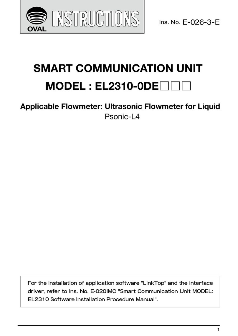
Oval EL 2310-0BE Series User manual

Ins. No. E-025-2-E
MAG-OVAL Ⅲ
SMART COMMUNICATION UNIT
MODEL EL 2310-0BE□□□
Applicable Flowmeter: OVAL Electromagnetic Flowmeters
For the installation of application software "LinkTop" and the interface
driver, refer to Ins. No. E-020IMC "Smart Communication Unit MODEL:
EL2310 Software Installation Procedure Manual".

E-025-2-E
22
CONTENTS
1. SMART COMMUNICATION UNIT......................................................................................... 5
1.1 General .................................................................................................................................... 5
2. BEFORE YOU BEGIN ............................................................................................................. 5
2.1 Inspection upon Receipt .......................................................................................................... 5
2.2 Hookup with Associated Equipment and Devices ................................................................... 6
2.3 Communication Interface......................................................................................................... 7
3. LinkTop OPERATION.............................................................................................................. 8
3.1 LinkTop Screen ........................................................................................................................8
3.2 Starting LinkTop and Connecions............................................................................................ 9
3.3 Terminating the Connection................................................................................................... 11
3.4 Terminating LinkTop............................................................................................................... 12
3.5 Menu: Process Variables (Processing values display)........................................................... 13
3.5.1 Processing Value Measurements (View field device variables) .................................... 13
3.5.2 Chart Display and Logging (Chart and Recording)....................................................... 14
3.5.3 Write Protect (Write protect).......................................................................................... 17
3.6 Menu: Setup (Settings) .......................................................................................................... 18
3.6.1 Flow Rate Parameter (Flow parameter) ........................................................................ 19
3.6.1.1 Nominal Diameter (Nominal diameter)..................................................................... 19
3.6.1.2 Measuring Range (Flow range) ............................................................................... 20
3.6.2 Transmitter Variables (Field device variable) ................................................................ 21
3.6.3 Output Settings (Outputs) ............................................................................................. 22
3.6.3.1 Analog Output (Analog output) ...............................................................................22
3.6.3.2 Pulse Output (Pulse output) .................................................................................... 23
3.6.3.3 Status Output (Status output)..................................................................................25
3.6.3.4 Selecting Status Output Objects (Status select) .................................................... 26
3.6.3.5 Output at Error/Alarm (Error output) ....................................................................... 27
3.6.4 High/Low Alarm (H/L alarm) ......................................................................................... 29
3.6.5 Setting Self Diagnosis (Self diag)..................................................................................30
3.6.6 Device Information (Device information) ....................................................................... 31
3.6.7 Other Settings (Other)................................................................................................... 32
3.6.7.1 Display Setting (Display setting) .............................................................................. 32
3.6.7.2 Security (Security) .................................................................................................. 33
3.6.7.3 Polling Address (Polling address) ........................................................................... 34

E-025-2-E
3.7 Menu: Diag/Service (Checking and Adjustment) ...................................................................35
3.7.1 Self-diagnosis (Self diag) ............................................................................................... 36
3.7.1.1 Circuit Voltage Self-diagnosis (Circuit voltage) ........................................................ 36
3.7.1.2 Coil and Exciting Circuit Diagnosis (Exciting coil/circuit) ......................................... 37
3.7.1.3 Diagnosing Measurement Signal (Measurement signal).......................................... 38
3.7.1.4 Measurement Pipe Empty Detection Function (Empty pipe).................................... 39
3.7.2 Loop Test (Loop test)..................................................................................................... 40
3.7.2.1 Analog Output Loop Test (Fix Analog)..................................................................... 40
3.7.2.2 Pulse Output Loop Test (Fix Pulse) ........................................................................ 41
3.7.2.3 Status Output Loop Test (Fix Status output) ........................................................... 42
3.7.3 Analog Output Adjustment (Trim Analog) ......................................................................43
3.7.4 Cumulative Total Display and Control (Totalizer Control) .............................................46
3.7.5 Setting Accumulated Total Flow (Total flow set) ............................................................46
3.8 Menu: Maintenance (Maintenance) ....................................................................................... 47
3.8.1 Maintaining Transmitter (Maintenance xmtr) ................................................................ 48
3.8.1.1 Error Log Display (Error log) ...................................................................................48
3.8.1.2 Transmitter Internal Temperature Display (Xmtr temp) ............................................50
3.8.1.3 Displaying Operating Time (Operating time) ..........................................................50
3.8.2 Maintenance Test (Maintenance test) ..........................................................................50
3.8.3 Resetting Master (Master reset) .................................................................................. 51
3.9 Menu: Window (Window) ...................................................................................................... 53
3.10 Menu: File (File) ................................................................................................................... 55
3.10.1 Database ..................................................................................................................... 55
3.10.1.1 Opening Files ......................................................................................................... 55
3.10.1.2 Saving Files ...........................................................................................................56
3.10.1.3 Deleting Files ......................................................................................................... 57
3.10.1.4 Downloading .......................................................................................................... 57
3.10.2 Printing ....................................................................................................................... 59
3.11 Troubleshooting.................................................................................................................... 62
3.11.1 If There is No Response ............................................................................................. 62
3.11.2 If It is Not Possible to Connect to the Flowmeter......................................................... 62
3.11.3 Input Errors.................................................................................................................. 62
3.11.4 Error/Alarm, Status List ...............................................................................................63
3.11.4.1 Error/Alarm ............................................................................................................63
3.11.4.2 Status ................................................................................................................... 65
4. PRODUCT CODE EXPLANATION .....................................................................................66
5. GENERAL SPECIFICATIONS ............................................................................................. 67

E-025-2-E
This manual uses the precaution words "NOTE", "CAUTION", and "WARNING" as explained
below:
NOTE: Notes are separated from the general text to bring the user's attention to
important information.
CAUTION: Caution statements inform the user of hazards or unsafe practices which
could result in minor personal injury or product/property damage.
WARNING: Warning statements inform the user of hazards or unsafe practices which
could result in severe personal injury or death.

E-025-2-E
5
1. SMART COMMUNICATION UNIT
1.1 General
Described in this manual are the operating instructions to use the application software LinkTop of the
Smart Communication Unit which operates in the Microsoft operating system Windows environment.
LinkTop is a communication terminal designed for use in combination with a personal computer
(hereinafter referred to as PC) and any one of the OVAL Electromagnetic flowmeters to set up, alter,
adjust, or read out parameters and variables, through interactive communications, either on-site or from
remote locations. Using a Windows PC at hand, you can monitor multiple windows on its screen.
It is necessary to install the application software LinkTop in your personal computer before connecting
the communication interface (*) between the PC and the flowmeter.
NOTE ※:The customer is requested to prepare the communication interface.
2. BEFORE YOU BEGIN
2.1 Inspection upon Receipt
Be sure you have the following items.
Open the product package and make sure you have all the components required.
NOTE: For the installation of the application software "LinkTop" and the interface driver software (※),
refer to "Installation Procedure Manual".
※:The driver software in the CD-ROM is intended for an application of Bell202
Communication Interface for OVAL Smart Communication Unit EL2310. It is not necessary
to install this software when using RS485 communication.
Fig.1
LinkTop
®
for MAG-OVAL
Instruction Manual 1
(This manual)
Instruction Manual 2
(Software Installation Procedure
Manual)
CD-ROM
(Application Software LinkTop)
1
Ins. No. E-020IMC-1-E
MODEL : EL2310
SMART COMMUNICATION UNIT
SOFTWARE INSTALLATION
PROCEDURE MANUAL
*OT/P&&
MAG-OVAL Ⅲ
SMART COMMUNICATION UNIT
MODEL EL 2310-0BE□□□
Applicable Flowmeter: OVAL Electromagnetic Flowmeters
For the installation of application software "LinkTop" and the interface
driver, refer to Ins. No. E-020IMC "Smart Communication Unit MODEL :
EL2310 Software Installation Procedure Manual".
Communication style and communication interface differ with the communication
specification of the flowmeter. The communication specification for standard flowmeter
product is RS485. The flowmeter with Bell202 communication specification is supported
specifically.
- RS485 communication specification: RS485 communication specification is required.
- Bell202 communication specification: Bell202 communication interface for OVAL Smart
Communication Unit EL2310 is required.

E-025-2-E
2.2 Hookup with Associated Equipment and Devices
Equipment set-up with associated equipment and devices is shown in Fig. 2.
(1) In case of RS485 communication
The flowmeter has no built-in terminating resistor. The customer is required to install a terminating
resistor of 120Ω/0.5W at the terminal of the line.
(2) In case of Bell202 communication
Fig.2.1 In Case of RS-485 communication
ERR.
ALM.
PCwithcommunication
softwareinstalled
RS-485
communication
Interface
MAG-OVALⅢ
OutputSignalTerminal
RS-485 +
+
−
−
The receiving instrument in this gure requires a load resistance 250Ω min. Its upper limit depends on
the specication of the transmitter in use.
If the receiving instrument does not have a built-in RL, an external RL needs to be connected in series.
Tie-point Terminal Block
Fig.2.2 In Case of Bell202 Communication
LINE/+
NEUT/−
+ 4 to 20mADC
−
OVAL Electromagnetic
Flowmeter
Receiving Instrument
(Load RL built-in)
RL
Power
LINE/+
NEUT/−
+
−
Probes
Polarity observation is not required.
Connect the probes across + and – terminals
of analog output.
Connection
Points
PC with communication
software installed
Bell202 communication
Interface
Flowmeter
Transmitter
In Fig. 2, the customer is to supply a PC that meets the following requirements:
◇Operating System: Windows XP, Windows Vista, or Windows 7 to 10
◇RAM: 256MB or larger
◇Hard disk: 10MB or larger
◇Serial ports (COM ports) such as USB port or RS232C that are suitable for
connecting to the communication interface shall be provided.
A USB port is required when using Bell202 communication interface for OVAL Smart
Communication Unit EL2310.
NOTE :

E-025-2-E
Fig.3
2.3 Communication Interface
A signal transmitter is provided for the communication signal conversion between the external serial
port (COM port) of the PC and the flowmeter.
When using RS485 communication, the RS485 communication interface available on the market shall
be used.
When using Bell202 communication, the Bell202 communication interface for OVAL Smart
Communication Unit EL2310 shall be used. The signal transmitter consists of the components shown in
Fig. 3.
USB connector
Body
Cable length from probe
500 approx.
Cable length from connector
1000 approx.
50
Probe
(60)
Unit: mm

E-025-2-E
3. LinkTop OPERATION
3.1 LinkTop Screen
① Fig. 4 shows what the LinkTop window looks like.
The communication status is indicated at the bottom left of the screen as:
◇ During communications : SEND, RECEIVE WAIT
◇ Communications interrupted : IDLE
Fig.4
Menu
PC-to-Flowmeter
Communications
Status
Title Bar
Message Box Field
Fig. 6.1

E-025-2-E
3.2 Starting LinkTop and Connections
① Hook up the owmeter transmitter, communication interface, and "LinkTop" pre-installed PC as
shown in Fig. 2.
② To initiate LinkTop, click "Start" at the bottom left of the PC screen and click "LinkTop for
MAG-OVAL" from "Program".
③ Click "Port setting (I) Ctrl + I" under "File (F)" from the menu.
Fig.5
④ Set up the port.
Select the COM□ of the corresponding communication port from the "Port" drop-down list.
(□ shows the port number connected to the communication interface. If the corresponding
communication interface port number is unknown, open Windows Device Manager and nd the port
number from the list of "Port (COM and LPT)".)
Click here.
Then, select the corresponding specication (baud rate) from the "Speed" list in accordance with
the communication specications of the owmeter.
- In case of RS485 communication: Select RS485.
Choose the baud rate from 9600bps, 19200bps or 38400bps to meet the baud rate set for the
owmeter. The standard baud rate set for the owmeter is 19200bps.
(For the setting method of baud rate (RS485 communication speed) for flowmeter, refer to
"Electromagnetic Flowmeter MAG-OVAL III Instruction Manual".)
- In case of Bell202 communication: Select Bell202 (The baud rate for Bell202 is xed.)
Finally, click "OK" .
Fig. 6.1 Fig. 6.2

E-025-2-E
0
⑤ Click "Connect (C) F3" under "File (F)" from the menu.
Fig.7
Click here.
⑥ The "Polling address" setting screen appears. The standard "Polling address" of the owmeter is "0".
After you select "0", click "OK" to initiate the connection.
If "Polling address" of the owmeter is unknown, conrm "Polling address" by
the operation of the owmeter. ⇨ Reference: Flowmeter Instruction Manual
(Communication Function)
Fig.8
⑦ A message box shown as Fig.9 appears as the connection process begins.
A bar graph in the middle of message box indicates progress of connection process.
Fig.9
⑧ Upon completion of connections, a message box shown as Fig. 10 appears. Click "OK" .
Fig.10
( )

E-025-2-E
⑨ When connection is complete, all functions of the menu become selectable as shown below.
Fig.11
3.3 Terminating the Connection
To terminate connection between the owmeter transmitter and LinkTop, follow the procedure given
below:
① Click on "Disconnect (D) Shift + F3" as shown in Fig. 12.
Fig.12
② At the message box as shown in Fig. 13, click "OK". This terminates the connection between the
owmeter and LinkTop.
Fig.13
Click here.

E-025-2-E
2
③ When connection is terminated, some functions of the menu become inactive as shown in
Fig. 14.
Fig.14
3.4 Terminating LinkTop
To exit LinkTop, click "File (F)" from the menu then select "Exit (E)". A message box as shown in
Fig. 15 appears. Click "OK" to conrm and the application software window will disappear from the
desktop.
To abort the terminating process, click on "Cancel".
Fig.15

E-025-2-E
3.5 Menu: Process Variables (Processing values display)
The "Process Variables" menu can be used to confirm the display of flowmeter's process values
(instantaneous ow rate, total ow, and ow velocity), chart display, logging, and Write Protect mode.
Fig.16
3.5.1 Processing Value Measurements (View eld device variables)
① Click "Process Variables (V)" from the menu, then select "View eld device variables" .
② The following window will be displayed (Fig. 17).
Fig.17
「Percent ow rate」…Percent ow rate (Instantaneous ow rate)
「Flow rate」…Actual ow rate (Instantaneous ow rate)
「Total count」…Accumulated total ow counter
「Total ow」…Accumulated total ow

E-025-2-E
「Total overow count」…The number of times counted when accumulated total ow value
returns to "zero" by exceeding the maximum reading.
「R-Total count」…Resettable ow totalizing counter
「R-Total ow」…Resettable total ow
「R-Total overow count」…The number of times counted when resettable total ow returns
to "zero" by exceeding the maximum reading.
3.5.2 Chart Display and Logging (Chart and Recording)
Chart display of ow rate and ow velocity as well as data logging can be carried out.
① Click "Chart and Recording" from the menu, and select "Active" , then a tool bar as shown in
Fig. 18 will appear underneath the menu.
③ If there is a problem with the owmeter transmitter, then an error message will be displayed in the
window under the process value measurement window. For details, refer to section 3.11.4 "Error/
Alarm, Status List".
④ To exit, click "Cancel".
② Click the button on the tool bar or "Chart and Recording" - "Interval" of the menu, then the
window as shown in Fig. 19 appears, enabling setting of update interval of chart display and
logging interval.
Select the preferred interval from "0.2 Second" (only in RS485 communication), "0.5 Second" (only
in RS485 communication), "1 Second", "3 Seconds", "5 Seconds", "10 Seconds", "30 Seconds",
"1 Minute", "5 Minutes", "10 Minutes", and "1 Hour" and click "OK".
Fig.18
Fig.19

E-025-2-E
5
④ A chart is drawn at the intervals of update set in ②.
Fig.20
⑤ To hide the chart, click the button of the tool bar or "Chart and Recording" - "Chart" - "Percent
ow rate" from the "Proccess Variables (V)" menu.
Fig.21
③ Click the button of the tool bar or "Chart and Recording" - "Chart" - "Percent ow rate" from
the menu, then the window as shown in Fig. 20 is displayed, enabling chart display of Percent
ow rate.
When changing the scale of the vertical axis, enter the preferred values to "Max" and "Min", then
click "OK".

E-025-2-E
⑥ Similarly, by clicking the button of the tool bar or "Chart and Recording" - "Chart" - "Flow rate"
from the "Proccess Variables (V)" menu, actual ow rate can be shown or hidden. If you click the
button or "Chart and Recording" - "Chart" - "Flow velocity" from the "Proccess Variables (V)"
menu, ow velocity chart can be shown or hidden as well.
⑦ If you click the button of the tool bar or "Chart and Recording" - "Recording" - "Start" in the
menu, the following dialog box (Fig. 22) is displayed. Select the disk and folder to create a le,
enter a le name, and click "Save (S)". A CSV le is created and data logging begins.
Fig.22
⑧ If you click the button of the tool bar or "Chart and Recording" - "Recording" - "Stop" in the
menu, logging stops (terminating the writing process on the le) and the le is completed. Then the
following message box (Fig. 23) is displayed. Click "OK".
Fig.23

E-025-2-E
Fig.24
⑩ If you click the button of the tool bar or "Chart and Recording" - "Active" from the menu, chart
display and data logging are terminated.
3.5.3 Write Protect (Write protect)
① Click "Process Variables (V)" on the menu and select "Write protect", then the following window
(Fig. 25) will be displayed.
② To exit this procedure, click "Cancel".
Date and time Percent ow rate Flow rate Flow velocity
Fig.25
"Write protect" shows whether parameter change of the transmitter is available or not.
Mode Detail SW1-4 Setting
Not write protected Enables changing and setting parameters. OFF
Write protected Disables changing and setting parameters.
(Conrmation of parameters is available.) ON
NOTE : Selecting the above mode is available by changing switches SW1-4 on the
CPU board of the flowmeter transmitter.
⑨ The content of the log le when logging interval is set to "5 Seconds" is as shown in Fig. 24.

E-025-2-E
3.6 Menu : Setup (Settings)
The "Setup" menu can be used to set owmeter's various parameter values, transmitter's information,
and so on.
If any windows of "Diag/Service" menu is displayed on the screen, then it will not be possible to
set the various parameters, transmitter information, and so on. Close these windows before making
settings. For the actual screen, refer to Fig. 26.
Fig.26
Setup Flow parameter Nominal diameter
Flow range
Field device variable
Outputs
Analog output
Pulse output
Status output
Status select
Error output
H/L alarm
Self diag
Device information
Other
Display setting
Security
Polling address
Setup Item Tree

E-025-2-E
3.6.1 Flow Rate Parameter (Flow parameter)
3.6.1.1 Nominal Diameter (Nominal diameter)
① Click "Setup (S)" from the menu, and select "Nominal diameter" from the drop-down list of "Flow
parameter", then the following window (Fig. 27) will be displayed.
Fig.27
② Select the correct nominal diameter.
③ Click "OK" after the setting is completed to display the message box (Fig. 28). Click "OK" here
to change the settings to the inputted values, and to reect the changed setting values in the
owmeter's output. If the owmeter's output is used to control valves or other such parts as safety
protocol, change that control loop to manual control so that the control loop cannot be inuenced
by the owmeter's output.
④ The message box (Fig. 29) is displayed after changing the setting values. Click "OK" to complete
the setting process.
⑤ The window for setting item is displayed. To exit, click "Cancel".
Setting item Detail Setting range
Nominal diameter Nominal diameter of sensor
(Select from the right column.)
3mm, 4mm, 6mm, 8mm, 10mm, 15mm,
20mm, 25mm, 32mm, 40mm, 50mm,
65mm, 80mm, 100mm, 125mm, 150mm,
200mm
Fig.28
Fig.29

E-025-2-E
20
3.6.1.2 Measuring Range (Flow range)
① Click "Setup (S)" from the menu then select "Flow range" from the drop-down list of "Flow
parameter", then the following window (Fig. 30) will be displayed.
Fig.30
② Enter a numeric value for the item.
③ Click "OK" after the setting is completed to display the message box (Fig. 31). Click "OK" here
to change the settings to the inputted values, and to reect the changed setting values in the
owmeter's output. If the owmeter's output is used to control valves or other such parts as safety
protocol, change the control loop to manual control so that the control loop cannot be inuenced
by the owmeter's output.
Fig.31
④ The message box (Fig. 32) is displayed after changing the setting values. Click "OK" to complete
the setting process.
Fig.32
⑤ The window for setting item is displayed. To exit, click "Cancel".
Setting item Detail Setting range
Flow range Measuring range (Full scale flow) Minimum range to Maximum range
Table of contents
Other Oval Conference System manuals
Popular Conference System manuals by other brands

AT&T
AT&T MERLIN Attendant for MERLIN LEGEND Installer's guide

Fisher & Paykel
Fisher & Paykel CG451 installation instructions

Extron electronics
Extron electronics Cable Cubby 1200 installation guide

Vodavi
Vodavi Starplus STSe quick start guide

Altwork
Altwork TruVue Assembly and Use

Shure
Shure MXA902 manual