MSA GALLET MICRO GA1032 Series User manual

Ref. : 180249 - PR210044/3
Imp. Mult tude 01 Chât llon/Chalaronne
MSA GALLET
B.P. 90
Z.I. sud
F-01400 Châtillon-sur-Chalaronne
Tél.+33 (4 74 55 01 55
Fax.+33 (4 74 55 24 80
Email : [email protected]
www.msa-gallet.fr
MICRO
REF : GA1032xxxx
REF : GA1032xxxx
FGB D NL E
[
Systèmes de communication
][
Communication systems
]
[
Hör-S rech Garnitur
][
Communicatie-uistrusting
]
[
Systema de comunicación
]

SOMMAIRE
Page
AVERTISSEMENT.................................................................................. 2
MONTAGE / DEMONTAGE
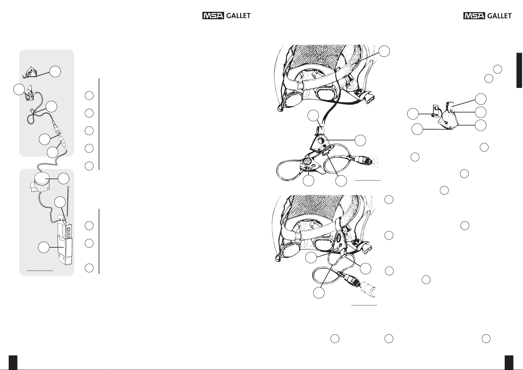
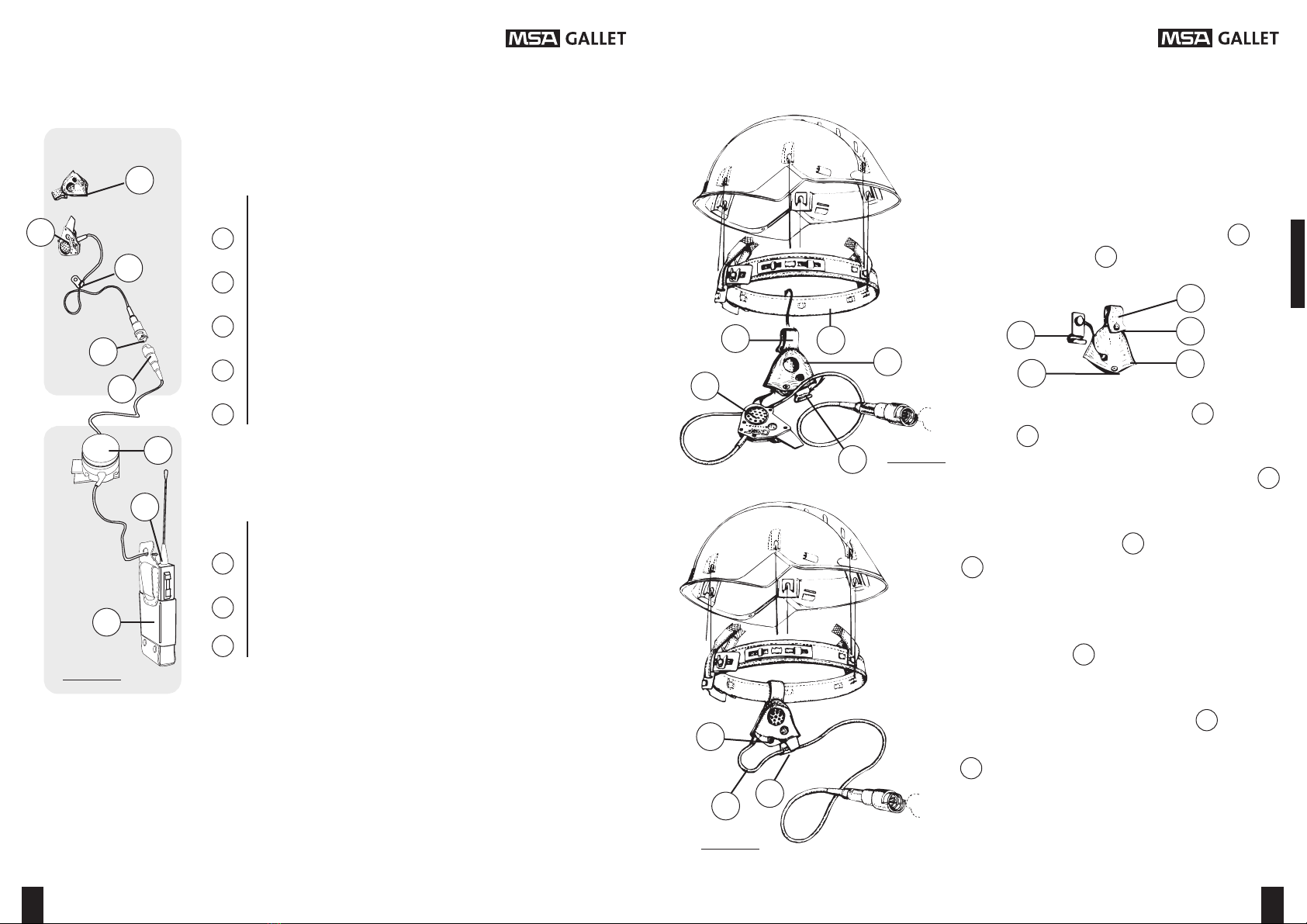
1-Compos t on de l’équ pement pour un casque F1....................... 4
2-1 Installat on de l’équ pement de tête dans un casque F1.......... 5
2-2 Démontage ............................................................................... 5
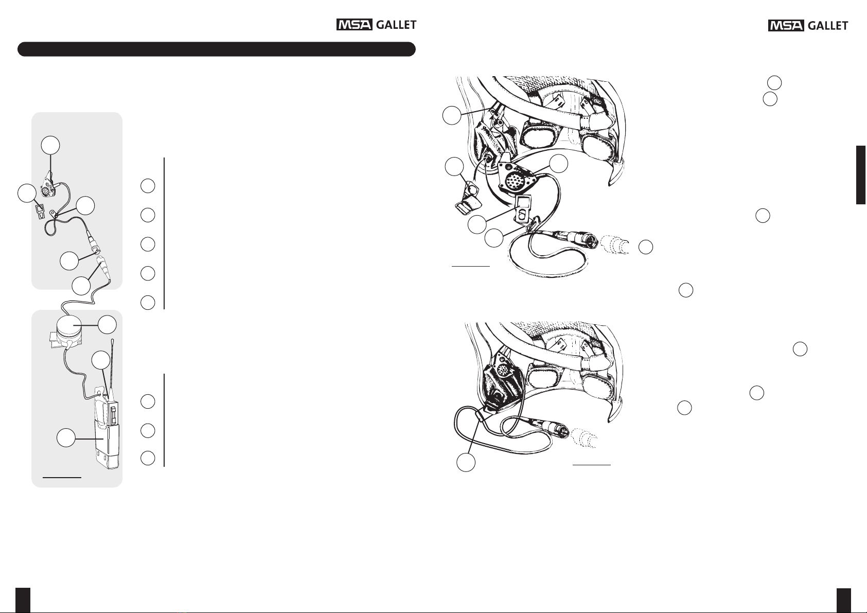
3- Compos t on de l’équ pement pour un casque F2...................... 6
4-1 Installat on de l’équ pement de tête dans un casque F2 ......... 7
4-2 Démontage ............................................................................... 7
5- Compos t on de l’équ pement pour un bandeau......................... 8
6-1 Installat on de l’équ pement de tête sur un bandeau .............. 9
6-2 Démontage ............................................................................... 9
7- Compos t on de l’équ pement pour un casque F1A ................... 10
8-1 Installat on de l’équ pement de tête dans un casque F1A ....... 11
8-2 Démontage ............................................................................... 11
9- Installat on de l’équ pement de transm ss on ............................. 12
USAGE
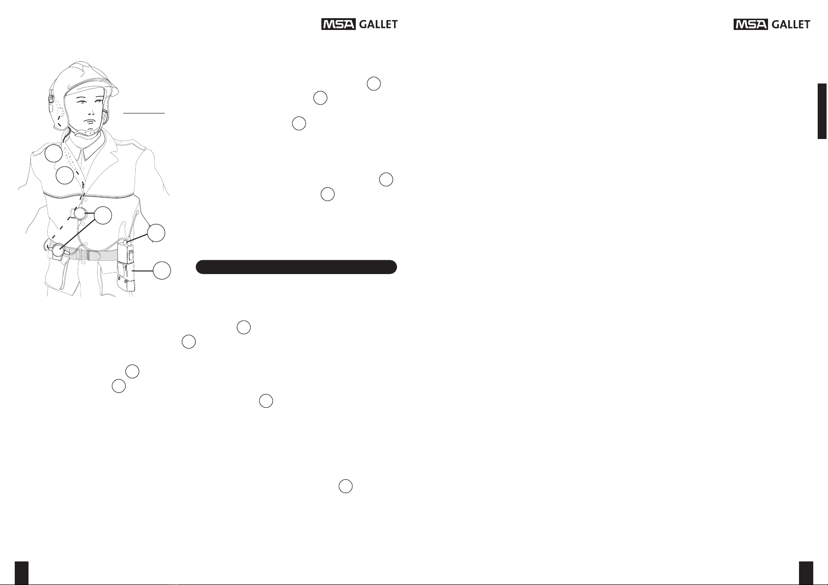
10- Ut l sat on .................................................................................. 12
11- Boît er P.T.T. (Push To Talk : appuyer pour parler) avec p les.. 12
12- Caractér st ques techn ques ..................................................... 13
13- Cond t ons d’ut l sat on et de stockage
13.1- Stockage................................................................................ 13
13.2- Ut l sat on .............................................................................. 13
13.3- Nettoyage éventuel................................................................ 13
14- Garant e et responsab l té ........................................................ 14
AVERTISSEMENT : Nous vous remerc ons pour la conf ance que vous témo gnez aux produ ts MSA GALLET.
Cette Notice d’Utilisation doit être lue attentivement.
Toute mod f cat on apportée à l’appare l ou la suppress on de l’une des p èces le const tuant entraînera une
non conform té du matér el l vré, dégageant de toute responsab l té la Soc été MSA GALLET.
Dans le cas de l’ut l sat on de systèmes de commun cat on MSA GALLET, homologués EEX, vous devez
mpérat vement les connecter sur des émetteurs-récepteurs correspondants homologués EEX.
Des équ pements non EEX ne do vent pas être assoc és à des émetteurs-récepteurs EEX.
Toujours soucieuse d’améliorer ses produits, la société MSA GALLET se réserve le droit de les
modifier sans préavis.
WARNING : We thank you for your trust n MSA GALLET products.
The instructions for use should be read carefully.
Any mod f cat on made on the product as well as the lock of one of the components w ll lead to the non
conform ty of the suppl ed mater al and w ll release MSA GALLET from all l ab l ty.
When us ng MSA GALLET EEX cert f ed commun cat on systems, you should connect them on EEX cert f ed
rad os.
Equ pment wh ch are not EEX should not be used w th EEX cert f ed rad os.
In order to improve products at anytime, MSA GALLET retains t e rig t to alter and modify t e
specifications wit out previous notice.
WARNUNG : W r bedanken uns für Ihr Vertrauen an d e MSA GALLET Produkte.
Die vorliegende Bedienungsanweisung ist sorgfältig durchzulesen.
Jede auf dem Gerät vorgenommene Abänderung oder d e Entnahme e nes Bestandte les w rd zu e ner N cht-
Konform tät des gel eferten Mater als führen, wobe d e F rma MSA GALLET von jeder Haftung befre t st.
Be Benuztung der EEX homolog erten Kommun kat onsanlagen MSA GALLET, s nd s e erzw ngend m t
enstprechenden EEX homolog erten Sendern-Empfängern zu verb nden.
N cht EEX homolog erte E nr chtungen dürfen auf ke nen Fall an EEX Sender-Empfänger angeschlossen werden.
Mit dem Ziel, i re Produkte fortlaufend zu verbessern, vorbe altet sic die Firma
MSA GALLET das Rec t, sie jederzeit o ne vor erige Mitteilung abzuändern.
WAARSCHUWING : W j danken u voor uw vertrouwen n de produkten van MSA GALLET.
Deze gebruiksaanwijzing moet aandachtig worden doorgelezen.
Het w jz gen of verw jderen van onderdelen van het apparaat kan tot gevolg hebben dat het geleverde
mater aal n et langer meer conform s en dat de f rma MSA GALLET n et meer aansprakel jk kan worden gesteld.
In geval van gebru k van commun cat esystemen van MSA GALLET met EEX-goedkeur ng, d ent u deze
verpl cht aan te slu ten op zender-ontvangers conform de EEX-goedkeur ng.
Apparatuur zonder EEX-goedkeur ng mag n et worden aangesloten op EEX zender-ontvangers.
In et kader van aar voortdurende inspanningen aar produkten te verbeteren, be oudt MSA
GALLET zic et rec t voor om aar produkten zonder voorafgaande kennisgeving te wijzigen.
ADVERTENCIA : Le agradecemos la conf anza que presta a los productos MSA GALLET.
Lea detenidamente las resentes Instrucciones de utilización.
Cualqu er mod f cac ón efectuada en el aparato o la supres ón de una de las p ezas que lo const tuyen
conllevará la no conform dad del mater al sum n strado y el m nará la responsab l dad de la Soc edad MSA GALLET.
S ut l za s stemas de comun cac ón MSA GALLET, homologados EEX, deberá conectarlos a em sores-
receptores correspond entes homologados EEX.
No asoc e nunca equ pos que no sean EEX a em sores-receptores EEX.
La Sociedad MSA GALLET, pendiente siempre de mejorar sus productos, se reserva el derec o de
modificarlos sin previo aviso.
2
FRANÇAIS 3 à 14
ENGLISH 15 to 26
DEUTSCH 27 bis 38
NEDERLANDS 39 tot 50
ESPAÑOL 51 a 62
3

F xez l’ensemble m cro-écouteur (f gure 2)
dans la ra nure prévue à cet effet. Elle est
s tuée sur le côté ntér eur dro t du casque
(elle sert auss pour f xer la co ffe).
Dans le cas de l’ut l sat on d’un bavolet, prat quez
dans celu -c une nc s on hor zontale de 2 cm en
face de la ra nure .
Pour placer la f xat on ant -arrache câble ,
décl psez le côté dro t de la jugula re à l’a de
d’un tournev s plat.
Pos t onnez la part e év dée de la f xat on ant -
arrache câble sur la press on mâle, pu s
recl psez la jugula re.
Faîtes gl sser avec précaut on le câble à
l’ ntér eur de la goutt ère du support ant -
arrache câble en la ssant un peu de
réserve de câble pour le débattement.
Encl quetez le support ant -arrache câble
sur la f xat on ant arrache câble .
2-1 Installation de l’équi ement de tête dans un casque F1 :
1- Com osition de l’équi ement our un casque F1 :
MONTAGE / DEMONTAGE
EQUIPEMENT DE TETE
EQUIPEMENT DE TRANSMISSION
BOITIER P.T.T. AVEC PINCE
FICHE DE RACCORDEMENT SPÉCIFIQUE À CHAQUE
TYPE DE POSTE ÉMETTEUR RÉCEPTEUR
POSTE EMETTEUR-RECEPTEUR (NON FOURNI)
SUPPORT ANTI-ARRACHE CABLE
FICHE AUTO-CASSANTE
ENSEMBLE MICRO-ECOUTEUR
FIXATION ANTI-ARRACHE CABLE
DETROMPEUR DE COULEUR JAUNE
Désignation
Désignation
FIGURE 1
FIGURE 2
FIGURE 3
Référence : GA1032x1xx
(Su te page 12)
2-2 Démontage :
Su vez l’ordre nverse du montage, décl quetez le support ant -arrache câble de la
f xat on . La ssez sur le casque la f xat on ant -arrache câble .
4
1
5
23
4
5
6
7
8
1
9
1
3
2
10
3
9
9
2
10
2
3
3
2
3
2 2
1
2
3
4
5
6
7
8

Introdu sez dans le trou de la pochette , le
téton du support ant -arrache câble .
3- Com osition de l’équi ement our un casque F2 :
EQUIPEMENT DE TETE
EQUIPEMENT DE TRANSMISSION
BOITIER P.T.T. AVEC PINCE
FICHE DE RACCORDEMENT SPÉCIFIQUE À CHAQUE
TYPE DE POSTE ÉMETTEUR RÉCEPTEUR
POSTE EMETTEUR-RECEPTEUR (NON FOURNI)
SUPPORT ANTI-ARRACHE CABLE
FICHE AUTO-CASSANTE
ENSEMBLE MICRO-ECOUTEUR
POCHETTE ENSEMBLE MICRO-ECOUTEUR
DETROMPEUR DE COULEUR JAUNE
Désignation
Désignation
FIGURE 4
Mettez l’ensemble m cro-écouteur dans la
pochette .
Fermez le bouton-press on (f gure 6).
Passez la languette par dessus le bandeau
, vers le m l eu gauche du casque, l’écouteur
do t être tourné vers la tête du porteur.
Fermez le bouton-press on de la languette .
Gl ssez avec précaut on le câble à l’ ntér eur
de la goutt ère du support ant -arrache câble
en la ssant un peu de câble l bre pour le
débattement .
Pour plus de clarté, les figures 5 et 6
représentent la coiffe séparée du casque.
Cependant, celle-ci ne doit pas être démontée
pour l’installation.
4-1 Installation de l’équi ement de tête dans un casque F2 :
FIGURE 5
FIGURE 6
Référence : GA1032x2xx
4-2 Démontage :
Ret rez la languette de la pochette en
ouvrant le bouton-press on .
(Su te page 12)
67
1
11
3
4
5
6
7
8
11
1
3
4
5
6
7
8
13 14 11
3
1
12
16 3
3
12 11
15
13
11
3
1
11
12
13
14
15
3
16
13 11
12

5- Com osition de l’équi ement our un bandeau :
EQUIPEMENT DE TETE
EQUIPEMENT DE TRANSMISSION
BOITIER P.T.T. AVEC PINCE
FICHE DE RACCORDEMENT SPÉCIFIQUE À CHAQUE
TYPE DE POSTE ÉMETTEUR RÉCEPTEUR
SUPPORT ANTI-ARRACHE CABLE
FICHE AUTO-CASSANTE
ENSEMBLE MICRO-ECOUTEUR
POCHETTE ENSEMBLE MICRO-ECOUTEUR
BANDEAU
DETROMPEUR DE COULEUR JAUNE
Désignation
Désignation
FIGURE 7
6-1 Installation de l’équi ement de tête sur un bandeau :
FIGURE 8
FIGURE 9
Mettez l’ensemble m cro-écouteur dans la
pochette .
Fermez le bouton-press on (f gure 9).
Passez la languette par dessus le bandeau
, vers le m l eu gauche du casque, l’écouteur
do t être tourné vers la tête du porteur.
Fermez le bouton-press on de la languette .
Gl ssez avec précaut on le câble à l’ ntér eur
de la goutt ère du support ant -arrache câble
en la ssant un peu de câble l bre pour le
débattement .
Mettez le bandeau sur la tête avec l’ensemble
m cro-écouteur à votre gauche.
Référence : GA1032x3xx
Introdu sez dans le trou de la pochette , le
téton du support ant -arrache câble .
(Su te page 12)
6-2 Démontage :
Ret rez le bandeau avec l’ensemble m cro-écouteur.
89
POSTE EMETTEUR-RECEPTEUR (NON FOURNI)
11
17
1
3
4
5
6
7
8
17
11
1
3
4
5
6
7
8
17
13 11
1
3
12
16 3
3
12 11
15
13
11
3
1
11
12
13
17
15
3
16

8-1 Installation de l’équi ement de tête dans un casque F1A :7- Com osition de l’équi ement our un casque F1A :
FIGURE 10
FIGURE 11
FIGURE 12
Mettez l’ensemble m cro-écouteur dans la
pochette .
Fermez le bouton-press on (f gure 12).
Passez la languette par dessus le bandeau
, vers le m l eu gauche du casque, l’écouteur
do t être tourné vers la tête du porteur.
Fermez le bouton-press on de la languette
.
Gl ssez avec précaut on le câble à l’ ntér eur
de la goutt ère du support ant -arrache câble
en la ssant un peu de câble l bre pour le
débattement .
Référence : GA1032x2xx
Introdu sez dans le trou de la pochette , le
téton du support ant -arrache câble .
8-2 Démontage :
Ret rez la languette de la pochette en ouvrant le bouton-press on .
10 11
EQUIPEMENT DE TETE
EQUIPEMENT DE TRANSMISSION
BOITIER P.T.T. AVEC PINCE
FICHE DE RACCORDEMENT SPÉCIFIQUE À CHAQUE
TYPE DE POSTE ÉMETTEUR RÉCEPTEUR
POSTE EMETTEUR-RECEPTEUR (NON FOURNI)
SUPPORT ANTI-ARRACHE CABLE
FICHE AUTO-CASSANTE
ENSEMBLE MICRO-ECOUTEUR
POCHETTE ENSEMBLE MICRO-ECOUTEUR
DETROMPEUR DE COULEUR JAUNE
Désignation
Désignation
1
11
3
4
5
6
7
8
11
1
3
4
5
6
7
8
14
13
11
3
1
12
3
16
11
3
1
11
12
13
14
15
13
3
16
3
12 11
15
13
13 11 12

12- Caractéristiques techniques :
- M crophone : M cro-électret, Bande Passante de 50 Hz à 12 kHz.
Sens b l té : 5 mV / Pa / 1 kHz , ± 2 dB.
- Ampl f cateur : Ga n réglable de 0 à 26 dB.
Bande Passante de 300 Hz à 3kHz à -3dB.
Sort e nom nale 50 mV RMS sous 1 kΩ/ ou adaptable.
D stors on harmon que : 5 %.
- Haut-parleur : 1 x 32 Ω.
Bande Passante 20 Hz à 3 kHz.
Pu ssance max male : 100 mW.
- Al mentat on : 6 V à 18 V.
Consommat on 600 µA sous 7 V (bouton P.T.T. appuyé).
0 µA (bouton P.T.T. relaché).
- Masse de l’équ pement de tête : (55 ± 2) g.
- Ret rez la mousse de protect on du bo t er P.T.T. .
- Mettez le poste émetteur-récepteur en fonct onnement (su vre les nstruct ons du
constructeur).
- Appuyez sur le bouton et parlez pour transmettre un message.
- Relachez le bouton pour être en mode récept on. Le n veau sonore reçu se règle
à l’a de du bouton de volume de l’émetteur-récepteur .
- Il n’est pas conse llé de mettre le poste émetteur-récepteur à prox m té du boît er P.T.T.
(r sque de rayonnements ndés rables).
11- Boitier P.T.T. avec iles :
Dans le cas des postes émetteurs et récepteurs ne d sposant pas d’une broche
d’al mentat on sur la pr se accesso re (exemple pr se jack), le boît er P.T.T. comporte
deux p les l th um de 3 volts.
Ces p les ne sont soll c tées que pendant l’ém ss on, la
consommat on des c rcu ts électron ques est suff samment fa ble pour qu’elles pu ssent
durer plus eurs années. Néanmo ns, l est prudent de vér f er régul èrement leur bon
fonct onnement et de les fa re changer au mo ns tous les c nq ans.
9- Installation de l’équi ement de transmission :
Connectez la f che de raccordement au
poste émetteur-récepteur . (poste éte nt)
F xez le boît er P.T.T. à l’a de de sa p nce
au revers de la veste ou à la ce nture,
mâcho res de la p nce vers le haut.
Raccordez les deux f ches auto-cassantes ,
en mettant les détrompeurs en regard.
10- Utilisation :
FIGURE 13
USAGE
13- Conditions d’utilisation et de stockage :
13.1- Stockage : -40 °C à + 80 °C, hum d té relat ve 0 à 98%.
13.2- Utilisation : -20 °C à + 65 °C, hum d té relat ve 0 à 98%.
13.3- Nettoyage éventuel : avec une éponge mb bée d’eau savonneuse.
Ne pas employer de solvants ou d’hydrocarbures.
Ne pas mmerger.
12 13
4
5
6
7
8
7
8
6
4
5
6
8
6
6
8
6

- Garant e légale :
Le cl ent f nal bénéf c e de la garant e légale pour défauts et v ces cachés dans les
cond t ons prévues aux art cles 1641 et su vants du Code C v l.
- Garant e contractuelle :
La soc été MSA GALLET garant t l’appare l douze mo s à compter de sa date de
vente, la date appara ssant sur la facture servant de preuve. L’appare l vendu au cl ent
f nal est cons déré comme étant de qual té marchande, l bre de tout v ce de fabr cat on
ou de tout défaut.
Toutefo s, l est entendu que l’appare l devra fa re l’objet d’un usage normal et
conforme à la présente not ce d’ut l sat on.
Le cl ent f nal do t not f er par écr t à la soc été MSA GALLET tout défaut du produ t
dans les c nq jours ouvrés su vant sa survenance.
La garant e de l’appare l est l m tée au remplacement gratu t ou à la fourn ture de la
p èce ou des p èces reconnues défectueuses. La soc été MSA GALLET optera pour
l’une ou l’autre des solut ons. La garant e de la soc été MSA GALLET ne comprend pas
les fra s d’ ntervent on sur l’appare l.
La soc été MSA GALLET att re l’attent on du D str buteur et du cl ent f nal sur le fa t
qu’elle décl ne toute responsab l té dans les cas su vants :
- usure normale, mpact, mauva se ut l sat on, détér orat on ou acc dents provenant
de négl gences (défaut de surve llance, d’entret en ou d’ut l sat on) ou encore une
transformat on quelconque de l’appare l.
- ouverture du boît er ‘Push To Talk’ par l’ut l sateur.
- réparat on, altérat on ou ut l sat on qu est hors des spéc f cat ons posées par la
soc été MSA GALLET.
- dommages causés à des personnes ou à des b ens du fa t de l’emplo de
l’appare l.
En tout état de cause, la responsab l té de la soc été MSA GALLET est exclue pour
tous dommages nd rects et /ou mmatér els, tout fra s, pertes, coûts (même s la soc été
MSA GALLET a conna ssance de leur ex stence) causés par le produ t.
14- Garantie et res onsabilité :
CONTENTS
Page
WARNING............................................................................................... 2
ASSEMBLY / DISASSEMBLING
1- Components for the F1 helmet .................................................. 16
2-1 Installat on head equ pment n the F1 helmet .......................... 17
2-2 D sassembl ng .......................................................................... 17
3- Components for the F2 helmet................................................... 18
4-1 Installat on head equ pment n the F2 helmet .......................... 19
4-2 D sassembl ng .......................................................................... 19
5- Component parts headband ...................................................... 20
6-1 Installat on head equ pment headband ................................... 21
6-2 D sassembl ng .......................................................................... 21
7- Components for the F1A helmet ................................................ 22
8-1 Installat on head equ pment n the F1A helmet........................ 23
8-2 D sassembl ng .......................................................................... 23
9- Installat on transm ss on equ pment ........................................... 24
USE INSTRUCTIONS
10- Instruct ons for use ................................................................... 24
11- P.T.T. set (Push To Talk) w th batter es ..................................... 24
12- Techn cal features..................................................................... 25
13- Use and storage cond t ons
13.1- Storage .................................................................................. 25
13.2- Use ........................................................................................ 25
13.3- Clean ng ............................................................................... 25
14- Warrant es and L ab l t es ......................................................... 26
14 15

16 17
1- Com onents for an F1 Helmet:
ASSEMBLY / DISASSEMBLING
HEAD EQUIPMENT
TRANSMISSION EQUIPMENT
PTT (PUSH TO TALK) SET WITH CLIP
CONNECTOR PLUG DEPENDING ON THE RADIO TYPE
TRANSMITTER/RECEIVER SET (NOT SUPPLIED)
ANTI-TEAROUT DEVICE
SELF-BREAKING PLUG
MICRO-EARPHONE SET
BRACKET FOR ANTI-TEAROUT DEVICE
YELLOW LOCATING LUG
S ecifications
S ecifications
FIGURE 1
Reference : GA1032x1xx
1
23
4
5
6
7
8
1
2
3
4
5
6
7
8
F x the m cro-earphone set (fgure 2) nto
the spec ally des gned slot .Th s s located
on the r ght ns de of the helmet ( t also serves
to secure the head band).
In case that a necksk rt s used t s necessary to
make a hor zontal cut of around 2 cm oppos te to
the groove.
To anchor the bracket for ant -tearout
dev ce, unfasten the r ght s de of the ch nstrap
us ng a flat screw-dr ver.
Pos t on the hollow sect on of the ant -tearout
bracket over the male s de of the press-
cl p, then place the ch nstrap nto pos t on.
Carefully sl de the cable nto the hold ng
groove of the ant -tearout dev ce , leav ng
a small length of cable to allow movement.
Cl ck the ant -tearout dev ce onto the
bracket .
2-1 Installation head equi ment into an F1 helmet:
FIGURE 2
FIGURE 3
(See page 24)
2-2 Disassembling:
Follow the nstruct ons for assembly n the oppos te way, d sconnect the support to avo d
the cable from pull ng out. Leave the th s part n the helmet.
1
9
1
3
2
10
3
9
2
10
3
3
2
2

18 19
3- Com onent for an F2 helmet:
HEAD EQUIPMENT
TRANSMISSION EQUIPMENT
PTT SET WITH CLIP
CONNECTOR PLUG DEPENDING ON THE RADIO TYPE
TRANSMITTER/RECEIVER SET (NOT SUPPLIED)
ANTI-TEAROUT DEVICE
SELF-BREAKING PLUG
MICRO-EARPHONE SET
MICRO-EARPHONE POCKET
YELLOW LOCATING LUG
S ecifications
S ecifications
FIGURE 4
Reference : GA1032x2xx
1
11
3
4
5
6
7
8
11
1
3
4
5
6
7
8
Press the n pple of ant -tearout dev ce nto
the hole of pocket .
Place the m cro-earphone set nto the
pocket .
Close the pocket us ng the press-stud
(f gure 6).
Place the hold ng loop onto the headband
at a m ddle left pos t on n the helmet. The
earphone must be turned towards the wearer's
head.
Close the loop us ng the press-stud.
Carefully sl de the cable ns de the hold ng
groove of the ant -tearout dev ce , leav ng
a small length of cable to allow movement
.
Please note that for the sake of clarity, figures
5 and 6 sho the headband is sho n separate
from the helmet. Ho ever it should not be
removed from the helmet hen installing the
head equipment.
4-1 Installation head equi ment into F2 helmet:
FIGURE 5
FIGURE 6
4-2 Disassembling:
Pull the small l p out of the pocket wh le pull ng
the press-button.
(See page 24)
13 14 11
3
1
12
16 3
3
12 11
15
13
11
3
1
11
12
13
14
15
3
16

20 21
5- Com onents headband:
HEAD EQUIPMENT
TRANSMISSION EQUIPMENT
PTT SET WITH CLIP
CONNECTOR PLUG DEPENDING ON THE RADIO TYPE
ANTI-TEAROUT DEVICE
SELF-BREAKING PLUG
MICRO-EARPHONE SET
MICRO-EARPHONE POCKET
HEADBAND
YELLOW LOCATING LUG
S ecifications
S ecifications
FIGURE 7
Reference : GA1032x3xx
TRANSMITTER/RECEIVER SET (NOT SUPPLIED)
11
17
1
3
4
5
6
7
8
17
11
1
3
4
5
6
7
8
6-1 Installation head equi ment onto headband:
FIGURE 8
FIGURE 9
Place the m cro-earphone set nto pocket
.
Close the pocket us ng the press-stud
(f gure 9).
Place the hold ng loop on the headband
at a m ddle left pos t on n the helmet. The
earphone must be turned towards the wearer's
head.
Close the loop us ng the press-stud.
Carefully sl de the cable ns de the hold ng
groove of the ant -tearout dev ce , leav ng
a small length of cable to allow movement
.
Place the headband on the head w th the
m cro-earphone on the left.
Press the n pple of ant -tearout dev ce nto
the hole of pocket .
(See page 24)
6-2 Disassembling:
Take the headband out together w th the m cro-speaker part.
17
13 11
1
3
12
16 3
3
12 11
15
13
11
3
1
11
12
13
17
15
3
16

22 23
7- Com onents F1A helmet:
FIGURE 10
Reference : GA1032x2xx
HEAD EQUIPMENT
TRANSMISSION EQUIPMENT
PTT SET WITH CLIP
CONNECTOR PLUG DEPENDING ON THE RADIO TYPE
TRANSMITTER/RECEIVER SET (NOT SUPPLIED)
ANTI-TEAROUT DEVICE
SELF-BREAKING PLUG
MICRO-EARPHONE SET
MICRO-EARPHONE POCKET
YELLOW LOCATING LUG
S ecifications
S ecifications
1
11
3
4
5
6
7
8
11
1
3
4
5
6
7
8
8-1 Installation head equi ment into F1A helmet
:
FIGURE 11
FIGURE 12
Place the m cro-earphone set nto pocket
.
Close the pocket us ng the press-stud
(f gure 12).
Place the hold ng loop onto the headband
at a m ddle left pos t on n the helmet. The
earphone must be turned towards the wearer's
head.
Close the loop us ng the press-stud .
Carefully sl de the cable ns de the hold ng
groove of the ant -tearout dev ce , leav ng
a small length of cable to allow movement
.
Press the n pple of ant -tearout dev ce nto
the hole of pocket .
8-2 Disassembling:
Pull the small l p out of the pocket wh le pull ng the press-button.
14
13
11
3
1
12
3
16
11
3
1
11
12
13
14
1513
3
16
3
12 11
15
13

24 25
- Remove the protect ve foam from the P.T.T. button .
- Sw tch on the transm tter/rece ver (follow the nstruct ons from the rad o
manufacturer).
- To send message, press button and speak.
- Release button to return to rece ver mode. The volume level of rece ved message
can be adjusted w th the volume knob of the transm tter/rece ver .
- It s best to keep the transm tter/rece ver at a d stance from the PTT set (r sk of
nterference).
11- PTT set with batteries:
W th transm tter/rece ver sets that are w thout a power supply p n, on the accessory plug
(for example, a jack plug), the PTT set carr es two 3 volt l th um batter es. These
batter es are used for transm ss on only, and consumpt on s low so that the batter es
last several years. Nevertheless t s adv sable to exchange them at least every f ve
years.
9- Installation transmission equi ment:
Insert connector plug nto the transm tter/
rece ver (rad o turned off).
Cl p the PTT set to the jacket flap or belt.
The teeth of the cl p must be po nt ng
upwards.
Connect the two self-break ng plugs ,
keep ng the locat on lugs v s ble.
10- O eration:
FIGURE 13
INSTRUCTIONS FOR USE
4
5
6
7
8
7
8
6
4
5
6
8
6
6
8
8
12- Technical features:
- M crophone: M cro-électret, bandw dth from 50 Hz to 12 kHz.
Sens t v ty: 5 mV / Pa / 1 kHz, ± 2 dB.
- Ampl f er: Adjustable ga n from 0 to 26 dB.
Bandw dth from 300 Hz to 3 kHz at -3dB.
Nom nal output 50 mV RMS under 1 kΩ/ or adaptable.
Harmon c d stort on : 5%.
- Loudspeaker: 1 x 32 Ω.
Bandw dth 20 Hz to 3 kHz.
Max mum power : 100 mW.
- Power supply: 6 V to 18 V.
Consumpt on : 600 µA under 7 V (PTT button pressed).
0 µA (PTT button released).
- We ght of head equ pment: (55 ± 2) grams.
13- Use and storage conditions:
13.1- Storage: -40 °C à +80 °C, relat ve hum d ty 0 to 98%.
13.2- Use: -20 °C à + 65 °C, relat ve hum d ty 0 to 98%.
13.3- Cleaning: Clean w th a sponge soaked n soapy water.
Do not use solvents or hydrocarbons.
Do not submerge n water.

26 27
- Statutory warranty:
MSA GALLET w ll be bound by the statutory warranty for h dden defects, under the
art cle 1641 and follow ng of the C v l Code, towards the end user.
- Contractual warranty:
MSA GALLET warrants the product for a twelve month per od from ts date of
purchase, be ng understood that the purchase date ment oned on the nvo ce, ssued by
the shop, s the start ng po nt of the warranty. MSA GALLET warrants that the product
s of merchand sable qual ty, free from faulty mater als, workmansh p or defects. It s
understood that the product w ll be used under normal cond t ons and n accordance
w th the nstruct ons spec f ed hereby.
The end user w ll not fy to MSA GALLET n wr t ng any product’s default w th n f ve
bus ness days from the occurrence of such default.
The warranty s l m ted to the free exchange of the product or to the prov s on of free
parts to replace the faulty parts. MSA GALLET w ll choose between the two solut ons.
MSA GALLET‘s warranty does not nclude the actual repa rs costs of the products.
MSA GALLET w ll not be l able n the follow ng cases:
- fa r wear and tear, mpact, mproper use, m shandl ng, damages or acc dents due
to negl gence (lack of superv s on, ma ntenance) or any transformat on of the
product;
- open ng of the PTT box by the end-user.
- repa r, alterat on or use beyond ts spec f cat ons as prov ded by MSA GALLET;
- any acc dent suffered by a person or a good wh ch may outcome from the use of
the product.
In any case, there s no respons b l ty on MSA GALLET's part for all nd rect and/or
mmater al damages, all facts, losses, costs due to the equ pment (even f MSA
GALLET knows about them).
14- Warranties and Liabilities:
INHALTSVERZEICHNIS
Se te
WARNUNG ............................................................................................. 2
MONTAGE / DEMONTAGE
1- Zusammenstellung der E nr chtung für e nen F1-Helm.............. 28
2-1 Installat on der Kopfe nr chtung n e nen F1-Helm ................... 29
2-2 Demontage ............................................................................... 29
3- Zusammenstellung der E nr chtung für e nen F2-Helm ............. 30
4-1 Installat on der Kopfe nr chtung n e nen F2-Helm ................... 31
4-2 Demontage ............................................................................... 31
5- Zusammenstellung der E nr chtung für e n St rnband ................ 32
6-1 Installat on der Kopfe nr chtung auf e n St rnband.................... 33
6-2 Demontage ............................................................................... 33
7- Zusammenstellung der E nr chtung für e nen F1A-Helm ........... 34
8-1 Installat on der Kopfe nr chtung n e nen F1A-Helm................. 35
8-2 Demontage ............................................................................... 35
9- Installat on der Sendee nr chtung ............................................... 36
BETRIEB
10- Bed enung ................................................................................ 36
11- Push To Talk (drücken und sprechen)-Gehäuse m t L th umzellen.. 36
12- Techn sche Daten ..................................................................... 37
13- Bed enungs- und Lagerbed ngungen
13.1- Lagerung......................................................................... 37
13.2- Bed enung....................................................................... 37
13.3- Eventuelle Re n gung...................................................... 37
14- Garant ele stung und Haftung................................................... 38

28 29
1- Zusammenstellung der Einrichtung für einen F1 Helm :
MONTAGE / DEMONTAGE
KOPFEINRICHTUNG
ÜBERTRAGUNGSEINRICHTUNG
PTT-GEHÄUSE MIT KLEMME
ANSCHLUßSTECKER UNTERSHIEDLICH JE NACH DEM
FUNKGERÄT
SENDE-EMPFANGS-GERÄT (NICHT
ZUGELIEFERT)
KABELAUSRIßSCHUTZ-TRÄGER
SELBSTREIßENDER STECKER
MIKRO-FERNHÖRER EINHEIT
KABELAUSRIßSCHUTZ-BEFESTIGUNG
UNVERWECHSELBARKEITSEINRICHTUNG IN ROT
Bezeichnung
Bezeichnung
ABBILDUNG 1
Art kelnummer : GA1032x1xx
1
23
4
5
6
7
8
1
2
3
4
5
6
7
8
D e M kro-Fernhörer E nhe t (Abb ldung 2)
n d e dazu vorgesehene Nute e nsetzen. S e
bef ndet s ch auf der rechten Innense te
des Helms (s e d ent ebenfalls zur
Kappebefest gung) .
Falls S e e nen Nackenschutz tragen, machen
S e dr n e nen Langs-E nschn tt von 2 cm n
gegenwart der Nute.
Um d e Kabelausr ßschutz-Befest gung
anzusetzen, d e rechte K nnr emense te
m t e nem flachen Schraubendreher
auskl nken.
Das ausgehohlte Te l der Kabelausr ßschutz-
Befest gung auf den Steckdruckknopf
pos t on eren und den K nnr emen w eder
aufkl nken.
Das Kabel vors cht g n d e R nne des
Kabelausr ßschutz-Trägers gle ten lassen
und dabe etwas Reserve für d e
Kabelbewegungen vorsehen.
Den Kabelausr ßschutz-Träger auf d e
Kabelausr ßschutz-Befest gung e nkl nken.
2-1 Installation der Ko feinrichtung in einen F1-Helm :
ABBILDUNG 2
ABBILDUNG 3
(Folge Se te 36)
2-2 Demontage :
Machen S e d e gle che Handlung n entgegengesetzer R chtung. Kl nken S e den
Kabelausr ßschutz-Frager von der Kabelausr ßschutz-Befest gung aus. Lassen S e d e
Kabelausr ßschutz-Befest gung auf den Helm.
1
9
1
3
2
10
3
9
2
10
2
3
2
3

30 31
3- Zusammenstellung der Einrichtung für einen F2 Helm :
KOPFEINRICHTUNG
ÜBERTRAGUNGSEINRICHTUNG
PTT-GEHÄUSE MIT KLEMME
ZANSCHLUßSTECKER UNTERSHIEDLICH JE NACH DEM
FUNKGERÄT
SENDE-EMPFANGS-GERÄT (NICHT
ZUGELIEFERT)
KABELAUSRIßSCHUTZ-TRÄGER
SELBSTREIßENDER STECKER
MIKRO-FERNHÖRER EINHEIT
BEUTEL FÜR DIE MIKRO-FERNHÖRER EINHEIT
UNVERWECHSELBARKEITSEINRICHTUNG IN ROT
Bezeichnung
Bezeichnung
ABBILDUNG 4
Art kelnummer : GA1032x2xx
1
11
3
4
5
6
7
8
11
1
3
4
5
6
7
8
Den Ansatz für den Kabelausr ßssschutz-
Träger n das Beutelloch e nführen.
D e M kro-Fernhörer E nhe t n den Beutel
stecken.
Den Druckknopf schl essen (Abb ldung 6).
D e Lasche über das St rnband gegen
d e l nke Helmm tte z ehen, dabe muss der
Hörer n R chtung Trägerkopf ger chtet se n.
Den Laschendruckknopf zudrücken .
Das Kabel vors cht g n d e R nne des
Kabelausr ßschutz-Trägers gle ten lassen
und dabe etwas Reserve für d e
Kabelbewegungen vorsehen.
Für eine bessere Übersicht ist die Kappe auf
Abbildungen 5 und 6 von dem Helm getrennt
dargestellt. Jedoch muss diese für die
Installation nicht abgenommen erden.
4-1 Installation der Ko teinrichtung in einen F2 -Helm :
ABBILDUNG 5
ABBILDUNG 6
4-2 Demontage :
Z ehen S e d e Lasche von dem Beutel
heraus, be Öffnung des Druckknopfes.
(Folge Se te 36)
13 14 11
3
1
12
16 3
3
12 11
15
13
11
3
1
11
12
13 14
15
3
16

32 33
5- Zusammenstellung der Einrichtung für ein Stirnband :
KOPFEINRICHTUNG
ÜBERTRAGUNGSEINRICHTUNG
PTT-GEHÄUSE MIT KLEMME
ANSCHLUßSTECKER UNTERSHIEDLICH JE NACH DEM
FUNKGERÄT
KABELABRIßSCHUTZ-TRÄGER
SELBSTREIßENDER STECKER
MIKRO-FERNHÖRER-EINHEIT
MIKRO-FERNHÖRER-EINHEITSTÜTE
STIRNBAND
UNVERWECHSELBARKEITSEINRICHTUNG IN ROT
Bezeichnung
Bezeichnung
ABBILDUNG 7
Art kelnummer : GA1032x3xx
SENDE-EMPFANGS-GERÄT (NICHT
ZUGELIEFERT)
11
17
1
3
4
5
6
7
8
17
11
1
3
4
5
6
7
8
6-1 Installation der Ko feinrichtung auf ein Stirnband :
ABBILDUNG 8
ABBILDUNG 9
D e M kro-Fernhörer E nhe t n den Beutel
stecken.
Den Druckknopf schl essen (Abb ldung 9).
D e Lasche über das St rnband gegen
d e l nke Helmm tte z ehen, dabe muss der
Hörer n R chtung Trägerkopf ger chtet se n.
Den Laschendruckknopf zudrücken .
Das Kabel vors cht g n d e R nne des
Kabelausr ßschutz-Trägers gle ten lassen
und dabe etwas Reserve für d e
Kabelbewegungen vorsehen.
Das St rnband m t der M kro-Fernhörer E nhe t
nach l nks ausger chtet auf den Kopf setzen.
Den Ansatz für den Kabelausr ßssschutz-
Träger n das Beutelloch e nführen.
(Folge Se te 36)
6-2 Demontage :
Z ehen S e den St rnband m t dem Gesamt-M kro-Fernhörer heraus.
17
13 11
1
3
12
16 3
3
12 11
15
13
11
3
1
11
12
13 17
15
3
16

34 35
7- Zusammenstellung der Einrichtung für einen F1A Helm :
ABBILDUNG 10
Art kelnummer : GA1032x2xx
KOPFEINRICHTUNG
ÜBERTRAGUNGSEINRICHTUNG
PTT-GEHÄUSE MIT KLEMME
ANSCHLUßSTECKER UNTERSHIEDLICH JE NACH DEM
FUNKGERÄT
SENDE-EMPFANGS-GERÄT (NICHT
ZUGELIEFERT)
KABELAUSRIßSCHUTZ-TRÄGER
SELBSTREIßENDER STECKER
MIKRO-FERNHÖRER EINHEIT
BEUTEL FÜR DIE MIKRO-FERNHÖRER EINHEIT
UNVERWECHSELBARKEITSEINRICHTUNG IN ROT
Bezeichnung
Bezeichnung
1
11
3
4
5
6
7
8
11
1
3
4
5
6
7
8
8-1 Installation der Ko feinrichtung in einen F1A -Helm :
ABBILDUNG 11
ABBILDUNG 12
D e M kro-Fernhörer E nhe t n den Beutel
stecken.
Den Druckknopf schl essen (Abb ldung
12).
D e Lasche über das St rnband gegen
d e l nke Helmm tte z ehen, dabe muss der
Hörer n R chtung Trägerkopf ausger chtet
se n.
Den Laschen -druckknopf zudrücken.
Das Kabel vors cht g n d e R nne des
Kabelausr ßschutz-Trägers gle ten lassen
und dabe etwas Reserve für d e
Kabelbewegungen vorsehen.
Den Ansatz für den Kabelausr ßssschutz-
Träger n das Beutelloch e nführen.
8-2 Demontage :
Z ehen S e d e Lasche von dem Beutel zurück, be Öffnung des Druckknopfes.
14
13
11
3
1
12
3
16
11
3
1
11
12
13 14
1513
3
16
3
12 11
15
13

12- Technische Daten :
- M krophon : M kroelektr. Durchlaßbere ch von 50 Hz b s 12 kHz.
Empf ndl chke t : 5 mV /Pa /1 kHZ , ± 2 dB.
- Verstärker : Verstärkungsfaktor von 0 b s 26 dB.
Durchlaßbere ch von 300 Hz b s 3kHz b s -3dB.
Nennauslaß 50 mV RMS unter 1 kΩ/ oder anpaßbar.
Kl rrverzerrung : 5 %.
- Lautsprecher : 1 x 32 Ω.
Durchlaßbere ch von 20 Hz b s 3 kHz.
Max malle stung : 100 mW.
- Versorgung : 6 V b s 18 V.
Verbrauch 600 µA unter 7 V (PTT-Taste betät gt).
0 µA (PTT-Taste gelöst).
- Masse der Kopfe nr chtung :(55 ± 2) g.
13- Bedienungs- und Lagerbedingungen :
13.1- Lagerung : -40 °C b s + 80 °C, relat ve Feucht gke t 0 b s 98%.
13.2- Utilisation : -20 °C b s + 65 °C, relat ve Feucht gke t 0 b s 98%.
13.3- Eventuelle Reinigung : m t e nem Schwamm und Se fenwasser.
Ke ne Lösem ttel und ke ne Kohlenwasserstoffe verwenden.
N cht e ntauchen.
36 37
11- PTT-Gehäuse mit Lithiumzellen :
Für d e Sende- und Empfangsgeräte ohne Anschlubst ft auf der Zusatz-Anschlubstelle
(zum Be sp el E ngangsbuchse) st das PTT Gehäuse m t zwe 3 Volt L th umzellen
ausgerüstet. D ese Zellen werden nur während der Übertragung n Anspruch
genommen, der Verbrauch der elektron schen Kre se st ger ng, so dab s e über
mehrere Jahren halten können. Jedoch empfehlen w r Ihnen, das Funkt on eren der
Zellen regelmäß g zu prüfen, und v e lle cht alle fünf Jahre d e Zellen ausgewechseln.
9- Installation der Übertragungseinrichtung :
Den Anschlußstecker an das Sende-
Empfangs-Gerät anschl essen (Funkgerät
gelöscht).
Das PTT-Gehäuse m t se ner Klemme ,
Klemmbacken nach oben ausger chtet, an
den Jackenkragen oder an den Gurt
befest gen.
Be de selbstbrechende Stecker
anschl essen, dabe be de Unverwech-
selbarke tse nr chtungen zue nander
gegenüberstellen.
10- Bedienung :
ABBILDUNG 13
BETRIEB
4
5
6
7
8
7
8
6
4
5
8
6
6
8
6
- Z ehen S e den Schutzschaum des P.T.T. gehäuses zurück.
- Das Sende-Empfangs-Gerät nbetr ebsetzen (Folgen S e d e Anwe sung des
Herstellers).
- Auf d e Taste drücken und sprechen um d e Meldung zu übertragen.
- D e Taste loslaben um n den Empfangsmodus zu übergehen. Der empfangene
Schallpegel kann m ttels dem Volumenknopf der Sende-Empfangs-E nr chtung
e ngestellt werden.
- Das Sende-Empfangs-Gerät sollte n cht n der Nähe des PTT-Gehäuses aufbewahrt
werden (R s ko unerwünschten Ausstrahlungen).

- Rechtl che Garant ele stung :
Dem Endverbraucher w rd d e rechtl che Garant ele stung für versteckte Mängel und
Fehler, zu den n Art kel 1641 u. w. BGB gewährt. Das an den Endverbraucher verkaufte
Mater al w rd als fabr kat onsfehler- und mangelfre es Mater al von Fabr kqual tät
betrachtet.
Jedoch versteht s ch, dass das Gerät n übl chen, der vorl egenden
Bed enungsanwe sung entsprechenden Bed ngungen benutzt werden muss.
Der Endverbraucher st verpfl chtet, jeden Produktfehler nnerhalb zwölf
Arbe tstagen nach dessen Feststellung der F rma MSA GALLET schr ftl ch bekannt zu
geben.
D e Garant ele stung für das Gerät beschränkt s ch auf dessen Ersetzung oder auf
d e Zuverfügungstellung des ( r ) als fehlerhaft erkannten Te le (s). D e F rma MSA
GALLET w rd d e e ne oder d e andere Lösung bevorzugen. D e von der F rma MSA
GALLET gewährte Garant ele stung umschl esst d e E ngr ffkosten auf dem Gerät n cht.
D e F rma MSA GALLET macht der Zw schenhändler und den Endverbraucher
darauf aufmerksam, dass s e n folgenden Fällen n cht haftet :
- normaler Verschle ss, Stoss, unangebrachte Bed enung, Beschäd gung
oderUnfälle d e auf Fahrläss gke t zurückzuführen s nd (Überwachungs-Wartungs-
oder Bed enungsfehler) oder ebenfalls rgend e ne Gerätsabänderung.
- Öffnung des PTT-Gehauses be dem Benutzer.
- Instandsetzung, Bee nträcht gung oder Bed enung ausserhalb den von der F rma
MSA GALLET festgelegten Spez f z erungen.
- Schaden an Personen oder an Güter nfolge der Gerätsbed enung.
In allen Fällen laüft d e Haftung der F rma MSA GALLET n cht für nd rekte,
unkörperl che Schaden, und aucht n cht für d e Kasten und Verlüste, d e von den
Produkten verursacht s nd (ebenso wenn d e F rma MSA GALLET von d esen
Problemen Kenntr es hat).
14- Garantieleistung und Haftung :
38 39
INHOUDSOPGAVE
Pag na
VOOEWOORD ................................................................................... 2
MONTAGE / DEMONTAGE
1- Samenstell ng u trust ng voor een F1-helm............................ 40
2-1 Installat e helmgedeelte n een F1 helm .............................. 41
2-2 Demontage........................................................................... 41
3- Samenstell ng u trust ng voor een F2-helm............................ 42
4-1 Installat e helmgedeelte n een F2 helm .............................. 43
4-2 Demontage........................................................................... 43
5- Samenstell ng voor een hoofdband........................................ 44
6-1 Installat e helmgedeelte op een hoofdband ......................... 45
6-2 Demontage........................................................................... 45
7- Samenstell ng u trust ng voor een F1A-helm ......................... 46
8-1 Installat e helmgedeelte n een F1A-helm............................ 47
8-2 Demontage........................................................................... 47
9- Installat e van de zendgedeelte.............................................. 48
GEBRUIKSAANW˙ZING
10- Gebru k................................................................................. 48
11- Push To Talk-set ( ndrukken om te praten) met batter jen ...... 48
12- Techn sche e genschappen .................................................. 49
13- Gebru ks- en opslagvoorwaarden
13.1- Opslaan ..................................................................... 49
13.2- Gebru k ....................................................................... 49
13.3- Re n g ng..................................................................... 49
14-
Garant e en Aansprakel jkhe d
................................................ 50
Table of contents
Languages:
Other MSA GALLET Conference System manuals
Popular Conference System manuals by other brands

Sentient Healthcare
Sentient Healthcare Abilia Lightwriter SL50 quick start guide

Aethra
Aethra vega X3 user manual

iPECS
iPECS UCP Feature description and operation manual

ProSoft
ProSoft inRAx MVI71-GSC user manual

Audio Technica
Audio Technica ATUC-50DUA instruction manual

HumanTechnik
HumanTechnik CM-1 operating instructions