Scotty ProMin HD Technical Document

SCOTTY ProMin HD
Equipment Manual

Disclaimer
Copyright SCOTTY Group Austria GmbH. All rights reserved.
SCOTTY Group Austria GmbH (SCOTTY) retains copyright in this manual and associated user
documentation (the Documentation). The Documentation must not be reproduced or used for
any purpose other than intended without written permission. The information provided in the
Documentation is believed to be accurate and reliable; however, SCOTTY does not accept
responsibility for loss or damage arising out of errors or omissions, and reserves the right to
revise the documentation without notice.
SCOTTY and its suppliers retain all copyright and other intellectual property rights in the
software embedded in and associated with the product described in the documentation (the
Software). Some products include software distributed under GNU General Public License (GPL);
please contact SCOTTY for further information and source code. By purchasing the product
described in the documentation you are granted a limited license to use the Software, provided
you do not copy, alter or adapt the Software in any way including decompiling, disassembling or
reverse-engineering.
No liability for consequential damages.
SCOTTY, the SCOTTY logo, TeleporterTM, and ProMin HDTM are Trademarks of SCOTTY.
Microsoftand Windowsare registered Trademarks of Microsoft Corporation.
Version V1.03
SD208411A
This document is under electronic revision control.

SCOTTY ProMin HD Equipment Manual
All rights reserved. 3
Table of Contents
1 Welcome.............................................................................................5
1.1 Welcome .............................................................................................................5
1.2 About the Manuals..............................................................................................6
1.3 Customer Support ...............................................................................................6
2 Introduction........................................................................................7
2.1 Scope ...................................................................................................................7
2.2 System Overview.................................................................................................8
3 Operation............................................................................................9
3.1 Status LEDs ..........................................................................................................9
3.2 Starting the SCOTTY Communication Platform...................................................9
3.3 Turning Off the System......................................................................................10
4 Installation........................................................................................11
4.1 Mounting Instructions.......................................................................................11
4.2 Cooling and Ventilation.....................................................................................12
4.3 Electrical Installation .........................................................................................12
4.4 Software Configuration .....................................................................................12
5 Maintenance.....................................................................................13
5.1 Internal Battery Replacement ...........................................................................13
5.2 Fan Dust Filter Replacement .............................................................................14
5.3 Storage Disk Replacement.................................................................................14
6 Physical Specifications...................................................................15
6.1 Weight and Dimensions - short variant.............................................................15
6.2 Weight and Dimensions - long variant ..............................................................15
6.3 Outline Drawings...............................................................................................16
7 Electrical Interfaces.........................................................................19
7.1 Overview............................................................................................................19
7.2 Hardware Specification .....................................................................................20
7.3 Video Interfaces ................................................................................................20
7.4 Audio Interfaces ................................................................................................21
7.5 Data Interfaces ..................................................................................................22
7.6 Other Inputs/Outputs........................................................................................23
7.7 Power Requirements –AC variant ....................................................................24
7.8 Power Requirements –DC variant ....................................................................25
8 Connectors and Pin-Outs ...............................................................27
8.1 Computer USB (Front) .......................................................................................28

SCOTTY ProMin HD Equipment Manual
4 All rights reserved.
8.2 Computer USB 1 … 4 ......................................................................................... 28
8.3 Computer LAN 1 … 2 ......................................................................................... 28
8.4 Computer Display Output 1 … 2 (DISP1, DISP2) ............................................... 29
8.5 Codec Video Input SDI (SDI-IN)......................................................................... 30
8.6 Codec Video Input DVI/HDMI/VGA (DVI-IN)..................................................... 30
8.7 Codec Video Output DVI/HDMI/Analog HD (DVI-OUT) .................................... 31
8.8 Codec Equipment 1 (EQU1) .............................................................................. 32
8.9 Codec Equipment 2 (EQU2) .............................................................................. 33
8.10 System Control (CTRL) .................................................................................... 34
8.11 Power Input (PWR) - AC variant...................................................................... 35
8.12 Power Input (PWR) - DC variant ..................................................................... 35
9 Environmental Specifications........................................................37
9.1 Operation.......................................................................................................... 37
9.2 Storage.............................................................................................................. 37
10 Options...........................................................................................39

SCOTTY ProMin HD Equipment Manual
All rights reserved. 5
1Welcome
1.1 Welcome
Welcome to the world of advanced communication... welcome to the world of
SCOTTY!
SCOTTY provides a unique offering of live HD video, audio, and data
communication, live HD video surveillance transmission, and imagery transfer
from air, land, and sea –over satellite and terrestrial networks. This package is
used by customers around the world to support their border control,
intelligence gathering, reconnaissance, surveillance, search and rescue, and
other missions which require beyond line-of-sight connectivity and
ruggedized/reliable equipment.
SCOTTY is EN9100 certified and has over fifteen years' experience serving
customers around the world.
Please find detailed information on our website: www.scottygroup.com

SCOTTY ProMin HD Equipment Manual
6 All rights reserved.
1.2 About the Manuals
The Equipment Manual describes the hardware aspects of your SCOTTY
system, serving as a valuable source of information not only for integrators
but also for users.
The Software Manual accompanies the Equipment Manual. It describes the
software aspects of your SCOTTY system, and is geared toward the user and
administrator.
Both manuals help you take full advantage of your SCOTTY solution. They are
not only a comprehensive guide to the operation of the system, they also
provide technical details, simple step by step instructions on how to perform
the most common applications, and more. We recommend you read the
manuals carefully in order to fully benefit from SCOTTY's advanced solutions.
Furthermore, Quick Reference Guides are available describing the basic
functionality on a single page –these are suitable for daily use.
1.3 Customer Support
The Support section on our website www.scottygroup.com offers help to
maximize the functionality of your SCOTTY system.
Choose Downloads to retrieve the latest documents, manuals and software.
Find updated information about our demo numbers to place demonstration
and test calls to our demonstration systems.
Find out how to get in contact with our support experts.
Please help our support team provide the best support possible by including
the serial number of your SCOTTY unit in all requests.

SCOTTY ProMin HD Equipment Manual
All rights reserved. 7
2Introduction
2.1 Scope
This document covers the specifications, including interface control, usage
and maintenance of the following component:
SD208107A SCOTTY ProMin HD (AC) and variants
SD208194A SCOTTY ProMin HD DC and variants
The SCOTTY ProMin HD

SCOTTY ProMin HD Equipment Manual
8 All rights reserved.
2.2 System Overview
The SCOTTY ProMin HD delivers superior full high definition video and audio,
even over satellite or other challenging networks with bandwidth constraints
and high latency.
The system supports both common videoconference standards and SCOTTY
proprietary, highly optimized communication protocols. By providing bi-
directional low latency real time communication, unidirectional live video
streaming and video recording for store-and-forward applications, many
different application requirements can be fulfilled. Parallel data channels
enable bidirectional communication of supplementary data and also remote
control of cameras and other equipment.
The platform supports a wide range of video interfaces like Composite, HD-
SDI, HDMI, DVI, and VGA with resolutions of up to 1080p60. Highly adaptable
audio interfaces support a wide range of signal requirements. Flexible data
interfaces support various data sources and sinks to be integrated in the
communication system.
The platform also provides standard PC interfaces like DVI/HDMI, LAN and
USB. An internal solid state disk is used for the operating software and is
available for storage of user data. The SCOTTY ProMin HD is based on a PC
platform running Microsoft Windows. The proven SCOTTY Teleporter provides
a flexible, highly configurable user interface.
Excellent EMC characteristics allow employment in setups required to fulfill
Zone 1 –NATO SDIP 27 Class B (AMSG 788).
SCOTTY sees this platform as a building block for highly adapted, optimized
systems; selecting the required hardware and software modules will result in
optimized, small, light and low-power solutions.

SCOTTY ProMin HD Equipment Manual
All rights reserved. 9
3Operation
3.1 Status LEDs
Three LED’s on the front of the unit provide information on the system status.
SCOTTY ProMin HD front view
Pwr Power LED: indicates the power on state of the system.
Disk Disk LED: irregular flashing indicates internal solid state disk activity.
Net Network LED: indicates LAN activity.
Disk and LAN LED, two short flashes repeated once a second: the system
temperature violates the operational limits.
3.2 Starting the SCOTTY Communication Platform
If “Auto Start”is configured, the system starts automatically when power is
applied.
If “Manual Start” is configured, the unit starts when the front button is
pressed. Alternatively an external bower button may be used (see chapter
Other Inputs/Outputs).
The standard configuration is “Manual Start” for AC systems and “Auto Start” for DC
systems. Different configurations are available as order specified options.

SCOTTY ProMin HD Equipment Manual
10 All rights reserved.
3.3 Turning Off the System
The preferred way to power down the system is to close the software and to
shut down Windows; see the Software Manual for details.
The unit can also be turned off with the power button on the front of the unit
or an external power button (see previous chapter). Pushing the button will
gracefully shutdown Windows.
Holding the power button for more than four seconds will result in an
immediate power off without shutting down Windows first.
If the system is not shut down in the correct fashion, data-loss can occur.

SCOTTY ProMin HD Equipment Manual
All rights reserved. 11
4Installation
4.1 Mounting Instructions
The SCOTTY ProMin HD is a 19” Rack Unit with the height of 1RU.
Adhesive Bumpers are included with the SCOTTY ProMin HD and may be used
if the unit is placed e.g. on a desktop.
Please note that mounting screws or nuts are not part of the SCOTTY ProMin
HD unit.
The unit should be installed in a location compatible to its environmental
specifications; see the corresponding chapter.
An M4 grounding thread is available for additional grounding of the unit.
For mechanical details, see chapter Physical Specifications.

SCOTTY ProMin HD Equipment Manual
12 All rights reserved.
4.2 Cooling and Ventilation
The SCOTTY ProMin HD employs temperature controlled internal fans for air
circulation. Temperature monitoring turns off the unit if the system
temperature violates the operation limits.
The air inlet dust filter can be changed without tools during operation.
4.3 Electrical Installation
The SCOTTY ProMin HD gets connected with several interface connectors on
the rear side. An additional USB 3.0 connector is available on the front. For
details, see chapter Connectors and Pin-Outs.
The use of shielded cables is highly recommended. Use shielded twisted-pair
wiring for all balanced connections, and coax cables with the appropriate
impedance.
Before connecting the unit, make sure the power supply matches power
requirements (see chapter Power Requirements).
4.4 Software Configuration
To allow optimal operation, the software settings of the SCOTTY ProMin HD
need to match the electrical installation and the external equipment.
Therefore, especially the codec audio and video settings in the Config Utility
and in the Teleport application should be configured as required.
Please refer to the chapter Connectors and Pin-Outs for the signal labels
cross-referenced by software and hardware.
For configuration details, please refer to the Software Manual.
SCOTTY ProMin HD Equipment Manual
All rights reserved. 13
5Maintenance
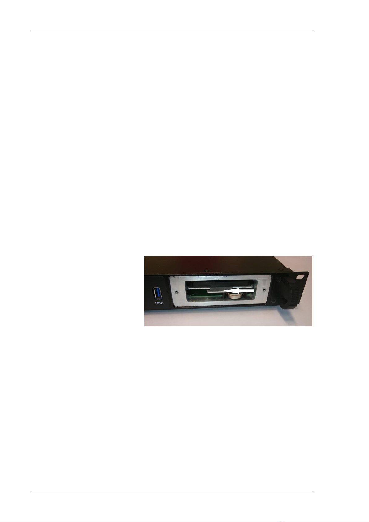
5.1 Internal Battery Replacement
The system uses a standard lithium battery for the real time clock. In the
event of loss of battery power, the unit will remain functional with the
exception of the real time clock. This will result in the wrong date and time
stamp on each file created or modified.
Battery replacement is recommended after five years.
No tools are required to change the battery. The battery is accessible by
removing the hard disk cover plate.
Battery type: Renata CR2477N
Replace only with a battery of this type and from this manufacturer.
SCOTTY ProMin HD real time clock battery
SCOTTY ProMin HD Equipment Manual
14 All rights reserved.
5.2 Fan Dust Filter Replacement
The system employs internal fans for air circulation. By removing the fan
cover the air inlet dust filter can be changed even during operation. No tools
are required.
Life cycle time of the filter pad may vary depending on the operating
environment. A replacement of the fan filter pad not later than 24 month is
recommended.
A proper filter pad can be ordered at SCOTTY:
Filter pad: P200 10mm, 36x130mm, part number: SD208306A1
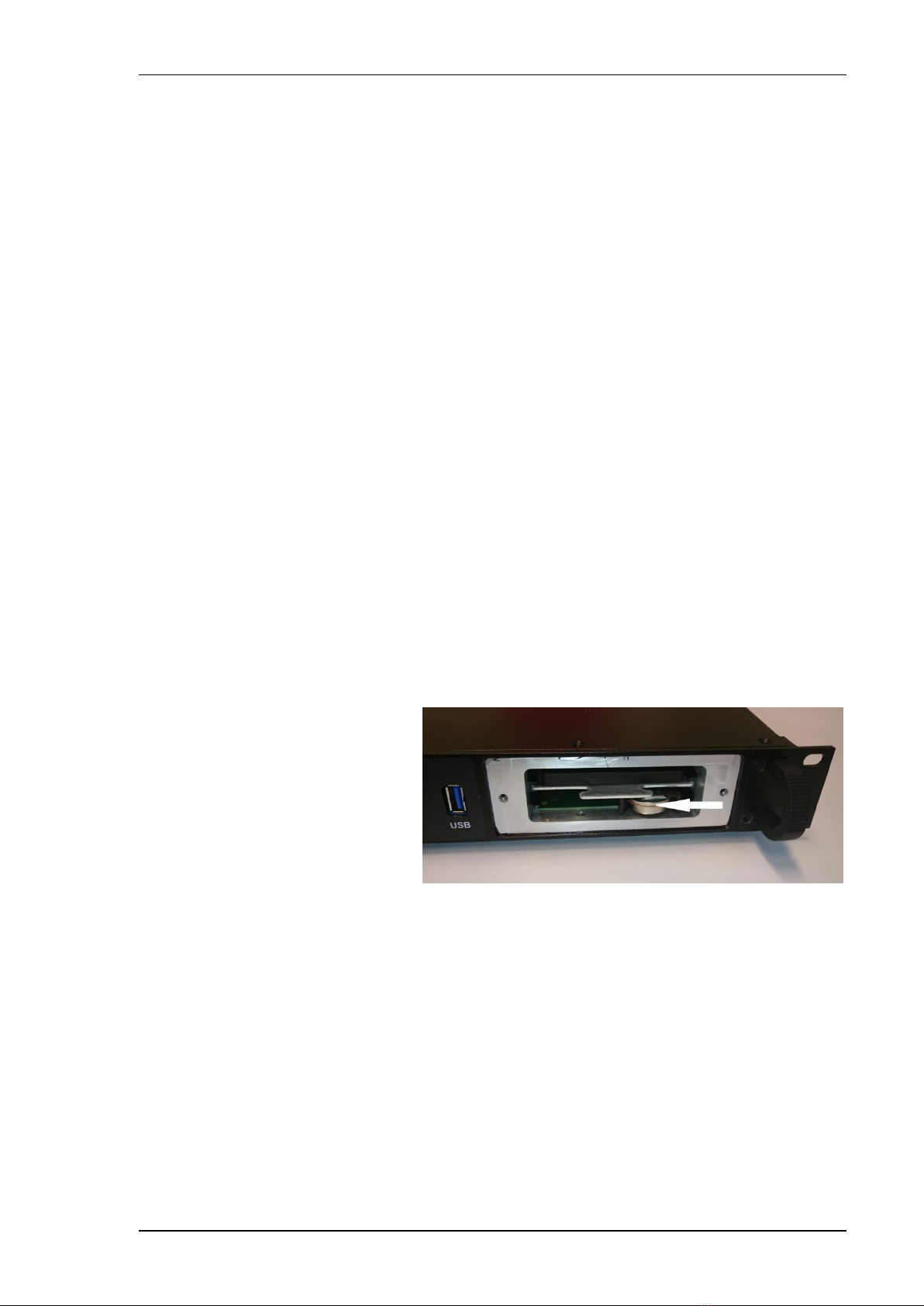
5.3 Storage Disk Replacement
A solid state disk is used for the operating system, the applications and user
data. No maintenance is required, but if necessary the disk can be removed by
pulling out the disk holder. Only use SCOTTY approved disks as replacement.
SCOTTY ProMin disk holder

SCOTTY ProMin HD Equipment Manual
All rights reserved. 15
6Physical Specifications
The SCOTTY ProMin HD is a 19” Rack Unit with the height of 1RU.
The unit is available as “long” and “short” order specified variant. The standard
configuration is “short” for AC units and “long” for DC units. Except for depth (and slightly
weight) long and short units are identical.
6.1 Weight and Dimensions - short variant
Width:
483 mm
445.5mm
19”
17.54”
(including flanges)
(excluding flanges)
Depth:
380 mm
14.96”
Height:
44 mm
1.73”
Weight:
4.4 kg
9.7 lbs
(slightly depending on power variant)
6.2 Weight and Dimensions - long variant
Width:
483 mm
445.5mm
19”
17.54”
(including flanges)
(excluding flanges)
Depth:
490 mm
19.29”
Height:
44 mm
1.73”
Weight:
4.7 kg
10.4 lbs
(slightly depending on power variant)

SCOTTY ProMin HD Equipment Manual
16 All rights reserved.
6.3 Outline Drawings
In the following drawings, dimensions are in mm; drawings not to scale.
Outline drawings, short variant

SCOTTY ProMin HD Equipment Manual
All rights reserved. 17
Outline drawings, long variant

SCOTTY ProMin HD Equipment Manual
18 All rights reserved.
This page intentionally left blank.

SCOTTY ProMin HD Equipment Manual
All rights reserved. 19
7Electrical Interfaces
7.1 Overview
The SCOTTY Communication Platform provides a rich set of interfaces.
System overview block diagram
Codec
(Audio/Video
Subsystem)
Computer
System
(PC)
System
Controller
Power Supply
Video Input DVI/HDMI
Video Output DVI/HDMI
6 Audio Inputs
2 Display DVI/HDMI
Video Input SDI
2 LAN 10M/100M/1G
4 USB
…
Power Input
12V Power Output
Maintenance RS232
2 RS232 + 1 RS422
…
6 Audio Outputs
2 Video Output Analog SD
…
Video Output Analog HD
…
Power Button Input
Power LED Output
…
Video Input VGA
3 Video Inputs Analog
…
USB 3.0 (Front)
RS232

SCOTTY ProMin HD Equipment Manual
20 All rights reserved.
7.2 Hardware Specification
The Computer subsystem is based on standard Intel-compatible CPUs.
CPU: Intel® Core™ i7-4650U 2x1.7GHz
RAM: 4 GB
HDD: mSATA-Flash Disk, 250GB
The Codec subsystem is based on a video processing DSP with hardware
accelerated encoding and decoding features.
7.3 Video Interfaces
Several video inputs to the Codec are available:
One SDI input, compatible with HD-SDI (3Gbit/s SMPTE 292M) and
SD-SDI (SMPTE 259M).
One DVI/HDMI-Input.
One VGA Input.
Three composite video inputs, also configurable as one S-video and
one composite input.
The DVI/HDMI outputs of the computer system are the main display outputs,
allowing single monitor operation or dual monitor with duplicated or
extended display operation, showing the PC desktop, the Teleport software
and the video overlay:
Two DVI/HDMI PC display outputs
Additional video outputs from the Codec are available, allowing multi-monitor
operation:
A DVI/HDMI video output
A HD analog video output, either VGA or component (YPbPr).
Two analog SD video outputs, configurable as two composite or one S-
Video output.
For a specification of the formats supported, please refer to the Software
Manual.
This manual suits for next models
2
Table of contents
Other Scotty Conference System manuals


